This is a repository copy of On analyzing the intra-frame power saving potentials of the IEEE 802.16e downlink vertical mapping.
White Rose Research Online URL for this paper: http://eprints.whiterose.ac.uk/116439/
Version: Accepted Version
Article:
Lagkas, T.D. orcid.org/0000-0002-0749-9794, Sarigiannidis, P. and Louta, M. (2013) On analyzing the intra-frame power saving potentials of the IEEE 802.16e downlink vertical mapping. Computer Networks, 57 (7). pp. 1656-1673. ISSN 1389-1286
https://doi.org/10.1016/j.comnet.2013.02.015
[email protected] https://eprints.whiterose.ac.uk/ Reuse
This article is distributed under the terms of the Creative Commons Attribution-NonCommercial-NoDerivs (CC BY-NC-ND) licence. This licence only allows you to download this work and share it with others as long as you credit the authors, but you can’t change the article in any way or use it commercially. More
information and the full terms of the licence here: https://creativecommons.org/licenses/ Takedown
If you consider content in White Rose Research Online to be in breach of UK law, please notify us by
On Analyzing the Intra-Frame Power Saving
Potentials of the IEEE 802.16e Downlink
Vertical Mapping
T. D. Lagkas* , Member, IEEE, P. Sarigiannidis*, Member, IEEE, and M. Louta*, Member,
IEEE *
Department of Informatics and Telecommunications Engineering, University of Western Macedonia, Kozani, Greece.
E-mail:{tlagkas,psarigiannidis,louta}@uowm.gr
Abstract
Worldwide Interoperability for Microwave Access (WiMAX) is generally considered as a competitive candidate networking technology for the realization of the 4G vision. Among the
key factors towards its successful and widespread deployment are the effective support of mobility and the provision of mechanisms for enabling service access at a high quality level in an efficient and cost-effective manner. Nonetheless, this effort should take into account and
adequately address strict and severe energy limitations that the mobile devices are currently facing. Power saving constitutes an issue of vital importance, as mobile terminals continue to
incorporate more and more functionalities and energy-hungry features in order to support the ever increasing user requirements and demands. The standard employs variations of power saving classes in a frame-to-frame basis, while recent power saving mechanisms proposed in
related research literature limit their activity in whole frames, neglecting, thus, the intra-frame power saving capabilities. In this work, the intra-frame energy conservation potentials of the
mobile WiMAX network are studied and a novel analytical approach is provided, focusing on the downlink direction where the bandwidth allocation involves idle intervals and dynamic inactivity periods. Specifically, we endeavour to accurately analyse the potential energy
findings are thoroughly cross-validated via simulation, providing clear insights into the intra-frame energy reduction capabilities.
Keywords
IEEE 802.16, downlink mapping, intra-frame power saving, sleep slots, WiMAX
1. Introduction
Worldwide Interoperability for Microwave Access (WiMAX) is a competitive candidate networking technology that efficiently supports emerging services and advanced service features and capabilities. With IEEE 802.16e providing the asset of mobility and IEEE 802.16m (also
known as mobile WiMAX) currently under standardization, WiMAX advances to a fully mobile and efficient wireless communication standard, constituting, thus, a valuable candidate player in
the 4G era.
The standard tends to support a wide variety of mobile devices, including mobile phones with multimedia enhancements, PDAs, laptops, etc. Mobile devices incorporate an increasing
number of processing units and functionalities in order to support the ever growing user needs and demands; however, this fact negatively affects the battery lifetime. This phenomenon is
intensified by latest achievements concerning the transmission rate increase and the coverage range extension, which both bring substantial side effects. In the light of the aforementioned and taking into account limitations and deficiencies in energy supply, efficient power management is
an issue of outmost importance and has, thus, gained the attention of the researchers.
The standard addresses the power consumption issue, specifying a power saving mode at
Medium Access Control (MAC) layer. In order to maintain an efficient power consumption level, IEEE 802.16e standard specifies sleep mode and idle mode-based operations. Mobile devices can operate in these modes in case no activity is monitored and can return to the normal
operation mode whenever needed. Focusing on power saving mechanisms exploiting sleep mode of operation, the basic principle underlying [1, 2] is to apply predefined intervals, referred to as
the air interface with the Base Station (BS), reducing, thus, its power consumption. During sleep window periods, the MS enters the sleep state and it is considered unavailable, unable to either send or receive traffic. Each sleep window is followed by a listen window, during which the MS
returns to normal state. Thus, between sleep states, the MS is able to recover in order to exchange control messages with the BS.
Three variations of power-saving classes have been designed to meet energy management requirements of the various types of applications and services [3]. In the first power-saving class, each listen window of fixed length is followed by a sleep window whose length is twice the
length of the previous sleep window, without however exceeding a final sleep window size. Before entering the first power-saving class, the BS indicates to the MS the initial sleep window
size and the final sleep window size. Once the final sleep window size is reached, all the subsequent sleep windows are of the same length [3]. The sleep windows of power-saving class two have a fixed length and are followed by a listen window of fixed length. Again, the BS
indicates to the MS the sleep and listen window sizes. Lastly, the third power-saving class operation, on the contrary to the other classes, involves a single sleep window. In a similar
manner to the first and second power saving class, the BS informs the MSs about the start time and the length of the sleep window. At the end of the sleep window, the power-saving operation becomes inactive [3]. Numerous studies have followed, studying power management issues
based on these three classes. All these efforts operate in a frame-to-frame basis, where each MS negotiates its state mode with the BS concerning the whole frame. Nevertheless, they disregard
the intra-frame power management capabilities, ignoring the possibility for an MS to enter a sleep state within the duration of the frame, reducing even more its battery consumption.
In this work, we endeavor to cover this absence, by thoroughly studying power management
in an intra-frame basis. Specifically, we propose an energy conservative extension to a well-known mapping algorithm, supported by a comprehensive analysis of the potential power
analytical framework, where the potential intra-frame sleep time intervals are identified and presented under various scenarios considering multiple MSs and different traffic demands. It needs to be stressed out that hardware switching between reception and sleep mode may cause
extra energy consumption, which could limit the power saving capabilities of the examined scheme. However, the typical power consumption values presented in the WiMAX chipset
specifications [4] and adopted in [5-8] (power in receive mode: 280mW, power in idle mode: 120mW, power in sleep mode: 10mW, additional power when switching between receive and sleep modes: 1mW) reveal that the maximum of two switches which may occur during one
frame period according to the analyzed mechanism do not add to the energy consumption very much, and therefore intra-frame power saving is advantageous.
The remainder of this paper is organized as follows. The OFDMA technique and the bandwidth allocation fundamentals are described in Section 2. In Section 3, the intra-frame power saving capabilities are identified and the related efforts in research literature are revisited.
Section 4 identifies energy conservation potentials in downlink vertical mapping and analytically models the proposed energy conservative technique. Section 5 validates our analysis via
simulation and provides extensive performance results in terms of potential sleep time. A comparative analysis of intra-frame and inter-frame power saving is conducted in Section 6. Finally, Section 7 concludes this paper and highlights our future plans.
2. OFDMA Technique and Intra-frame Bandwidth Allocation Fundamentals
IEEE 802.16 WiMAX system incorporates four alternate physical specifications operating in
different frequencies. These include the WirelessMAN-SC, the WirelessMAN-SCa, the WirelessMAN-OFDM, and the WirelessMAN-OFDMA. In addition, there is another physical layer, WirelessHUMAN PHY, which is specified for the license-exempt bands [9]. In particular,
WirelessMAN-OFDM PHY and WirelessMAN-OFDMA PHY are designed for operation below the 11-GHz licensed band, based on the Orthogonal Frequency Division Multiplexing (OFDM)
respectively. Mobile WiMAX adopts WirelessMAN-OFDMA PHY only, constituting OFDMA the dominant multiple access technique of the modern IEEE 802.16 standards.
OFDMA divides the available frequency spectrum into a large number of subcarriers and
transmits the input data by mapping it into the subcarriers. In essence, OFDMA is the key feature that ties the physical (PHY) with the MAC layer. It is responsible for realizing multiple
subscriber access by flexibly sharing the time and frequency domains. The BS governs the communication process amongst the MSs, which involves repetitive broadcasting of communication frames. Each frame has predefined fixed time duration, while full duplex
communication is realized by sub-diving each frame’s width into two sub-frames: the downlink sub-frame, during which the BS broadcasts the data destined to the various connected MSs, and
the uplink sub-frame, which is responsible for organizing the data transferred from the MSs to the BS. OFDMA defines two different techniques for carrying traffic at the downlink and uplink directions. The Frequency Division Duplexing (FDD) technique, according to which traffic of
both directions is transmitted in parallel in different frequencies and, on the other hand, the Time Division Duplexing (TDD) technique that involves consecutive transmissions of the traffic of the
two directions in time in the same frequency, with the uplink sub-frame following the downlink sub-frame. Due to TDD’s flexibility that allows for dynamic adjustment of the width ratio between the two directions, it is the most popular one and it is adopted in the context of this
study.
In order to facilitate the bandwidth assignment process in both downlink and uplink
sub-frames, OFDMA defines slot as the minimum allocation physical resource. To be more specific, bandwidth distribution is synonymous to slot allocation within the allocation bin, where the dimensions are time and frequency. An intra-frame allocation process takes place just before the
beginning of the frame, where the available slots are granted to the subscribers to send (i.e., uplink sub-frame) and/or receive (i.e., downlink sub-frame) data. The process of allocating slots
mapping. In essence, the mapper is directly connected with the scheduler; having acquired and processed traffic requests, concludes to a final transmission program with respect to both downlink and uplink directions. At this point, it should be mentioned that downlink requests
should conform to a shaping rule, with each request forming a rectangular inside the OFDMA allocation bin, having one dimension associated with the time and the other associated with the
frequency domain. An indicative mobile WiMAX frame based on TDD technique is illustrated in Fig. 1.
Fig. 1. A TDD Mobile WiMAX frame instance
Each frame begins with a preamble, a short control period used for synchronization and
channel estimation. The downlink sub-frame includes two critical control messages, the downlink map (DL-MAP) and the uplink map (UL-MAP), which define the time duration of each burst, the modulation, and the forward error control (FEC) coding scheme for each MS. The
frame control header (FCH) field proceeds DL-MAP and UL-MAP, as it provides frame configuration information, such as the MAPs’ length and their corresponding PHY properties
interferences as the BS passes from transmit to receive mode and vice versa.
3. Intra-frame Power Capabilities and Related Efforts
Considering that time duration of each frame is fixed and predefined in conjunction with the
fact that a single or multiple MSs may experience short or large periods of idleness within the duration of a single frame, it may be easily concluded that an MS may utilize only a portion of
the available allocation space. Specifically, each MS may be associated with one of the following states: a) begins its transmission or reception at the beginning of the frame and completes them at the end of the frame, b) begins its transmission or reception at the beginning
of the frame and completes them before the end of the frame, c) begins its transmission or reception after the beginning of the frame and completes them at the end of the frame, d) begins
its transmission or reception after the beginning of the frame and completes them before the end of the frame, and e) does not participate either in the transmission phase or the reception phase or both. Except for the first state, all other states may incorporate sleep periods, which may be
exploited in order to reduce power consumption, without, however, overshadowing the network performance during the transmission and/or the reception phase. We refer to the sleep slots
incorporated in states (b), (c), and (d) as intra-frame sleep slots.
Due to the OFDMA nature, the power consumption properties should be investigated along with the mapping process, since the mapping procedure significantly affects the allocation
strategy within the OFDMA allocation space. Subsequently, in accordance with the specified strategy and the resulting slot assignment in the allocation bin, MSs inactivity periods and
idleness behavior may be defined. Even though noticeable research efforts have been performed in order to provide power management frameworks (indicatively see [10-12]), to the best of our knowledge no prior published work on intra-frame power consumption exists. In the current
study, we aim to fill this gap by analytically examining the power saving capabilities in the vertical (mapping) perspective, since it imposes a very challenging sight. A number of
the context of this work, Simple Packing Algorithm (SPA) [16], the simplest dynamic mapping algorithm, is adopted in order to explore and provide clear insights on the intra-frame power reduction capabilities.
Our approach contributes towards an accurate analytical approach, which is thoroughly verified by comparison against simulation outcome. A number of related research studies present
analytical models of WiMAX systems. In [17, 18] the authors develop a generic analytical model of WiMAX systems that takes into account frame structure, precise slot sharing-based scheduling and channel quality variation of WiMAX systems and provides closed-form
expressions for Erlang-like performance parameters such as throughput per user or channel utilization. Although this work presents a notable analytical approach, it neglects the power
consumption issue.
In a nutshell, the contribution of this paper is two-folded. First, the intra-frame energy conservation potentials of the IEEE 802.16e downlink sub-frame are explored, adopting the
vertical SPA algorithm. Second, an accurate analytical approach is provided, which is thoroughly verified against simulation outcomes considering different scenarios and realistic test-cases.
4. Analysis of the Vertical SPA Power Saving Capabilities
4.1.Energy Conservation in Vertical SPA
Vertical SPA is a fast and easy to implement mapping technique for assigning OFDMA slots
provided by the rectangular structured 802.16 sub-frame for downlink transmissions to user bandwidth requests [16]. Because of its low requirements in processing resources, it can be
efficiently programmed along with the scheduler into the hardware of any WiMAX BS. The term “vertical” indicates that slots are allocated to MSs by filling consecutive columns of the downlink sub-frame. Specifically, each request that the scheduler provides for mapping is
assigned with slots along a column, which corresponds to a pair of symbols. In case the slots for an MS exceed the column height, that is the number of available sub-channels, the allocation
802.16 physical layer specifications for the downlink direction, which define the data region as a rectangular shaped area of slots in the sub-frame that is allocated to an MS for reception. On this basis, the vertical SPA scheme never maps requests to a non-integer number of multiple
columns. Hence, each served MS is eventually allocated either a fraction of a single column or multiple whole columns. The objective is to keep the mapping area in a rectangular shape in any
case. Thus, the respective algorithm maps each request at the frequency dimension first and then at the time dimension. Each time a new request is processed for mapping, it is examined whether there is enough space in the current column to allocate the required slots; otherwise, the next
column is used. The procedure completes for a single frame when all requests are mapped or there are no available slots in the downlink sub-frame to allow the formation of additional
rectangular data regions according to the bandwidth requirements posed. The algorithmic description of the vertical SPA operation is as follows:
- The number of MSs in the network with non-zero requests is set to N
- The set of MS requests S = {Ri | i ∈∈∈∈ [1, N]}, measured in number of slots, is initiated
- The downlink sub-frame height (i.e., the available number of sub-channels) is set to H - The downlink sub-frame width (i.e., the available number of slots in the time domain) is set
to W
- The number of residual slots in the time domain Res_W is set equal to W (i.e., Res_W = W initiation)
- The number of residual subchannels Res_H is set equal to H (i.e., Res_H = H initiation)
- For each Ri∈∈∈∈ S
- if Ri≤ Res_H
- Res_H = Res_H - Ri
- else if Ri≤ Res_W×H
- Res_W = Res_W - R Hi
- Res_H = H
- S = S – {Ri}
- End when S = ∅ or (Ri > Res_H and Ri≤ Res_W×H, ∀Ri∈ S)
The vertical SPA scheme as described above involves inactivity periods for the MSs assigned with allocation space in the downlink sub-frame. This feature can be exploited to enable
intra-frame power saving. In more detail, each MS is actually active (Rx mode) only during the OFDMA symbols allocated to it, tuned at the sub-channels corresponding to its slots. Hence, it
could be set to a low power mode for the residual downlink sub-frame (i.e., before and after its reception period). It is noted that an MS transceiver in sleep mode can conserve up to eleven twelfths of the energy consumed when being in the idle state [4-8]. When in sleep mode, data
transmission or reception for an MS is not allowed. However, as an MS is not involved in such activities outside the region formed by its allocated slots in the downlink sub-frame, the adoption
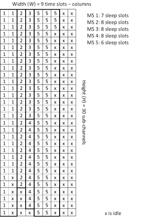
and the transition to intra-frame sleep state when applying vertical SPA does not negatively impact and/or degrade network performance in any manner. Fig. 2 presents an illustrative example of the mapping process using the vertical SPA technique. In this case, the requests of
five MSs are mapped to the slots provided for downlink traffic considering a 5ms long frame, assuming a downlink-to-uplink ratio equal to 1:1. The data regions, which always form
Fig. 2. Example of the downlink sub-frame resource space, when mapping 5 MS requests via vertical SPA, considering 5ms long frame and 1:1 DL-to-UL ratio
4.2.Mathematical Approach
The power saving capabilities of the vertical SPA mapping scheme are mathematically
analyzed in this subsection. Each frame constitutes a distinguished mapping cycle, where the bandwidth requests provided as output from the scheduler are examined in a sequential way for
slot allocation. It is considered that the requests for downlink resources originate from a number of MSs that form the concerned WiMAX network. As it is typically assumed in such analytical procedures, the number of slots requested by each MS is an independent identically distributed
variable following a Poisson distribution with expected number of occurrences equal to λ. Actually, in this case, an MS could never request for zero downlink slots, thus, the above
slots follows in fact a variant form of the Poisson distribution, according to which there is null probability to be equal to zero. Therefore, the respective formulae are properly normalized throughout this analysis. However, it should be noticed that an MS participating in the network
may occasionally omit downlink slots requests in specific frames. The following analysis eventually takes into account this special case and considers also as intra-frame sleep intervals
the downlink sub-frame periods during which an MS remains totally inactive. On these grounds, each time the rest of this analysis refers to an MS request, a bandwidth request for more than zero downlink slots is assumed. In the light of the aforementioned, it may be concluded that
since null requests are possible but not really mapped, the mean number of requested slots per MS which are actually mapped in the downlink sub-frame bin space does not exactly equal λ.
Initially, we examine the intra-frame power saving potentials of a single MS, which receives downlink slots applying the vertical SPA. The MS is able to transit to sleep mode for the duration of the slots preceding those it occupies or for those following in the same sub-frame or
even for the whole duration of the downlink sub-frame in case it has not requested for any slots. We call these slots sleep slots and their number depends on the width of the data region allocated
to the MS and the width of the downlink sub-frame. The probability p that a request occupies k columns is equal to the probability of involving more than (k – 1)×H slots and less or equal to
k×H slots, as it is expressed by the following equation:
( 1) 1
1
!
[ ] , 0, , , ,
!
i k H
i k H i
i
e i
p k k W k W H
e i λ λ λ λ λ × − = − × + + ∞ − =
=
∑
> 1 ≤ ≤ ∈∑
Z (1)
The mean number of columns that form the data region allocated to a requesting MS is given by
the weighted average:
1
[ ] ,
W
k
M p k k W +
=
=
∑
× ∈Z (2), ,
s=W −M M ≤W ∈W Z + (3)
The next step in this analysis is to estimate the mean number of MS requests that are mapped in a downlink sub-frame in order to determine the aggregate number of sleep slots present.
Assuming first that no more than one request is mapped per column, the mean number of MSs that are served in a downlink sub-frame is resulted by:
, ,
W
R M W W
M
+
= ≤ ∈Z (4)
We then calculate the mean number of requests that are mapped to columns already occupied by
another station. The basis of this calculation is the fact that the probability Q[l] that l consecutive
requests are allocated slots in a single column of height H is derived by the probability they
occupy m slots (l ≤ m ≤ H), while the following request occupies more than H-m slots. In this
aspect, it is found that:
1 0
[ ] [ ] [ ], , ,
H l
l i
Q l P H i P i l H l H
−
+
=
=
∑
− × > 1 ≤ ≤ ∈Z (5)It is clarified that Py[x] is the probability that the aggregate number of slots requested by y MSs
equals x, whereas Py[>x] is the probability that the number of requested slots is higher than x.
Concerning the calculation of Py[x], it is not accurate to refer to the additive property of the
Poisson distribution, which states that the sum of Poisson variables also follows the Poisson
distribution, since in our case the added random variables are not exactly Poisson distributed, as
it was explained earlier. Considering that the probability y MSs request for x aggregate slots
results from the probability that y-1 MSs request x-i aggregate slots, while the next MS requests i
slots, we end up with the following recursive formula:
( 1)
1 1
1
[ ] [ ] [ ], , ,
x y
y y
i
P x P x i P i x y x y
− −
+ −
=
=
∑
− × ≥ ∈Z (6)Note that Py[x] = 0, when x < y, because a MS can never request for zero downlink slots. The
1
1
!
[ ] , 0,
! x i i e x
P x x
e i λ λ λ λ λ − + ∞ − =
= > ∈
∑
Z (7)In regards to equation (5), Py[>x] can be computed in a straightforward manner as shown below:
1
[ ] [ ] 1 [ ], , ,
x
y y y
i x i y
P x P i P i x y x y
∞
+
= + =
> =
∑
= −∑
≥ ∈Z (8)By deconstructing the recursive formula provided in equation (6), the following iterative formula
can be derived:
(
)
1 2 1
( 1) ( 2) 1
1 1 1 1 1 2 1 1
1 1 1
[ ] [ ] [ ] [ ] [ ] , ,
y y
x y x y x
y y y
i i i
P x P x i P i P i P i x y x y
− − − − − − − + − − = = = = − × × × × ≥ ∈
∑
∑
L∑
L Z (9)Eventually, the mean number of requests that can be mapped to a column of height H already
occupied by another MS equals:
2
[ ] ( 1),
H
i
A Q i i H +
=
=
∑
× − ∈Z (10)Considering the whole downlink sub-frame and taking into account that columns which are part
of data regions of width greater than one slot are not able to include more than one MS request,
the mean number of requests that can be mapped to columns already occupied by other MSs is
given by:
( 4)
,
W
E A E A R W
M
+
= × → = × ∈Z (11)
It is now possible to proceed to the estimation of the mean number of sleep slots available to all
MSs that can be served during a downlink sub-frame (denoted by SS), assuming that they
generate non-zero requests. Taking into account that an average number of s sleep slots
corresponds to each one of the R MSs and that each one of the E MSs may employ W – 1 sleep
slots, we conclude that:
( 1),
SS= × + ×R s E W− ∈W Z+ (12)
considering that the available space is filled with requests and no empty columns are left in the resources bin due to limited number of requests. In a more realistic case, where there is a finite number of MSs requesting for downlink bandwidth, the analysis is adapted accordingly. To be
more specific, if the number of MS requests is higher than R + E, then the formula of equation (12) holds as is. In case the number of MS requests is lower than R + E, for Nr MSs generating
downlink bandwidth requests, the R/(R + E) portion of them can use on average s sleep slots each, whereas the rest (i.e. E/(R + E)) have at their disposal W – 1 sleep slots, as it is shown below:
(
)
(
)
( 1)
, 1
r
r r
r
R s E W N R E
SS N W
R s E W N R E
R E
+
× + × − ≥ +
= ∈
× × + × − < +
+ Z (13)
SSr represents the average number of sleep slots that are associated with MSs which are
actually served, that is they are assigned downlink slots in the examined sub-frame. This case
clearly demonstrates the presented intra-frame power saving concept, where stations
participating in a sub-frame are at the same time capable of conserving energy. For reasons of
analysis completeness, we further estimate the sleep slots of the MSs which do not request any
downlink slots during the frame. It should be noted that this is not a typical case of intra-frame
power saving, since the particular stations do not participate in the examined sub-frame and just
transit to sleep mode for its whole duration. We initially define the probability that an MS
generates no resource request as:
0
, 0
0!
e−λλ e−λ λ
= = >
P (14)
Assuming that the total number of MSs in the network is NT, the estimated number of MSs that
do not generate bandwidth requests is equal to:
,
z T T
N = ×P N N ∈Z + (15)
Thus, the number of sleep slots associated with MSs that request no downlink slots is given by:
Similarly, the number of MSs that request for downlink slots is estimated to be:
(
1)
r T T
N = −P N , N ∈Z + (17)
In order to conclude our analysis, we calculate the number of sleep slots which are related with MSs that are not served in the examined sub-frame, because not enough available
downlink slots are left to allocate to their bandwidth requests. The number of these unserved MSs is equal to:
(
)
0
r r
u
r
N R E N R E
N
N R E
− + ≥ +
= < +
(18)
Consequently and given the fact that any MS which is not active during the sub-frame transits to sleep mode for the whole period, the total number of sleep slots per downlink sub-frame
associated with unserved MSs is given by:
,
u u
SS = N ×W ∈W Z + (19)
It is noted again that similarly to the case of the non-requesting MSs, the sleep mode transition
during the whole sub-frame because of the lack of available resource space is not considered as a
typical intra-frame power saving case.
5. Numerical Results
The analytical solution described in the previous section is cross-validated by means of a
simulation program developed in MATLAB1. The specific program models the downlink mapping procedure allocating WiMAX OFDMA slots to MSs bandwidth requests, according to
the vertical SPA technique. The input of the simulator is considered to be the output of the
packet scheduler, which generates requests according to the typical Poisson process. The
simulation output is the number of sleep slots for all participating MSs (served, non-requesting,
and unserved, corresponding to SSr, SSz, and SSu, respectively), averaged considering 10,000
runs, which correspond to different mapping cycles, until the relative statistical error is lower
than 2%.
1
The adopted frequency diversity mode is PUCH (Partially Used sub-Channelization), which constitutes the most common approach. According to PUCH, the frame includes 30 sub-channels, which correspond to the downlink sub-frame’s height represented by H rows. The
downlink sub-frame width (denoted by W) depends on the downlink-to-uplink sub-frame ratio, which may vary among 1:1, 2:1, and 3:1, and the frame duration, which may range from 2ms to
20ms. This paper considers the default frame duration of 5ms as well as the 10ms, and 20ms values. Regarding the exact frame structure, the OFDMA slots available for request mapping correspond to the resource space that remains after the deduction of the Preamble, MAP, and
FCH downlink fields. More specifically, in a 5ms long frame, W equals to 9, 12, and 15 slots for downlink-to-uplink sub-frame ratios of 1:1, 2:1, and 3:1, respectively. Considering frame
duration of 10ms, the downlink sub-frame width is 21, 27, and 33 slots for downlink-to-uplink sub-frame ratios of 1:1, 2:1, and 3:1, respectively. Lastly, for the 20ms long frame, the downlink sub-frame width is 45, 60, and 70 slots for downlink-to-uplink sub-frame ratios of 1:1, 2:1, and
3:1, respectively. Table I summarizes the presented frame structure parameters adopted in this work.
TABLE I.PROPERTIES OF THE ADOPTED 802.16 FRAME.
OFDMA PHY Mode PUSC (H = 30 sub-channels)
Frame Duration 5ms (default) 10ms 20ms
DL-to-UL Ratio 1:1 2:1 3:1 1:1 2:1 3:1 1:1 2:1 3:1
Number of Slots in
the Time Domain (W) 9 12 15 21 27 33 45 60 70
The following figures graphically depict the results provided by the analytical model along
with the simulation results, considering four different scenarios. As a first note, a very satisfactory match between the analytical and the simulation results may be observed in all cases,
mathematic analytical models of the SPA or any other request mapping technique, due to the absence of such research attempts in the known related literature.
Initially, the effect of the mean request size (corresponding to the Poisson parameter λ) on
the number of sleep slots is explored in a 5ms frame, for a fixed number of 30 MSs that participate in the network and may generate downlink requests without any restrictions. Fig. 3
illustrates the number of sleep slots that are associated with served MSs, which are stations that are actually allocated downlink slots in the sub-frame. As already explained, this is the type of sleep slots that is fully representative of the examined intra-frame power saving scheme, since
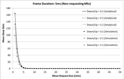
these slots are related with MSs which participate in the downlink sub-frame with data receiving activity. In Fig. 4, the mean number of sleep slots, that are associated with MSs which do not
request for downlink slots, are plotted against the mean request size. These non-requesting MSs exhibit no downlink activity and transit to sleep mode for the whole downlink sub-frame duration, which case is not representative of the intra-frame power saving mechanism, as already
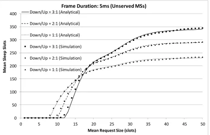
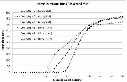
explained. Moreover, the number of sleep slots related to MSs that request for downlink slots, but do not get served, due to unavailability of resources, is graphically depicted in Fig. 5 as a
function of the mean request size. The case of unserved MSs is also not fully considered as intra-frame power saving, since the specific stations are not active at all during the downlink sub-frame. As it can be seen in Fig. 3, for higher Downlink/Uplink ratios, the mean number of the
available sleep slots per frame is higher, since there is a larger resource space in the downlink sub-frame. Initially, for small requests, the number of intra-frame sleep slots is low, since there
are multiple non-requesting MSs, as it is depicted in Fig. 4. Then, it is evident in Fig. 3 that for a specific range of request sizes the number of sleep slots is almost constant to a maximum value. This is attributed to the fact that almost all 30 MSs are requesting and are allocated slots. They
are all associated with sleep slots and almost none of them is unserved, as it can be seen for the particular range of request sizes in Fig. 5. From that point on, as the request sizes increase, the
from Fig. 5. This phenomenon leads to intra-frame sleep slots decrement, which is evident in Fig. 3. 0 50 100 150 200 250 300 350 400 450
0 5 10 15 20 25 30 35 40 45 50
M e a n S le e p S lo ts
Mean Request Size (slots) Frame Duration: 5ms (Served MSs)
Down/Up = 3:1 (Analytical)
Down/Up = 2:1 (Analytical)
Down/Up = 1:1 (Analytical)
Down/Up = 3:1 (Simulation)
Down/Up = 2:1 (Simulation)
[image:20.595.86.511.440.714.2]Down/Up = 1:1 (Simulation)
Fig. 3. Mean number of sleep slots of served MSs per DL sub-frame versus the mean request size, considering frame duration of 5ms and a total of 30 MSs
0 20 40 60 80 100 120 140 160 180
0 5 10 15 20 25 30 35 40 45 50
M e a n S le e p S lo ts
Mean Request Size (slots)
Frame Duration: 5ms (Non-requesting MSs)
Down/Up = 3:1 (Analytical)
Down/Up = 2:1 (Analytical)
Down/Up = 1:1 (Analytical)
Down/Up = 3:1 (Simulation)
Down/Up = 2:1 (Simulation)
Down/Up = 1:1 (Simulation)
Fig. 4. Mean number of sleep slots of non-requesting MSs per DL sub-frame versus the mean
0 50 100 150 200 250 300 350 400
0 5 10 15 20 25 30 35 40 45 50
M
e
a
n
S
le
e
p
S
lo
ts
Mean Request Size (slots) Frame Duration: 5ms (Unserved MSs) Down/Up = 3:1 (Analytical)
Down/Up = 2:1 (Analytical)
Down/Up = 1:1 (Analytical)
Down/Up = 3:1 (Simulation)
Down/Up = 2:1 (Simulation)
[image:21.595.88.512.75.349.2]Down/Up = 1:1 (Simulation)
Fig. 5. Mean number of sleep slots of unserved MSs per DL sub-frame versus the mean request size, considering frame duration of 5ms and a total of 30 MSs
Next, we present the corresponding results for different frame durations, in an effort to
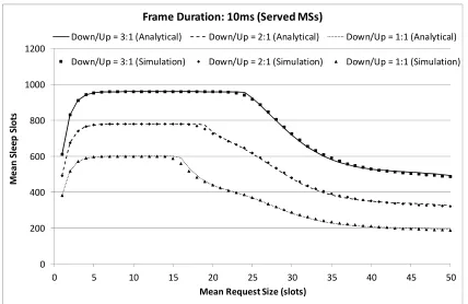
examine the effect of the frame size on the number of intra-frame sleep slots. In Figs. 6, 7, and 8, we provide the related graphs regarding the mean number of sleep slots associated with served, non-requesting, and unserved MSs, respectively, for 10ms long frame and a fixed number of 30
MSs. It is apparent from Fig. 6 that the particular frame length allows for more intra-frame sleep slots than the 5ms frame. The reason is the increased resource space, which includes more
downlink slots for request mapping. Furthermore, the 10ms long frame retains maximum sleep slots for a larger range of request sizes, as it can be seen in Fig. 6. This is attributed by the fact that the larger resource space can sustain larger requests till some MSs are not served, as shown
in Fig. 8. Of course, when the number of unserved MSs further increases, the sleep slots associated with these stations also increase, but the actual intra-frame sleep slots represented in
0 200 400 600 800 1000 1200
0 5 10 15 20 25 30 35 40 45 50
M e a n S le e p S lo ts
Mean Request Size (slots) Frame Duration: 10ms (Served MSs)
Down/Up = 3:1 (Analytical) Down/Up = 2:1 (Analytical) Down/Up = 1:1 (Analytical)
[image:22.595.85.513.72.350.2]Down/Up = 3:1 (Simulation) Down/Up = 2:1 (Simulation) Down/Up = 1:1 (Simulation)
Fig. 6. Mean number of sleep slots of served MSs per DL sub-frame versus the mean request size, considering frame duration of 10ms and a total of 30 MSs
0 50 100 150 200 250 300 350 400
0 5 10 15 20 25 30 35 40 45 50
M e a n S le e p S lo ts
Mean Request Size (slots)
Frame Duration: 10ms (Non-requesting MSs)
Down/Up = 3:1 (Analytical)
Down/Up = 2:1 (Analytical)
Down/Up = 1:1 (Analytical)
Down/Up = 3:1 (Simulation)
Down/Up = 2:1 (Simulation)
Down/Up = 1:1 (Simulation)
[image:22.595.88.513.394.668.2]0 50 100 150 200 250 300 350 400 450 500
0 5 10 15 20 25 30 35 40 45 50
M
e
a
n
S
le
e
p
S
lo
ts
Mean Request Size (slots) Frame Duration: 10ms (Unserved MSs)
Down/Up = 3:1 (Analytical)
Down/Up = 2:1 (Analytical)
Down/Up = 1:1 (Analytical)
Down/Up = 3:1 (Simulation)
Down/Up = 2:1 (Simulation)
[image:23.595.88.512.61.333.2]Down/Up = 1:1 (Simulation)
Fig. 8. Mean number of sleep slots of unserved MSs per DL sub-frame versus the mean request size, considering frame duration of 10ms and a total of 30 MSs
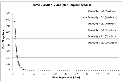
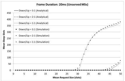
The third frame length studied is 20ms. The corresponding results on the mean number of
sleep slots versus the mean request size are depicted in Figs. 9, 10, and 11. As expected, Fig. 9 reveals that this frame size ensures the highest number of intra-frame sleep slots. In the same
figure, it is indicative that the 3:1 Downlink/Uplink ratio maintains maximum sleep slots even for mean request size of 50 slots. This means that the available downlink resource bin is so large that it takes greater than 50-slot request to lead to unserved MSs, as it can be seen in Fig. 11.
0 500 1000 1500 2000 2500
0 5 10 15 20 25 30 35 40 45 50
M e a n S le e p S lo ts
Mean Request Size (slots) Frame Duration: 20ms (Served MSs)
[image:24.595.87.512.76.345.2]Down/Up = 3:1 (Analytical) Down/Up = 2:1 (Analytical) Down/Up = 1:1 (Analytical) Down/Up = 3:1 (Simulation) Down/Up = 2:1 (Simulation) Down/Up = 1:1 (Simulation)
Fig. 9. Mean number of sleep slots of served MSs per DL sub-frame versus the mean request size, considering frame duration of 20ms and a total of 30 MSs
0 100 200 300 400 500 600 700 800 900
0 5 10 15 20 25 30 35 40 45 50
M e a n S le e p S lo ts
Mean Request Size (slots)
Frame Duration: 20ms (Non-requesting MSs)
Down/Up = 3:1 (Analytical)
Down/Up = 2:1 (Analytical)
Down/Up = 1:1 (Analytical)
Down/Up = 3:1 (Simulation)
Down/Up = 2:1 (Simulation)
Down/Up = 1:1 (Simulation)
[image:24.595.86.512.392.674.2]0 50 100 150 200 250 300 350 400 450
0 5 10 15 20 25 30 35 40 45 50
M
e
a
n
S
le
e
p
S
lo
ts
Mean Request Size (slots) Frame Duration: 20ms (Unserved MSs)
Down/Up = 3:1 (Analytical)
Down/Up = 2:1 (Analytical)
Down/Up = 1:1 (Analytical)
Down/Up = 3:1 (Simulation)
Down/Up = 2:1 (Simulation)
[image:25.595.84.513.58.338.2]Down/Up = 1:1 (Simulation)
Fig. 11. Mean number of sleep slots of unserved MSs per DL sub-frame versus the mean request size, considering frame duration of 20ms and a total of 30 MSs
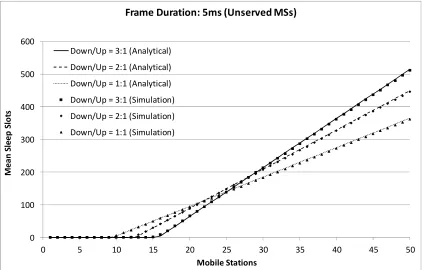
Next, we study the manner in which the number of MSs that form the network affects the
mean number of sleep slots per frame, assuming that the Poisson parameter λ which corresponds to the mean request size is set equal to 20 slots and is not modified in the context of this
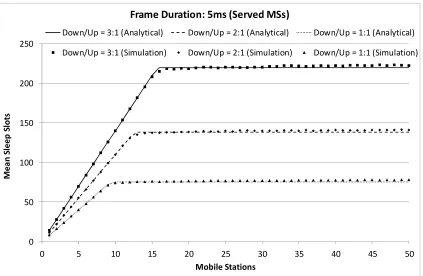
experiment. Considering the 5ms long frame, the specific results regarding the served and unserved MSs are plotted in Figs. 12 and 13, respectively. We clarify at this point that the graphs presenting the number of sleep slots associated with non-requesting MSs versus the total number
of participating MSs are deliberately omitted, because for λ=20 all stations produce non-zero bandwidth requests. Thus, there are not actually any non-requesting MSs to represent. As it may
be observed from the results depicted in Fig. 12, a linear relationship between the number of MSs and the mean number of intra-frame sleep slots exists up to a certain point with the number of sleep slots converging to a specific value. A higher downlink-to-uplink ratio results in a
higher increase rate and a higher sleep slots convergence number, because of the increased capability of the larger resource bin to serve more MSs, which are then related with more sleep
associated with a fixed number of sleep slots, which corresponds to the convergence values seen in Fig. 12. The increment of the unserved MSs as the number of participating stations increases is evident in Fig. 13. Actually, the point at which unserved MSs start to appear corresponds to
the maximum number of stations that can be served in the specific downlink sub-frame size.
0 50 100 150 200 250
0 5 10 15 20 25 30 35 40 45 50
M
e
a
n
S
le
e
p
S
lo
ts
Mobile Stations
Frame Duration: 5ms (Served MSs)
Down/Up = 3:1 (Analytical) Down/Up = 2:1 (Analytical) Down/Up = 1:1 (Analytical)
[image:26.595.88.511.197.473.2]Down/Up = 3:1 (Simulation) Down/Up = 2:1 (Simulation) Down/Up = 1:1 (Simulation)
0 100 200 300 400 500 600
0 5 10 15 20 25 30 35 40 45 50
M
e
a
n
S
le
e
p
S
lo
ts
Mobile Stations
Frame Duration: 5ms (Unserved MSs)
Down/Up = 3:1 (Analytical)
Down/Up = 2:1 (Analytical)
Down/Up = 1:1 (Analytical)
Down/Up = 3:1 (Simulation)
Down/Up = 2:1 (Simulation)
[image:27.595.87.509.61.331.2]Down/Up = 1:1 (Simulation)
Fig. 13. Mean number of sleep slots of unserved MSs per DL sub-frame versus the total number of MSs, considering frame duration of 5ms and mean request size of 20 slots
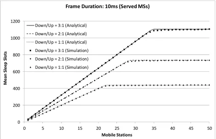
In order to examine the effect of the frame size in relation to the number of participating MSs on the number of sleep slots, we have also drawn the respective results considering 10ms and
20ms long frames. Since the 10ms long frame offers more OFDMA slots for data reception compared to the 5ms long frame, it provides more intra-frame sleep slots, as it is evident from
Fig. 14. Additionally, the larger resource bin allows the allocation of downlink slots to more MSs, as it is concluded from the number of unserved stations represented in Fig. 15. At this point, it should be noticed that in all cases, higher Downlink/Uplink ratios lead to fewer unserved
MSs, however, these MSs are associated with more sleep slots, because the larger downlink sub-frame allows transiting to sleep mode for longer periods. This fact becomes apparent for instance
0 200 400 600 800 1000 1200
0 5 10 15 20 25 30 35 40 45 50
M e a n S le e p S lo ts Mobile Stations
Frame Duration: 10ms (Served MSs)
Down/Up = 3:1 (Analytical)
Down/Up = 2:1 (Analytical)
Down/Up = 1:1 (Analytical)
Down/Up = 3:1 (Simulation)
Down/Up = 2:1 (Simulation)
[image:28.595.87.510.61.334.2]Down/Up = 1:1 (Simulation)
Fig. 14. Mean number of sleep slots of served MSs per DL sub-frame versus the total number of MSs, considering frame duration of 10ms and mean request size of 20 slots
0 100 200 300 400 500 600 700
0 5 10 15 20 25 30 35 40 45 50
M e a n S le e p S lo ts Mobile Stations
Frame Duration: 10ms (Unserved MSs)
Down/Up = 3:1 (Analytical) Down/Up = 2:1 (Analytical) Down/Up = 1:1 (Analytical) Down/Up = 3:1 (Simulation) Down/Up = 2:1 (Simulation) Down/Up = 1:1 (Simulation)
Fig. 15. Mean number of sleep slots of unserved MSs per DL sub-frame versus the total number of MSs, considering frame duration of 10ms and mean request size of 20 slots
[image:28.595.84.511.380.656.2]intra-Downlink/Uplink ratio, which provides the largest number of OFDMA slots for data reception, 50 MSs are not enough to reach the maximum number of intra-frame sleep slots. In more detail, as it shown in Fig. 17, the increased resource space is capable of allocating data regions even to
50 MSs, serving all bandwidth requests.
0 500 1000 1500 2000 2500 3000 3500 4000
0 5 10 15 20 25 30 35 40 45 50
M
e
a
n
S
le
e
p
S
lo
ts
Mobile Stations
Frame Duration: 20ms (Served MSs)
Down/Up = 3:1 (Analytical)
Down/Up = 2:1 (Analytical)
Down/Up = 1:1 (Analytical)
Down/Up = 3:1 (Simulation)
Down/Up = 2:1 (Simulation)
[image:29.595.89.509.197.471.2]Down/Up = 1:1 (Simulation)
0 20 40 60 80 100 120 140 160
0 5 10 15 20 25 30 35 40 45 50
M
e
a
n
S
le
e
p
S
lo
ts
Mobile Stations
Frame Duration: 20ms (Unserved MSs)
Down/Up = 3:1 (Analytical)
Down/Up = 2:1 (Analytical)
Down/Up = 1:1 (Analytical)
Down/Up = 3:1 (Simulation)
Down/Up = 2:1 (Simulation)
[image:30.595.88.510.61.333.2]Down/Up = 1:1 (Simulation)
Fig. 17. Mean number of sleep slots of unserved MSs per DL sub-frame versus the total number of MSs, considering frame duration of 20ms and mean request size of 20 slots
A general remark which becomes clear from the presented results is that the magnitude of the
conserved power depends on the downlink sub-frame resource space, the number of the requested slots and the number of the participating MSs. In Table II, we summarize the total
energy conserved in the whole network during a single downlink sub-frame, due to the intra-frame sleep slots associated with served MSs, considering the power consumption values adopted for WiMAX systems in [5-8] according to the specifications of [4]. As expected, the
more the participating MSs, the larger the available allocation space and the lower the Poisson λ
parameter, that is the mean request size, the greater the overall power savings observed are. The
reason for the increase of the sleep slots when more MSs participate in the network is the fact that each of the multiple MSs is capable of power saving, hence, increasing the total number of intra-frame sleep slots. On the other hand, a small number of MSs may just leave numerous slots
TABLE II.TOTAL ENERGY CONSERVED IN THE NETWORK DUE TO THE INTRA-FRAME SCHEME.
Network Energy Conserved in Sub-Frame (Joules)
Frame Duration 5ms (default) 10ms 20ms
DL-to-UL Ratio 1:1 2:1 3:1 1:1 2:1 3:1 1:1 2:1 3:1
30 MSs, λ = 1 3.396 4.684 5.971 8.547 11.123 13.699 18.85 25.29 29.583
30 MSs, λ = 50 0.632 1.253 2.071 4.296 7.309 11.109 21.071 37.952 46.084
1 MS, λ = 20 0.131 0.199 0.267 0.403 0.538 0.674 0.946 1.286 1.512
50 MSs, λ = 20 1.655 3.077 4.926 9.904 16.59 24.984 46.893 66.718 78.037
In order to further examine the impact of the resource bin dimensions on the intra-frame
power saving capabilities, we present results normalized to a specific resource space size. The presented results regarding the mean number of intra-frame sleep slots and the conserved power,
assume different frame sizes and different Downlink/Uplink ratios. Generally, the larger resource space is expected to allow more sleep slots, however, thoroughly comparing the intra-frame power saving capabilities of the different resource bin dimensions would require considering the
same time period. Towards this objective, we have normalized the number of intra-frame sleep slots incorporated in different sub-frame durations, assuming the same resource bin size that
corresponds to the 1:1 Downlink/Uplink 10ms long frame. The mean request size was set to 20 slots, whereas the total number of participating MSs in the network to 30. The respective results are graphically depicted in Fig. 18. It is evident that even when the same downlink sub-frame
duration is considered, the higher Downlink/Uplink ratio and the larger frame duration exhibit the greater number of intra-frame sleep slots, which are associated with served MSs. This is due
to the fact that the larger frames incorporate less overhead, which is related to control information, considered as portion of their total length. Hence, more OFDMA slots become available for mapping stations’ downlink requests, which then can save energy according to the
intra-frame power saving scheme. It is noticed that the differences for the three considered ratios of the 20ms frame are minor, attributed to the fact that almost all 30 MSs can be served by the
be clarified that the adoption of a large frame incorporates some significant drawbacks, too. First of all, stations are required to wait for longer periods to content for bandwidth in the following frame. This large waiting period may be proved critical for time-bounded traffic, such as voice
transmissions. Moreover, high frame duration leads to less frequent broadcast of beacon signals and control information, which could cause synchronization failures among stations.
Consequently, the selection of the suitable frame period in the range of 2ms to 20ms could be eventually considered as balancing between intra-frame power saving and communication flexibility.
0 100 200 300 400 500 600 700 800
5ms 10ms 20ms
N
o
rm
a
li
ze
d
I
n
tr
a
-F
ra
m
e
S
le
e
p
S
lo
ts
Frame Duration Down/Up = 1:1
Down/Up = 2:1
[image:32.595.86.511.294.536.2]Down/Up = 3:1
Fig. 18. Mean number of intra-frame sleep slots, normalized to the duration of 1:1 Down/Up DL sub-frame of the 10ms frame, for different frame periods, considering 30 participating MSs and
mean request size of 20 slots
6. Performance Comparison of Intra-Frame and Inter-Frame Power Saving Schemes
In this section, a comparative analysis on the power saving capabilities of the proposed
intra-frame scheme and the standardized inter-intra-frame scheme is provided. Our aim here is to evaluate the potential benefits of the technique analyzed in this work and quantify them against the
the percentage change of the power conserved using the intra-frame scheme in relation to the energy conserved by the inter-frame power saving technique.
It becomes evident from the description of the three power saving classes in Section 1, that
inter-frame power saving defines sleep periods of varying duration and frequency, that last for multiple frames, during which the involved MS transits to a low power mode without being able
to exchange data. The major advantage of intra-frame power saving is that MSs are capable of saving energy in the same frame that they exchange data. This strength of the particular method corresponds to data exchange completion in shorter time or equivalently to more conserved
energy in the same reference period.
On the ground that the examined intra-frame scheme takes place only during reception mode,
without loss of generality we assume that time is divided to downlink sub-frames. In the context of this analysis, we initially consider that a single MS participating in the network (Nr = 1) is scheduled for receiving D data bits via the BS downlink. These bits correspond to X requests for
an average of λ OFDMA slots per request, which are mapped to data regions in the resource bin of X downlink sub-frames according to vertical SPA. This means that if B bits are modulated per
slot, the following relationship exists:
, , , 0
D= X× × λ B X B∈Z+ >λ (20)
If we denote as T the total time being in sleep mode and L the duration of a slot, then the
equation below holds:
, ,
r
T = X×SS × ∈L X Z+ ∈L R (21) +
Assuming now that inter-frame power saving is adopted instead, the MS would require X
downlink sub-frames to complete data reception and an extra time interval T to transit to sleep
mode and conserve the same amount of energy that is saved by the intra-frame scheme.
Specifically, the intra-frame technique would require aggregate time X×F, whereas the
inter-frame method would require aggregate time X×F+T, where F is the employed inter-frame duration. In
one unit of time for both techniques. In more detail, the intra-frame method would conserve on average T×J/(X×F) watts, whereas the inter-frame method would conserve on average
T×J/(X×F+T) watts, where J is the power saved when in sleep mode compared to idle mode.
Hence, the intra-frame scheme achieves by T×J/(X×F) – T×J/(X×F+T) = T2×J/(X×F(X×F+T))
watts higher power saving. As a result, the percentage change of the power conserved using the
intra-frame scheme in relation to the power conserved by the inter-frame power saving technique is equal to:
(
)
(
)
(
)
2
1
, , , ,
F W L
F W L r
T J X F X F T T
C
T J X F T X F
R s E W
SS
X W F L
W R E W
= ×
= × + +
× × × +
= = →
× × + ×
× + × −
→ = ∈ ∈
+ Z R
(22)
The above quantity is plotted for different mean request sizes in Fig. 19, considering the default
frame length of 5ms. It is evident that intra-frame power saving greatly increases the amount of conserved energy per time unit compared to the inter-frame power saving. In more detail, the respective improvement is relatively low for small mean request sizes, due to the fact that in such
a case there is a high probability that the MS generates null bandwidth requests. Then, the maximum value is achieved for requests that occupy only one column in the resource bin and
allow for long inter-frame sleep periods. As the request size increases, the available slots for transiting to sleep mode decrease and so does the percentage change of conserved energy. Moreover, it is noted that the higher the Downlink/Uplink ratio is, the higher the percentage
0 0.1 0.2 0.3 0.4 0.5 0.6 0.7 0.8 0.9 1
0 10 20 30 40 50
P e rc e n ta g e C h a n g e o f C o n se rv e d P o w e r
Mean request size (slots)
[image:35.595.81.511.60.320.2]Down/Up = 3:1 Down/Up = 2:1 Down/Up = 1:1
Fig. 19. Percentage change of the power conserved using the intra-frame scheme in relation to the power conserved by the inter-frame power saving, considering 1 MS and default frame
duration 5ms
Lastly, it needs to be noted that intra-frame and inter-frame power saving schemes could be
easily and very effectively integrated. A station can be able of utilizing intra-frame power saving when actively participating in data exchanges within a frame, while in the long run it can adopt one of the intra-frame power saving classes depending on the exchange pattern of the
communicated traffic. A hybrid scheme like that would be capable to optimize energy conservation in a WiMAX network.
7. Conclusions
This paper presents a formal analysis of the intra-frame energy conservation capabilities of the widely known vertical SPA request mapping technique for the IEEE 802.16e downlink
sub-frame. The MSs are enabled to transit to sleep mode when being inactive, conserving this way significant amounts of energy. The number of the available sleep slots per downlink frame was estimated via the introduced mathematical formulae that take into account the number of
simulation program, which proved the soundness of the proposed analytic approach. The final results revealed the available number of sleep slots for varying network parameters and exhibited notable power saving possibilities, especially in the case of low bandwidth demands. Moreover,
the analytical comparison with the inter-frame power saving has shown significant improvement in energy conservation. Concerning our future plans, we intend to analyze the behavior of
various request mapping schemes under different multi-dimensional frame structures.
References
[1] IEEE 802.16e Workgroup, Part 16: Air interface for mobile broadband wireless access
systems—Amendment for physical and medium access control layers for combined fixed and mobile operation in licensed bands, February 2005.
[2] IEEE 802.16 Workgroup, Part 16: Air interface for fixed broadband wireless access systems—standard for local and metropolitan area networks, June 2004.
[3] J. Andrews, A. Ghosh, R. Muhamed, "Fundamentals of WiMAX, Understanding Broadband
Wireless Networking", Prentice Hall, 2007.
[4] Datasheet: SQN1130 System-on-Chip (SoC) for WiMAX Mobile Stations (2007). Sequans
Communications.
[5] Wong, G.K.W., Zhang, Q., Tsang, D.H.K. (2010). Switching cost minimization in the IEEE 802.16e mobile WiMAX sleep mode operation. Wireless Communications and Mobile
Computing, 10(12), 1576-1588.
[6] Hsu, C.-H., Feng, K.-T., Chang, C.-J. (2010). Statistical Control Approach for Sleep-Mode
Operations in IEEE 802.16m Systems. IEEE Transactions on Vehicular Technology, 59(9), 4453-4466.
[7] Wong, G.K.W., Zhang, Q., Tsang, D.H.K. (2009). Joint Optimization of Power Saving
[8] Hsu, C.-H., Feng, K.-T. (2009). A statistical power-saving mechanism for IEEE 802.16 networks. IEEE International Symposium on Personal, Indoor and Mobile Radio Communications (PIMRC 2009), 27-31.
[9] M. Katz and F. Fitzek, WiMAX Evolution: Emerging Technologies and Applications. Wiley Publishing, 2009.
[10] S.-L. Tsao, Y.-L. Chen, "Energy-efficient packet scheduling algorithms for real-time communications in a mobile WiMAX system", Elsevier Computer Communications, vol. 31, no. 10, pp. 2350-2359, June 2008.
[11] A. M. Baker, C. K. Ng, N. K. Noordin, A. Mustafa, A. Akbari, "An optimized energy saving mechanism in IEEE 802.16e Mobile WiMAX systems", Journal of High Speed Networks,
vol. 17, no. 3, pp. 147-161, Jan. 2010.
[12] M.-G. Kim, J. Y. Choi, M. Kang, "Adaptive power saving mechanism considering the request period of each initiation of awakening in the IEEE 802.16e system", IEEE
Communications Letters, vol.12, no.2, pp.106-108, Feb. 2008.
[13] Y. Ben-Shimol, I. Kitroser, and Y. Dinitz, "Two-Dimensional Mapping for Wireless
OFDMA Systems", IEEE Trans. Broadcasting, vol. 52, no. 3, pp.388-396, September 2006. [14] C. So-In, R. Jain, and A. K. Tamimi, "eOCSA: An Algorithm for Burst Mapping with Strict QoS requirements in IEEE 802.16e Mobile WiMAX Networks", to appear in the 2nd Inter. Conf.
on Comp. and Automation Engin. (ICCAE 2010), Feb. 2010.
[15] P. G. Sarigiannidis, G. I. Papadimitriou, P. Nicopolitidis, M. S. Obaidat, and A. Pomportsis,
"A Novel Adaptive Mapping Scheme for IEEE 802.16 Mobile Downlink Framing", IEEE Global Telecommunications Conference (GLOBECOM 2010), pp.1-5, 6-10 Dec. 2010.
[16] X. Perez-Costa, P. Favaro, A. Zubow, D. Camps, and J. Arauz, "On the Challenges for the
- 37 -
[17] S. Doirieux, B. Baynat, M. Maqbool, M. Coupechoux, “An efficient analytical model for the dimensioning of WiMAX networks supporting multi-profile best effort traffic”, Elsevier, Computer Communications, vol. 33, no. 10, pp. 1162-1179, June 2010.
[18] B. Baynat, G. Nogueira, M. Maqbool, and M. Coupechoux, “An Efficient Analytical Model for the Dimensioning of WiMAX Networks”, Networking 2009, Lecture Notes in Computer