Rochester Institute of Technology
RIT Scholar Works
Theses
Thesis/Dissertation Collections
1993
Automated generation of SW design constructs
from Mesa source code
David Egerton
Follow this and additional works at:
http://scholarworks.rit.edu/theses
This Thesis is brought to you for free and open access by the Thesis/Dissertation Collections at RIT Scholar Works. It has been accepted for inclusion
in Theses by an authorized administrator of RIT Scholar Works. For more information, please contact
.
Recommended Citation
THESIS
FINAL
REPORT
VOLUME I
SUBJECT:
AUTOMATED
GENERATION OF SW
DESIGN
CONSTRUCTS
FROM MESA
SOURCE
CODE
AUTHOR:
DAVID
EGERTON
DATED:
4Q1993
REVISION:
1.1
Rochester Institute of Technology - Masters Degree Program
School of Computer Science
Automated generation of SW design constructs
from Mesa source code:
by
David Egerton
A thesis submitted to the School of Computer Science
in partial fulfillment of the requirements of the degree of
Master of Science in Computer Science.
Approved
by:
Professor Alan Kaminsky
Professor James HelJotis
PrOfessor Peter Anderson
TABLE
OF CONTENTS
VOLUME
I
Verl.l
1.0 INTRODUCTION AND BACKGROUND
1.1 Problem
statement
1.1.1
Introduction
1
1.1.2
Design
representation
2
1.1.3
The Mesa
language
6
1.1.4
Reverse
Engineering
11
1.1.5
Scope
18
1.2 Previous
work
1.2.1
Focused
articles
21
1.2.1.1
History
21
1.2.1.2
Representation
Schemes
26
Data Flow Diagrams
26
Structure Charts
30
1.2.1.3 Extraction from
code
35
1.2.1.4 Commercial
graphics
41
McCabe
41
CADRE Teamwork
45
1.2.1.5 Data dictionaries
49
1.2.2
Search
process
53
1.3 Theoretical
and
conceptual
development
1.3.1
Structure
charts
55
Mesa
file types
55
Developing
the
rules
58
Data Structure Extraction
62
1
.3.2Data Flow Diagrams
65
1.3.3
Data Dictionaries
71
1.3.4
Comment information
72
Rochester
Institute
of
Technology
-Masters Degree Program
School
of
Computer Science
2.0
PROJECT DESCRIPTION
2.1 Functional
specification
2.1.1
User Interface
76
2.1.1.1
The herald
window
76
2.1.1.2 The feedback
window
76
2.1.1.3 The
control window
76
2.1.2
Inputs
84
2.1.3
Outputs
86
2.1.3.1
Extractor.data
86
2.1.3.2 StructChart.data
88
2.1.3.2.1
Graphical
output
90
2.1.3.2.2
Tabular
output
92
2.1.3.3
DataFlow.data
94
2.1.3.3.1
Variable
table
output
94
2.1.3.3.2
Tabular
output
97
2.1.3.4 Generic front
sheet
99
2.1.4
Limitations
and restrictions
101
2.1.4.1 System limitations
and restrictions
101
2.1.4.2 Performance
expectations
101
2.1.5
System Files
102
2.2 System
specification
2.2.1
Foundational design
philosophies
103
2.2.2
System Data Flow Diagrams
105
2.2.2.1
Keyboard
controller
107
2.2.2.2 Window
controller
108
2.2.2.3 File
controller
108
2.2.2.4
Clear database
108
2.2.2.5 File
parser
109
2.2.2.6
Display
controller
110
2.2.2.7 Message handler
112
2.2.2.8
Outputs
112
2.2.3
System Data
Dictionary
113
2.2.4
System Organisational Chart
116
2.2.5
Equipment Configuration
118
2.2.6
Implementation tools
118
2.2.7
Known bugs
118
3.0 CONCLUSIONS & FINDINGS
3.1
A
Study
of
the
outputs
120
3.1.1
SCGraph
'.
120
3.1.2
Comments
125
3.1.3
SCTable
127
3.1.4
DFDTable
128
3.1.5
DFDVariable
135
3.1.6
Extractor.data
136
3.2 Comparison
to
the
theory
136
3.2.1
The IEEE
standard
137
3.2.2
Rules
for
Structure Chart
creation
139
3.2.3
Comparison
to
Data
Flow
extraction
theory
140
3.2.4
Comparison
of raw
data
extraction
to
theory
143
3.3 Discoveries
along
the
way
144
3.3.1
Advantages
to the
Maintenance Programmer
144
3.3.2
Observations
148
3.3.3
Enhancement
opportunities
150
3.3.4
Concluding
paragraphs
154
4.0
BIBLIOGRAPHY
Rochester Institute
of
Technology
-Masters Degree Program
School
of
Computer
Science
ILLUSTRATION
LIST
Figure 1.1.3
Mesa interface
structure
representation
8
Figure
1.1.4
-Reverse
Engineering
and
Forward
Engineering
14
Figure
1.2.1.2.1
Simple
Data
Flow diagram illustration
28
Figure 1.2.1.2.3
-Level 1
Data
Row diagram
29
Figure
1.2.1.2.4
Structure
Chart initial
example
31
Figure 1.2.1.2.5
-Structure
Chart derived from
our system
DFD
33
Figure 1.2.1.2.6
-Structure Chart
with
Data
Rows indicated
34
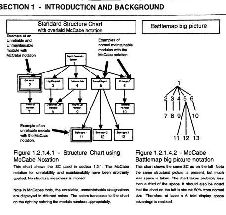
Figure 1.2.1.4.1
Structure Chart
using
McCabe
notation
44
Figure 1.2.1.4.2
McCabe
Battlemap big
picture
notation
44
Figure 1.2.1.4.3
-Cadre Ada
Structure
Chart
Representation
47
Figure 1.3.1
-Mesa
code
implementation
example
56
Figure
1.3.2
-Subordinate relationship
of
imported
procedures
60
Figure 1.3.7
-Highest
level DFD for
ACIgnitionlmpl
68
Figure 1.3.8
-Main
procedure
level DFD
69
Figure
1.3.9
Lowest
level DFD
for
the
Ignite
procedure
70
Figure
2.1.1
DesignExtractor
screen
view with all
outputs
open
75
Figure 2.1.1.1
-DesignExtractor
screen of one
file
parse
79
Figure 2.1.1.2
DesignExtractor
screen of a
display
session
80
Figure 2.1.1.3
DesignExtractor
screen
of conflict
message
81
Figure 2.1.1.4
DesignExtractor
screen
of raw
data
dump
82
Figure 2.1.1.5
-DesignExtractor
screen of
multiple
file
parse
83
Figure 2.1.3.2.1
Output file
example,
missing
export
data
89
Figure 2.1.3.2.1.1
-Output file
example,
SCGraph
91
Figure
2.1.3.2.2.1
Output
file example,
SCTable
93
Figure
2.1.3.3.1.1
-Output
file example,
DFDVariable
96
Figure 2.1.3.3.2.1
-Output file example,
DFDTable
.98
Figure
2.1.3.4.1
Output
file example,
generic
file
listing
100
ILLUSTRATIONS
LIST
CONTINUED
Figure
2.2.2.1
-DesignExtractor Context Diagram
106
Figure
2.2.2.2
DesignExtractor
Level
0 DataFlow
Diagram
107
Figure
2.2.2.3
-File Parser Level 1 DFD
109
Figure 2.2.2.4
-Display
level 1 DFD
Ill
Figure 2.2.4.1
-Structure Chart
of
Design Extractor
117
Figure
3.1.2.1
-Example
of
comments
with
Hypertext
126
Figure 3.1.4.1
Hypertext
variable pullout
129
Figure
3.1.4.2
-Context
level DataFlow Diagram
131
Figure 3.1.4.3
Level 1 Data Row diagram
example
132
Rochester Institute
of
Technology
-Masters Degree Program
School
of
Computer Science
TABLE LIST
Table
1.1
Table
1.1.4
Table 1.2.1
Table 1.2.1.5.1
Table
1.2.2.1
Table 1.3.1
Table 1.3.2
Table 1.3.4
Table 1.3.5
Table 1.3.6
Table 2.2.1
Table
2.2.3.1
Table
3.2.1.1
Table 3.2.2.1
Table 3.2.3.1
Table 3.2.4.1
Recommended
design
views
5
Analysis
of source
code,
design
extraction
expectations
....16
Rules for constructing Data Flow diagrams from Pascal
....38
Data
Dictionary
notation
symbols
51
Document
search statistics
54
Rules for creating
standard
Structure
Chart Representation
..61Data fields
required
for Structure
Chart
creation
64
DFD
extraction
IGNITE data descriptor
table
66
DFD
extraction
AUDITIGNTTE data descriptor
table
67
Data
Dictionary
example
from
ACConfig
72
Overview
of
the
parser
104
DesignExtractor Data
Dictionary
115
Comparison
table to
IEEE
standard
138
Comparison
table
of
Structure
Chart
creation rules
139
Data Flow
theoretical
rule comparison
142
Comparison
of
data
extraction with
theory
143
TABLE
OF CONTENTS
CONTINUED
VOLUME II Verl.O
APPENDICES
Appendix A
Output
listings
A.l
Extractor, data
A.2
StructChartdata
A.2.1
SCGraph
A.2.2
SCTable
A.
3
DataFlow. data
A.3.1 DFD Variable
A.3.2 DFD
Table
Appendix B
Source
code
listings
B.
1
Configuration
file
B.2
Interface
files
B.3
Program
files
Appendix
C
PGS Grammar
Appendix D
Variable
types
Appendix
E
Variable
scopes
Appendix F
Repeats
Appendix
G
List
types
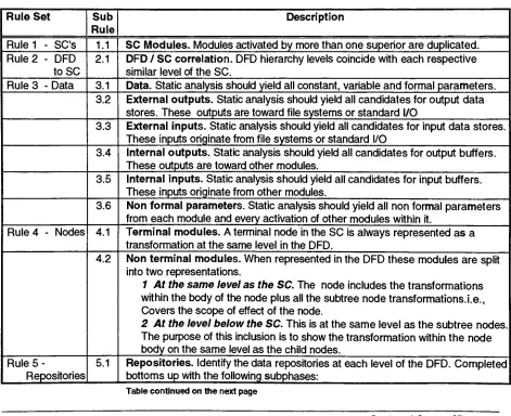
SECTION
1
-INTRODUCTION
AND
BACKGROUND
1
.0INTRODUCTION
AND BACKGROUND
This
section
is
split
into five
major categories.
The introduction
section which
outlines
the basic
premises
of
the
problems
to
be
tackled,
the
Design Representation
section
which
details IEEE
standard
representation
guidelines
for
design,
the
Mesa Language
section
which
introduces
the
Xerox proprietary programming
language,
the
Reverse
Engineering
section
bringing
focus to
the
concept of
extracting
design
information
from code,
and
finally
a section
detailing
the
scope of
the thesis.
1.1
Problem
statement
The introduction
section
below,
in
conjunction with
the
scope section
(1
.1.5),
details
the
essential elements
of
the
items
of
emphasis
for this thesis.
1.1.1
Introduction
This
thesis
is
concerned with
the
Reverse
Engineering
of
Mesa
code.
Mesa is
a
programming
language
used
by
the
Xerox Corporation
especially
designed for
ultra
large
scale
software
projects.
Many
Xerox
projects
have
considerable
amounts of code
already developed
and
in
service with
very little up
to
date
design documentation. The
maintenance
phase of
Software
requires
that
updates
will occur
continuously
in
response
to
customer
demands. Software
engineers,
often not
the
original
designers,
will need
to
gain a
thorough
understanding
of
the
code
to
make reliable changes.
This
thesis
proposes
to
outline
Software
tools
developed
in Mesa
that
will extract
design information. The
extracted
information
should
be
suitable
for the
graphical
and
tabular
representations of
architectural
constructs.
The tools
will
be
written and applied
originally to
a small portion of a current project.
These
will
serve
as
prototype
for tools that
could
be
scaled
up
to
parse several
hundred
thousand
lines
of
code.
Clearly,
not
all
design information
is
available
from
the
code.
The
theory
section of
the thesis
will
develop
an
understanding
of
the
design documentation
expectations
and compare
these to the information that
can
be Reverse
Engineered
from
code.
1.1.2 Design
Representation
The IEEE has
developed
a
design
standard
for
software
.This is
one
of
the
major reference
sources of
design
expectations.
The
original charter
for
this
endeavor
was approved on
September 22 1983 [# 26]. The
standard
was
developed
by
committee
meetings and
working
groups
involving
many
members
from
top
companies
in Software
development,
AT&T,
IBM
and
Digital to
name
but
a
few.
The
standard
then
represents a useful
indication
of
the
expected
content of software
design information in
industry
today.
The final designation for the
standard
is
IEEE Std 1016-1987
which was approved on
March
12,
1987.
Section 5
of
the
IEEE
standard
identifies the
minimum set
of
design
documentation
that
should
accompany
a software
product.
This
thesis
deals
with
design information
that
can
be
retrieved
from
code.
We
will use
the
IEEE
recommendations
as a guide
to
establish
the
items that
should
be
present within a software product
(code
and
documentation)
and compare
this to the
documentation
available
by
automatic
extraction.
This
approach
may
also yield recommendations
for
changes
to
source code
development
standards
that
will
better
align
the
automatically
extracted
set with
the
IEEE
set.
The IEEE
standard
defines
a software
design
description
as
follows:
"A
software
design description is
a representation or model of
the
software
system
to be
created.
The
model should
provide
the
precise
design information
SECTION
1
-INTRODUCTION
AND
BACKGROUND
needed
for planning, analysis,
and
implementation
of
the
software system.
It
should
represent a
partitioning
of
the
system
into design
entities
and
describe the
important
properties
and relationships
among those
entities
[Sec
5.1
page
10]."The
standard goes on
to
further describe
the
need
for
attributes
for
each
design
entity.
The
purpose
of
this
is to
enable a method of
reducing the
software project
into
manageable pieces
(design entities)
and
then
provide a consistent method of
describing
each piece.
The
intent is
not
to
define
methodologies or method of
description
but to
ensure
that
a software system can
be
expressed as a collection of
design
entities,
each
possessing
properties and relationships.
These
properties and relationships are
the
attributes
which should
be
present
with each
design
entity.
The
following
list describes
each of
the
required minimum set of attributes.
Identification [from
section
5.3.1].
The
name of
the
entity.
Each design
entity
must
have
a unique
identifier.
Type [from
section
5.3.2]. A
description
of
the
kind
of entity.
For
example
subprogram,
module, procedure, process,
or
data
store.
Purpose
[from
section
5.3.3]
A
description
of
why
the
entity
exists.
This
section
should
designate the
functional,
performance and
any
special requirements.
Function
[from
section
5.3.4]
A
statement
of
what
the
entity does. The
type
of
transformation
performed on
data
by
this
entity
or
type
of
data
stored.
Subordinates
[from
section
5.3.5]
The identification
of all
entities
composing
this
entity.
Indicates the
parent/child
relationships
in
the
design
decomposition.
Dependencies
[from
section
5.3.6]
A description
of
the
relationships
of
this
entity
with other entities.
Often
depicted
in
Data Flow Diagrams
(DFD),
Structure
Charts
(SC)
and
Transaction
Diagrams (TD). The interactions
may
involve the
initiation,
order of
execution,
data sharing, creation, duplication
usage, storage,
or
destruction
of entities.
Interface [from
section
5.3.7]. A description
of
how
other entities
interact
with
this
entity.
These interfaces deal
with
the
methods of
interaction. Such items
as
communication
via
parameters,
common
data
area or
messages, direct
access
to internal
data,
input
and output
meanings,
acceptable
ranges,
formats
and error
codes.
Resources
[from
section
5.3.8].
A
description
of
the
elements used
by
the
entity
that
are external
to
the design. Information
such as physical
devices
(printers.disc
partitions,
memory
banks)
software services
(math
libraries,
operating
system
services,
and
processing
resources
(CPU
memory
cycles,
memory
allocations,
buffers).
Processing
[from
section
5.3.9]. A description
of
the
rules used
by
the
entity
to
achieve
its function. Such items
as
timing,
sequences of events or
processes,
prerequisites
for
process
initiation,
priority
of
events,
processing
level,
actual
process
steps,
path
conditions,
and
loop
back
or
loop
termination
criteria.
Data [from
section
5.3.10]. A description
of
the
data
elements
internal
to
the
entity.
Describes
the content,
structure and
use of
data
elements.
Includes
such
items
as method of
representation,
initial
values, use, semantics,
format,
and
acceptable values of
internal data. Some
examples are
file structures,
arrays,
stacks,
queues,
and
memory
partitions.
Typically
described in data
dictionaries.
SECTION
1
-INTRODUCTION
AND
BACKGROUND
The
definitions
above
are an abridged version of
those
described in IEEE Std 1016-1987.
Readers
who require
the
complete
treatment
should refer
to the
body
of
the
standard.
Section
6
of
the
IEEE
recommendations
introduces the
concept
of
design
views.
They
are
a
method of representation of
the
design
attributes
described
above.
The
table
below
[table 1
page
13
of
the
standard]
is
a
fairly
self
explanatory mapping
of
design
views
to design
attributes and
example
representation
formats.
Design
view
Scope
Entity
attribute
Example
representations
Decomposition
description.
Partition
of
the
system
into design
entities.
Identification,
type.purpose,
function,
subordinates.
Hierarchical
decomposition
diagram,
natural
language.
Dependency
description.
Description
of
the
relationships
between
entities and system
resources.
Identification,
type,
purpose,
dependencies,
resources.
Structure charts,
Data
flow
diagrams,
transaction
diagrams.
Interface description
List
of
everything
a
designer.or
tester
needs
to
know
to
use
the
design
entities
that
make
up
the
system.
Identification,
function,
interfaces.
Interface
files,
parameter
tables.
Detail description.
Description
of
the
internal design details
of
an entity.
Identification,
processing, data.
Flowcharts,
N-S
charts, PDL
Recommended
design
views
-Table
1.1
(
Table
1
page
13
of
IEEE Std
1016-1987)
This
concludes
this
section
of
the
IEEE treatise.
The
purpose of
the
section
has been to
introduce
the
reader
to
the
standard
expectation
for
software
design documentation. These
guidelines
will
be
referred
to throughout the thesis providing,
wherever
possible,
an
understanding
of
the
strengths of
Reverse
Engineering
and
its
weaknesses compared
to
these
IEEE
expectations.
It
should
already
be
apparent
that these
recommendations
deal
with
the
Forward
Engineering
situation.
Therefore
some
items
expected
for this
purpose will
clearly
not
be
available when
Reverse Engineered. Section 1.1.4 "Reverse
Engineering"will
deal
with
this
aspect
in
more
detail.
1.1.3
The Mesa language
Mesa is
a
Xerox proprietary
software
programming language particularly
suited
to the
development
of
ultra
large
programming
projects.
This language has been in
use
in Xerox
communities
throughout the
1
980's
and
has
spumed a
number of significant software products.
Many
people are
familiar
with
the
Xerox line
of workstations and
the
high quality document
processing
software
Viewpoint
and
Globalview;
these
products are written
in
the
Mesa language.
Many
of
Xerox's
electronic printer products also use
Mesa,
which
is
an
ideal language for this
type
of
demanding
real
time
application.
The
tools
written
for
this thesis
are also written
in
the
Mesa language
using
XDE (Xerox Development
Environment)
as
the
tool
workbench and
operating
environment.
Mesa
is
a
very
powerful
language. The language has many
similarities
with
Pascal
including
the
attractive
feature
of user-defined
data
types
that
enables
data structuring
capability
and
data
abstraction.
[# 45].
Mesa, however,
extends
the
capabilities of
Pascal
to
make
ft
eminently
suitable
for the
creation of
ultra
large
software projects with multiple co-operative
development
personnel
working
congruently.
The
Mesa Course book
states
it like this:
SECTION
1
-INTRODUCTION
AND
BACKGROUND
"Standard Pascal
does have
significant
shortcomings
in
terms
of
writing
a
large
system:
there
is
no
way
to
break
the
system
down into
small
separately
compiled
units and
then
integrate
them
into
a
consistent whole.
This
prevents
the
compiler
from
checking
the type
correctness of actual parameters
in distinct units, inhibits
the
development
of
"libraries"to
extend
the
language,
and
generally
complicates
the
implementation
of
large
systems constructed
by
a
group
of programmers.
Further
more,
standard
Pascal does
not support
dynamic
array
bounds:
it
is
difficult to
write general routines
that
process arrays of
different
sizes.
Standard
Pascal has
no exception
handling
facilities
and
does
not support concurrent
processes."
A
number of
interesting
items
are mentioned
in the
paragraphs above.
We
will expand on
these
briefly
to
ensure
we understand
the
importance
of
the Mesa
differences.
First the
"Strongly
Typed"concept.
The Mesa
compiler
is
sensitive
to the type
checking
of
data
items in different programming
units.
Programmers
can
develop
separate
modules and
then
bind
them
as part of
the
compilation process.The
binder
enforces
the
strong
type
checking.
Thus
modules
will not
have
type
mismatches
from inconsistent declaration
of
data types.
Comparatively,
Pascal
programs either need
to
be
one monolithic program
and,
therefore,
ensure
data
types
are
consistent,
or
break down their
programs
into
multiple smaller modules
introducing
the
inherent
risk of
unreliability
due to data type
mismatches.
Secondly
the "block
structured"concept.
Mesa
has significantly
more modularization
power
than
Pascal.
Interfaces
and
program modules are an
inherent
structural
part of
the
language. The
interface has
no executable code.
Its
purpose
is
to
collect
together
classes of objects
into
an
abstraction.
It
also provides
the
vehicle
for
the
type
checking
facility
described
earlier.
The
interface declares
the
imports
and exports of modules external
to the
abstraction,
it defines
and
provides
the
boundary
of operation
for
modules
that
do
not export.
Types,
constants and
procedure
headers
can all
be
declared
within
the
interface. The interface
contains
the
information
to
allow
the
compiler
to
type
check
and ensure
that
program module
implementations
are present
and
that
data types
are consistent.
The
implementation
modules are where
the
computational
implementation
code
is
written.
Implementation Modules
can
only
service clients when accessed
through the
interface definitions. These
are
bound
at compile
time.
The
interface,
once
declared,
allows programmers
to
work on
the
implementation
module without
affecting
client
implementation
work which can go on
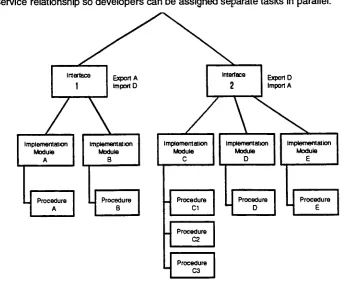
independently. Thus information
hiding
is facilitated
by
the
client
/
service
relationship
so
developers
can
be
assigned separate
tasks
in
parallel.
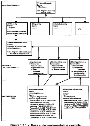
Interface
1
Export
A
Import
0
/
/\
V
Implementation
Module
A
Implementation
Module
B
Procedure
A
Procedure
B
Export D
Import
A
Implementation
Module
C
Procedure
C1
Procedure
C2
Procedure
C3
Implementation
Module
D
Implementation
Module
E
Procedure
D
Procedure
E
FIGURE
1.1.3
-Mesa interface
structure
representation
[image:18.562.125.471.371.655.2]SECTION
1
-INTRODUCTION
AND
BACKGROUND
The diagram
above
[Figure
1
.1.3}
shows a simple representation of
the
interface /
implementation
module concept.
Implementation
modules
that
are not on
the
export
list
can
only
be
used
within
the
scope of
the
parent
interface,
i.e.,
Implementation
modules
C,D
and
E
can
all
access each other as
clients
or services within
the
confines
of
Interface 2. Access
external
to
Interface
2
can
only
occur
if
an explicit export clause
is defined. As the diagram
shows
there
are
implementation
modules
that
can
be
exported
beyond the
confines of
Interface 2. Module D is
shown as
exportable
by
declaration
of an export clause within
Interface 2. Note that Interface 1
has
to
have
a
complementary
Import
clause
to
enable
the
client service
relationship to be
established.
With the diagram
as
shown,
procedures within
module
D
can
be
accessed
by
modules
B
and
C if
required.
Similarly
the
Module A is
accessible
to the
Interface 2
modules.
Modules C
and
E
are not exportable
beyond Interface 2
and module
B is
not exportable
beyond
Interface 1
,because
no export/import clauses are present
in
their
respective
interface
modules.
This
export
capability is only
true
if
the
procedures within
the
implementation
modules are
declared 'public'. If the
procedures
are
'private'then
a
further
constraint on
accessibility
holds.
In
this
case procedures are
only
available
to
other procedures within
that
single
implementation
module.
This is illustrated
by
implementation
module
C
where several
procedures
are
indicated.
If
these
procedures are
declared
as
'private'then
access control
is limited to
within
the
implementation
module
C. In this
case
procedures
C1
,C2
and
C3
cannot
be
accessed outside
of
the
implementation
module
C boundary.
Therefore
module
D
and
E
will
have
no access
capability
to
procedures
within
module
C.
Thus levels
of
abstraction
and
confinement
of
scope
similar
to the
constructs
of structured
design
can
be
represented
well
in the Mesa language
through
careful choice of
import /
export
access controls.
Mesa
also provides
facilities
for
handling
exceptions.
Mesa
uses signals which can
be
raised
when
an
invalid
condition occurs.
For
example,
invalid inputs
and
allocators out of space are
exception
conditions.
Exceptions
are
dealt
with
by
use of
'handlers'.
These
are written
in
a
distinctive
syntax
known
as
'catch
phrases'which
execute
a user
defined
clean-up
sequence
when exceptions occur.
When
a signal
is raised, the
Mesa
run-time controller searches
for
the
handler in the
current procedure.
If it does
not
find
a catch
phase, it
will
travel up the
call stack
to
the
next
one,
and so on
up the
call
stack until
it finds
a valid
handler. Uncaught
signals can cause
ambiguous system operation and
therefore,
to
minimize risk of
unreliability,
care must
be
taken to
provide catchall routines
to
handle
unforeseen situations.
Mesa
also
has
some
very
powerful concurrent
processing
capabilities.
The keyword FORK
enables
a second process
to
start
executing in
parallel with
the
one where
the
FORK
command
occurred.
Multiple
processes can
be
running concurrently
in
a single system
using
this
feature.
Many
procedures can
FORK
off new processes all
running
together
in
parallel.
On
occasion,
however,
programmers
may
desire
that
concurrent processes
come
together
again at some
convenient point.
A
good example of when
this
might
be
needed
is
when a program wants
to
perform a
heavy
mathematical calculation.
The first
process
FORKS
off a second
procedure
to
complete
the
computation
while
the
first
process continues
to
operate on other
data. After
a short
time the
mathematical computation completes and a rendezvous with
the
first
process
is
required.
A
JOIN
command accomplishes
this.
Thus the keyword JOIN
can
be
used
to
enable
the
synchronization of concurrent processes.
When two
processes are
running
after
a
FORK,
then
a
JOIN
will cause whichever process completes
its
computation
first,
to
wait until
the
other
process
has
completed
execution,
and
then
'join'the
two
concurrent
processes
back into
a
single
SECTION
1
-INTRODUCTION
AND
BACKGROUND
executing
process
once
again.
Concurrent
processes can share
the
same
data
address
space
and global variables.
Thus
a
mechanism
to
prevent
data
conuption must
be
provided
if
integrity
is
to
be
maintained.
Mesa
uses
the traditional
form
of
monitors,
including
the
monitor
lock
facility
for
ensuring
proper mutual exclusion
and protection of
data in
concurrent situations.
Mesa therefore is
a
very
powerful
language for large
scale
development
of embedded real
time
systems.
The
strong
type checking,
package
body
/ interface
structure
and extensive
concurrency
capabilities
make
it
eminently
suitable
for the design
of embedded control systems
such
as
those
in
electronic
printer products.
These
products
require
massive
amounts of
computational
power
in
small
time
slices
constrained
by
the
process speed required
to
produce
complex
laser images
on
fast moving
paper.
Concurrent CPU's
executing
concurrent
program
code are often employed
to
achieve
these
demanding
goals.
Mesa
provides
the inherent
capabilities
to
do this
effectively.
Also,
large
programming
teams
can work
together in
relative
independence using the Mesa language
and
the
XDE
networked environment.
The
powerful
abstraction
feature
provided
by
the
interface /
implementation
module concept
is ideal for this
purpose.
Mesa has
proved
to
be
a
very
effective
tool
and
thus
has large
amounts
of product code
already
existing in
products
currently
marketed
by
Xerox
1.1.4 Reverse
Engineering
Reverse
Engineering
has its
origin
in the
world
of
hardware
[# 14]. The
idea is
to take
existing
designs
and
figure
out
their
strengths and
weaknesses.
In
military
situations, this
can
ensure
that
you
maintain national
security
by
understanding
your enemies equipment
and
staying
ahead.
In
the
commercial
world, this
provides a competitive
advantage
leading
to higher
return on asset
and a
larger
market
share
over
time.
In
software
,Reverse
Engineering
can
be
applied
for
exactly
these
reasons.
However,
the
more
usual event
is the
pursuit
of maintenance objectives.
Reverse
Engineering
is
the
part of
the
software
lifecycle
that
allows one
to
reconstruct code
for
the
purpose of
adding
new
features
or
improving
an
existing
design. Reverse
Engineering
however is
not
normally
condoned,
it
is
an
exception
case where proper
documentation
is
not available.
The
second
process,
improving
on
existing
design,
is
called
Re-Engineering. Although
a
very
closely
related
topic,
it
will not
be
included in
our
discussions for
the
reasons
discussed in the
next paragraph.
What
then
is
Reverse
Engineering? Reverse
engineering
is defined
in the
article
'Reverse
Engineering
and
Design Recovery:
a
Taxonomy
[
#
14
]
in
the
following
way:
Reverse
Engineering
is
the
process of
analyzing
a subject
system
to
-Identify
the
system's components and
their
interrelationships
and
-To
create representations of
the
system
in
another
form
or at a
higher level
of abstraction.
Reverse
Engineering,
then,
does
not
involve changing
the
subject system or
creating
a new
system
based
on
the
reverse-engineered subject's system.
It is
a process of
examination,
not a
process
of change or replication.
Of
course,
having
made
this caveat,
many
of
the
outputs of
Reverse
Engineering
are
eminently
suitable
for the
purpose of
Re-Engineering.
Many
CASE
tool
vendors
are
beginning
to
bring
together
all
three
concepts,
Forward
Engineering
(the
usual
design
process),
Reverse
Engineering
and
Re
Engineering. The
article
A CASE for
Reverse
Engineering
[#
5]
puts
it
like
this:
SECTION
1
-INTRODUCTION
AND
BACKGROUND
"In
targeting
the
maintenance,
enhancement,
and migration of
existing
application
systems, the
next generation of
CASE
products must open
the
door
to
a more
reflective,
cooperative mode of
development. Such
a
design
process
is
not
the
one
way
street
of
top
down
design,
but
assumes a give and
take whereby
changes
can
be
propagated
up
and
down
at
any
point
in
the
design
process.
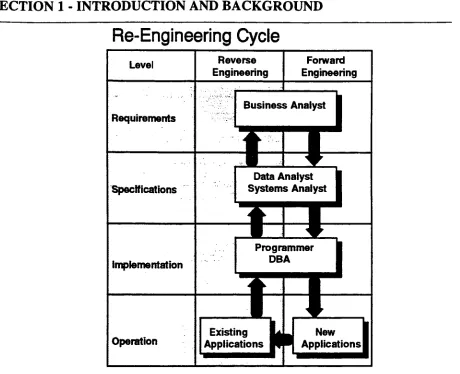
The
Re-Engineering
cycle chart
below
provides an architectural view of
this
new
CASE
world,
which
features both Forward
and
Reverse
Engineering."The
relationship
between
these three
fields is
clearly
indicated in
the
diagram below
taken
from
the
CASE for Reverse
Engineering
article:
Re-Engineering
Cycle
Figure 1.1.4
-Reverse
Engineering
and
Forward
Engineering
This diagram
shows
the
close
relationship between
the
two
available
directions
of
travel.
Forward
Engineering,
going
through
the
traditional
channels of
Requirements,
Specification
and
Implementation
on its
way
to
active
use
in
customer
hands.
Reverse
Engineering,
a
return
journey
from Implementation back
to
requirements.
When in
operation
the
software
is continually
enhanced,
usually in
response
to
customer
demands.
The "new
applications"often
come
in
at
the bottom
as
shown,
and
the
temptation
is for the
programmer
to
'enhance'the
product at
that
level. Enhance is
emphasized
because
often
the
outcome
is degradation.
Many
organizations
are
SECTION
1
-INTRODUCTION
AND BACKGROUND
not equipped
to
go
backwards up
the Reverse
Engineering
track
and, consequently,
system
architectures start
to
suffer
from
the
patch syndrome.
Patches
are analogous
to
'band-aid'where
the
purpose
is
to
fix up
the
product
temporarily.
No
attempt
is
made
to
consider
the
original
specifications
or
requirements
to
see
how the
change
(patch)
affects
the
system
as a whole.
Consequently
the
patch
may
work
well
for
the
one particular
fix in
mind
but
side effects of
the
change
may
occur.
As
other
patches
to
fix further
problems are
added
the
architectural
integrity
of
the
product starts
to
disintegrate. The
rules
for the higher levels
of abstraction are
violated,
data
structures are
kludged
and system
interactions
become
erratic.
Patching
in
this
fashion
will,
eventually,
lead to
forced
system retirement
because
the
cost of
fix
and side effect removal
becomes
increasingly
expensive
as structural
integrity
diminishes.
Reverse
Engineering
then
provides
the
opportunity
to travel
back up toward the
requirements
when original
design
documentation
is
unavailable.
Thus
systems can
be
studied at
the
abstract
level
of
design
and requirements
to
ensure
that
system
integrity
can
be
properly
maintained
as
changes occur.
An
ideal
system
would achieve
this.
However,
the
state of
the
art
today
allows us
to travel up only to
the
specification
level in the main,
unless
extraordinary
efforts
have been
made
to
document
the
source code with
requirements
issues
included
in the
comments.
This is
not
usually done
nor
thought to
be
beneficial.
With
this
model
in
mind,
we are now
about
to
start
the
journey
of
understanding
how
far
we can
travel
backwards into the
specification
from the
source
code.
Clearly,
many
assumptions
made at
design
time
guide
the
structural
makeup
of
any
operational software product.
Much
of
this
information
cannot
be
captured
from the
code.
The
type
of
system
modelling
at
this
level does
not
map
well
into
code comment
structures
and,
therefore,
is
documented
at
higher levels
of
abstraction.
Indeed,
the traditional
Forward
Engineering
model encourages
this kind
of
information
to
be kept
separate
from
the
code.
However,
there
is
a great
deal
of
information
that
can
be
extracted
directly
from
the
code.
Process
names, structure, data
flow,
data type
/
structure
are all examples of what can
be
recaptured
by
Reverse
Engineering.
Creation
of
a
toolset
needs
to
focus
on
this
information to
determine
its
availability
for
automatic extraction
from
source.
What
then
can
be drawn from the
code
in the
case
of
Mesa? This
question will
be
answered
by
considering
the
expected
minimum
set of
design
documentation
expectations
from
section
1
.1.2evaluating
the
potential candidates versus
those
items
that
will not
be
extractable
in
any
automated
form. The thrust
of our
thinking
at
this
stage
is
automation.
What
software
tools
can
be
written
to
extract
the
data
required
for
the
specification reconstruction.
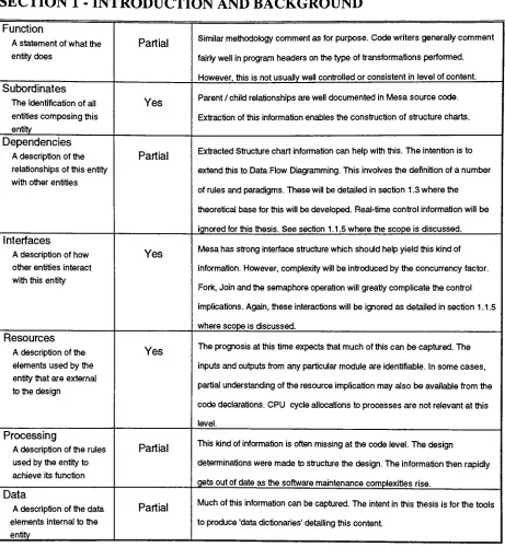
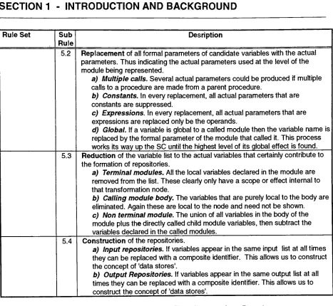
The table that follows
evaluates each
design
attribute
in
turn,
projects an expectation
for
extractabilrty
and
follows
through
with an explanation of
the
reasons
for
this
projection.
Design
attribute
Extractable
Explanation
Identification
The
name of
the
entity
Yes
Mesa
code
has
distinct
syntax
for procedures,
implementation
modules and
configuration
files. These
can
be
extractable automatically.
Type
A
description
of
the
kind
of
entity
Yes
Procedures
and modules areclearly defined
in
Mesa.
The
interfaces
willhelp
usdifferentiate
between
subprograms,
full
modules,
procedures,
processes and
data
stores.Purpose
A description
ofwhy
the
entity
exists
Partial
The intent
here
is
to
study
the
contentof
the
comments section of each module
and
interface.
This
should yieldinformation
that
is
relevant
to the
details
of
function,
performanceand
special requirements.Perhaps
agood
Reverse
Engineering
practice would
be
to
include
special code
commenting
structures
to
facilitate
automatedidentification
of relevantfields.
SECTION
1
-INTRODUCTION
AND BACKGROUND
Function
A
statement of what
the
entity
does
Partial
Similar methodology
comment asfor
purpose.
Code
writers
generally
commentfairly
well
in
program
headers
on
the type
of
transformations
performed.
However,
this
is
notusually
well
controlled or consistentin
level
of content.
Subordinates
The
identification
ofall
entities
composing
this
entity
Yes
Parent /
child relationshipsare
welldocumented
in Mesa
source code.Extraction
of
this
information
enables
the
construction
of structure charts.
Dependencies
A description
of
the
relationships of
this
entity
with other entities
Partial
Extracted
Structure
chart
information
can
help
withthis.
The intention
is to
extend
this to
Data Flow
Diagramming.
This involves the
definition
of
a numberof rules and paradigms.
These
will
be detailed
in
section
1.3
where
the
theoretical base
for
this
will
be
developed. Real-time
controlinformation
willbe
ignored for
this thesis. See
section1.1.5
wherethe
scope
is discussed.
Interfaces
A description
ofhow
other
entities
interact
with
this
entity
Yes
Mesa
has
strong
interface
structure
which shouldhelp
yield
this kind
ofinformation.
However,
complexity
willbe introduced
by
the
concurrency
factor.
Fork,
Join
and
the
semaphore operation will
greatly
complicate
the
controlimplications.
Again,
these
interactions
will
be
ignored
asdetailed in
section
1.1.5
where scope
is discussed.
Resources
A description
of
the
elements used
by
the
entity
that
are external
to the
design
Yes
The
prognosis at
this time
expects
that
much of
this
can
be
captured.
The
inputs
and outputs
from any
particular module are
identifiable. In
some
cases,
partial
understanding
of
the
resource
implication may
alsobe
available
from the
code
declarations. CPU
cycle allocations
to
processes are not relevant at
this
level.
Processing
A
description
of
the
rules
used
by
the
entity
to
achieve
its function
Partial
This
kind
ofinformation is
often
missing
at
the
codelevel.
The design
determinations
were made
to
structure
the
design. The information
then
rapidly
gets out of
date
as
the
software maintenance complexities rise.
Data
A
description
of
the data
elements
internal
to the
entity
Partial
Much
of
this information
can
be
captured.
The intent in
this thesis
is for
the tools
to
produce
'data
dictionaries' [image:27.562.53.514.65.565.2]detailing
this
content.
Table 1.1.4
-Analysis
of
source
code, design
extraction expectations
A brief
analysis
of
the table
above shows
some
interesting
observations.
If the
explanations
are
indeed
accurate,
then
a great
deal
of
design
information
is
available
from
the
source code.
A
quick scan of
the
extractable
field in the table indicates that five
of
the
ten
"items
are
designated
'yes'.
Secondly,
the
other
five
items
also
show potential
for
some
level
of
information
extraction.
This indicates
that
a
large
amount of
data is
available
from code,
given appropriate extraction
techniques.
Current
projections of
the level
of effort expended on software maintenance
today,
indicate
that,
of all
available software
professionals
70-90%
are
working
on system maintenance
[#
24,
#
23,
#
14].
This
could
possibly
explain
the
current
interest
from CASE
tool
companies
in tools that
can
perform automated
Reverse Engineering.
Clearly,
development
of
helpful
tool
sets
that
automate
the
analysis of
this
maintenance effort will
bring
about
the
greatest cost
savings,
at
least in
the
short
term,
for
the
software profession.
Capturing
systems
in
Reverse Engineered form
will
also
encourage
the
reliance on
CASE
tools
and speed
up
their
adoption
for Forward
Engineering
development. If this hypothesis is
true,
then
the
key
to
CASE
adoption on a wider
basis
will come
through Reverse Engineering. I believe that Forward
Engineering
and
Reverse
Engineering
need
to
form
a
partnership that
uses
the
best from both
areas.
Reverse
Engineering
has
the
inherent
advantage
that the
representations
are,
by
definition,
up
to
date
and
accurate.
Forward
Engineering
has the
advantage of
being
the
proven correct method
for the development
of
quality
software systems.
1.1.5 Scope
The
scope
of
this thesis
is
now
beginning
to
be defined.
Clearly,
the intention is to
develop
a set
of
software
tools
that
automatically
extract
design information from
the
Mesa
source code.
The
theory
portion of
the
thesis
discusses the
details
of relevant
data
extraction
from the Mesa
code
plus
potential
graphical
display
schemes.
However
the implementation
phase of
the thesis
SECTION
1
-INTRODUCTION
AND
BACKGROUND
involves
only
the
extraction
of
the
data from
the
code.
This
segmentation
has
been
chosen
to
ensure
that the thesis
illustrates
the
effectiveness
of extraction.
The
theory
is
proved
if the data
can
be
shown
to
be
available.
At the
completion of
the
thesis,
textual
representations
of
the
extracted
data
were
provided
automatically
by
the
tools.
Hand drawn
graphics were also
drawn
from
these to
illustrate
the
utility
of
the
potential graphical
display
schemes.
There
are a number of other exclusions
to the
scope of
this
thesis.
First,
the
intent is
not
to
address
the
real-time
issues. This
decision
was made after much consultation
and
reading.
Real
time
methodologies
are
still new and
in many
cases
unproven.
Also,
the
real-time aspects are
secondary
in
priority.
This
activity
looks
to
be
a good
avenue
to
pursue
for further
academic
study
which would
readily
build
off
the
static analysis
portion
that
is the
subject of
this thesis.
Secondly
we will
discuss the availability
of
"off
the
shelf"tools. There
are a number of graphical
tools
available
that
can
produce adequate representations of
some
of
the
items
being
pursued.
McCabe Associates
[
#
30]
and
Cadre Teamwork
[#11]
have
vastly
different,
but
yet
highly
applicable,
capabilities
in this
regard.
The
two
companies
have been
approached
provisionally
and each
is willing
to
provide
interface information to their tool
sets.
Therefore,
a valid approach
would
be
to
provide
data
structures
that
can
be
interpreted
and
displayed
by
their tools.
This
approach
has
many
advantages.
For example, the tools
are
widely
used
in
industry
and,
therefore,
will evolve
over
time
with
features that
will enable us
to
stay
current.
Also,
the
comparison
of
the
results will
have
a
wider
benchmark base due
to the
adoption
of
facilities
previously
used on
different language
platforms.
The
thesis
implementation
spent
no
time
concentrating
on
interfacing
with
these tools.
Thirdly,
we
will
discuss the
use of
lexical
analysis
tools.
The Mesa
environment,
XDE,
has many
lexical
analysis
tools
available
in the
rigorous six pass compiler.
The thesis implementation
phase
investigated
the
use of
these
compiler
utilities.
It
was
found
that the
first
pass
of
the
compiler
was
very
useful,
separating
out
tokens
for further
analysis.
The first
pass
only
was used
in
the
implementation.
This
thesis
attempt represents a considerable amount of
work,
even when given
the
caveats
indicated
above.
There
was a
strong
driving
force
to
develop
these tools
due
to
their
obvious
utility
to the
Xerox Corporation. The intent
was
to
extract as much
information
as
possible
to
satisfy
the
expectation
of
IEEE
std
1 01 6-1 987. Tools
were written
in the
Mesa language to
automatically
extract
information from Mesa
source code suitable
for
producing
Structure
Charts,
Data
Flow
Diagrams,
Data Dictionaries. These
tools
are
described in detail in
section
2.
SECTION
1
-INTRODUCTION
AND
BACKGROUND
1
.2Previous
work
This
section
deals
with some
of
the
articles,
books
and references read
in
preparation
for this
thesis.
Section 1
.2.1deals
with specific articles of
interest,
and section
1
.2.2illustrates
the
search process
used.
1.2.1
Focused
articles
This
section
deals
with previous work
documented
through
books,
articles
and other references.
This
is
by
no means
an exhaustive
treatment,
but
a
development
of
key
ideas based
upon work
done
by
others.
Many
other
items
were read.
These
tended,
in the
main, to
confirm
the
utility
of
items
detailed below. Should
the
reader require
further
information,
then
please refer
to the
Bibliography
in
section
4.
1.2.1.1
History
The
article
that
gives
the
best historical
perspective
is the "Software Design
-Tutorial Series
5"
[#
20].
This
article
takes
us
from the
beginning
of software as an
engineering discipline
and
the
growth
in
size and
complexity
of programs.
The
point