CUTTING TOOL JIG DESIGN FOR BRAKE DISC SKIMMING MACHINE
HALIDA HANIM BINTI HAFIZ AFANDI
CUTTING TOOL JIG DESIGN FOR BRAKE DISC SKIMMING MACHINE
HALIDA HANIM BINTI HAFIZ AFANDI
This report is submitted
in fulfillment of the requirement for the degree of Bachelor of Mechanical Engineering (Design and Innovation)
Faculty of Mechanical Engineering
UNIVERSITI TEKNIKAL MALAYSIA MELAKA
ii
DECLARATION
I declare that this project report entitled “Cutting Tool Jig Design For Brake Disc Skimming
Machine” is the result of my own work except as cited in the references.
Signature : ...
Name : ...
iii APPROVAL
I hereby declare that I have read this project report and in my opinion this report is
sufficient in terms of scope and quality for the award of the degree of Bachelor of
Mechanical Engineering (Design & Innovation).
Signature :. ...
Name of Supervisor : ...
iv
DEDICATION
v
ABSTRACT
vi ABSTRAK
vii
ACKNOWLEDGEMENT
I would like to express my gratitude to my supervisor Mr. Febrian bin Idral for offering me this great opportunity to finish this this final year project. The advice and knowledge given is very useful and helps me a lot in many ways. I am very grateful and thankful for his patience and guidance throughout the year for completing this task.
viii
TABLE OF CONTENTS
CHAPTER CONTENT PAGE
SUPERVISOR’S DECLARATION ………..…...ii
APPROVAL……….………..….iii
DEDICATION ………..………...iv
ABSTRACT …….……….…...…...vi
ACKNOWLEDGEMENT………...….......vii
TABLE OF CONTENTS ………...………..….….….viii
LIST OF TABLES ……...………...……xi
LIST OF FIGURES ………...………...…xii
LIST OF SYMBOLS ………….………...xiv
LIST OF ABBREVATION ……….……….xv LIST OF APPENDICES ……….xvi
CHAPTER 1 INTRODUCTION 1
1.1 Background ………..……..………..…1
1.2 Problem Statement ………..…….2
1.3 Objective ………..……2
1.4 Scope of project ………..….2
CHAPTER 2 LITERATURE REVIEW 4
2.1 Brake Disc ………..……..4
2.1.1 Brake Disc Problem ………..…...4
2.1.1.1 Warp ……….…..……..5
2.1.1.2 Noise ……….…...……..5
2.1.1.3 Wear ……….…..…..5
2.1.1.4 Groove ………..………6
2.1.1.5 Corrosion ……….……….6
2.2 Brake Lathe (Skimming Machine) ……….….….6
2.3 Jig ………..…...6
2.3.1 Material ………....7
ix
2.3.1.2 Cast Carbon Steel ………...7
2.3.2 Twin Cutter ………7
2.4 Design Method ………...8
2.4.1 Product Design Specifications …...………8
2.4.2 House of Quality (HOQ) ………8
2.4.3 Morphological Chart ……….……….9
2.4.4 Weighted Decision Matrix ……….……..10
2.5 Calculation ……….…..10
2.5.1 Cutting Force ………...……10
2.5.2 Factor of Safety ………14
2.6 Software ………...15
2.6.1 Computer Aided Three Interactive Application (CATIA) V5R20 ………..15
2.6.2 SolidWorks 2016 ……….15
CHAPTER 3 METHODOLOGY 15
3.1 Product Design Specifications (PDS) ………..16
3.2 House of Quality (HOQ) ..………19
3.3 Morphological Chart ………21
3.4 Conceptual Design ………...22
3.4.1 Conceptual Design Table ……….23
3.4.2 Concept Description ……….24
3.4.2.1 Datum ………...24
3.4.2.2 Concept 1 ………..………...25
3.4.2.3 Concept 2 ………...………..26
3.4.2.3 Concept 3 ………...27
3.4.2.4 Concept 4 ……….28
3.4.2.5 Concept 5 ……….…29
3.4.2.6 Concept 6 ……….30
3.4.2.7 Concept 7 ……….31
x
3.5 Weight Decision Matrix ………...33
3.6 Calculations ………..35
CHAPTER 4 RESULT AND DISCUSSION 37
4.1 Detail Drawing ………...37
4.2 Analysis of Conceptual Design ………38
4.2.1 Finite Element Analysis ………...38
4.3 Safety Factor ………41
4.4 Design Optimization ………43
CHAPTER 5 CONCLUSION AND RECOMMENDATIONS 45
5.1 Conclusion ……….………...45
5.2 Recommendations ………..…..46
REFERENCES 47
xi
LIST OF TABLES
TABLE TITLE PAGE
2.1 Morphological Chart 9
2.2 Evaluation scheme for design alternatives or objectives 10
2.3 Average Values of Energy per Unit Material Removal Rate 13
2.4 Speed and Reference table 14
2.5 Factor of Safety table based on application 14
3.1 Components of the twin cutter 17
3.2 Table of specifications for the datum 18
3.3 House of Quality 20
3.4 Morphological chart 21
3.5 Conceptual design table 23
3.6 Weight decision matrix for cutting tool jig 34
4.1 Factor of safety for each design 42
4.2 Weight decision matrix table for design 7 and 8 42
4.3 Difference in thickness and size for both original and 43
xii
[image:13.595.93.465.214.744.2]LIST OF FIGURES
FIGURE TITLE PAGE
1.1 Flowchart 3
2.1 House of Quality 8
3.1 Shark A6950 Ammco Style Twin Cutter 14
3.2 Exploded drawing of A6950 Ammco Style Twin Cutter 17
3.3 Datum 24
3.4 Concept 1 25
3.5 Concept 2 26
3.6 Concept 3 27
3.7 Concept 4 28
3.8 Concept 5 29
3.9 Concept 6 30
3.10 Concept 7 31
3.11 Concept 8 32
3.12 Objective tree for the design of cutting tool jig for 33
Skimming machine 4.1 Detail drawing for design 3 37
4.2 Detail drawing for design 7 37
4.3 Detail drawing for design 8 38
4.4 Maximum Von Mises Stress on Datum 39
4.5 Maximum Von Mises Stress on Design 3 40
4.6 Maximum Von Mises Stress on Design 7 40
4.7 Maximum Von Mises Stress on Design 8 41
xiii
4.9 Dimension for modified design of design 7 44 4.10 Maximum Von Mises stress for modified design 7 44
xiv
LIST OF SYMBOLS
F - Force
P - Power
V - Velocity or cutting speed
- Cutting force - Cutting speed
- Material removal rate
- Specific power required to cut a material
- Cutting horsepower
- Unit horsepower, specific power required to cut a material
xv
LIST OF ABBREVIATION
CATIA Computer Aided Three Interactive Application US United States
xvi
LIST OF APPENDICES
APPENDICES TITLE
A Fully assembled skimming machine
B1 Detail drawing of assembly skimming machine
B2 Detail drawing of design 3
B3 Detail drawing of design 7
B4 Detail drawing of design 8
B5 Detail drawing of datum
B6 Detail drawing of jig body for datum
B7 Detail drawing of cutting tool for datum
B8 Detail drawing of holder for datum
B9 Detail drawing of knob for datum
B10 Detail drawing of screw lock for datum
1 CHAPTER 1
INTRODUCTION
1.1 Background
Brake is a mechanical device that halts vehicles while brake disc is a disc that slows down the wheel of the vehicle by friction. In a brake system the friction force is the main excitation mechanism. Hydraulic concept is also applied to the brake system as it gives an equal braking force to all four wheels and lower wear rate.
Brake disc should be skim when it is corrode or when there is groove mark form at the surface of the disc brake. Groove mark formed due to the friction of rivet to the brake disc surface making the surface of the brake disc not smooth. Besides that, the brake disc also need to be resurfaced when there is judder or even vibration on the brake. As for the possible consequences, the brake disc might facing a low efficiency on the braking power an able to produce unpleasant noise while breaking. When brake disc facing problems such as corrosion and groove marks formation, skimming process should be done by using skimming machine.
The skimming machine normally use to remove a thin layer of the disc to eliminate minor damage occur on the brake disc surface. Machining the disc as needed will maximize the mileage out of the current disc on the vehicle (Swapnil R. Abhang, 2014). Skimming brake disc able to improve both disc and pad life and the brake efficiency.
In this project, the main focus is on the design of a cutting tool jig for the skimming machine. Engineering methods such as House of Quality and Morphological chart will be applied in the design process.
2 1.2 Problem Statement
Grooves are deep cuts at the brake disc surface where it follows the disc’s curve rotation. It can be happen to one or both side of the brake disc. When brake pads are worn to the rivet, the rivet will be in contact with the brake disc and form groove marks. In order to solve the problem, skimming the surface of the brake discs by using skimming machine is required. Thus, this project will be focus on the design of cutting tool jig for the brake disc skimming machine in order to get a smooth surface of brake discs.
1.3 Objective
The objectives of this projects are :
1.3.1 To design a cutting tool jig for skimming machine that is easier for the user to use.
1.3.2 To produce an adjustable cutting tool jig. 1.3.3 To do analysis using SolidWorks 2016.
1.4 Scope of Project
The scopes of this project are as follows.
1.4.1 Focus on design study for the jig by applying engineering design method which are Product Design Specification, House of Quality, Morphological Chart and Weigh Decision Matrix.
1.4.2 Performing detail drawing of the product from the design selection method applied by using CATIA (V5R20).
1.4.3 Analysis of the cutting tool jig design by using Static Analysis in SolidWorks 2016.
3
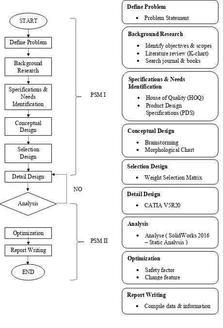
[image:20.595.85.545.68.742.2]
Figure 1.1 : Flowchart NO
Define Problem
Problem Statement
Specifications & Needs Identification
House of Quality (HOQ) Product Design
Specifications (PDS)
Conceptual Design Brainstorming Morphological Chart
Selection Design
Weight Selection Matrix
Optimization Safety factor Change feature Analysis
Analyse ( SolidWorks 2016 – Static Analysis )
Report Writing
Compile data & information Background Research
Identify objectives & scopes Literature review (K-chart) Search journal & books
Detail Design
4 CHAPTER 2
LITERATURE REVIEW
2.1 Brake Disc
Brake discs are brakes that uses force to stop vehicles. Friction force is applied to brake pads of both sides of the brake discs. The discs are normally turns with the wheel of the vehicle and it is overlap with the caliper. Once the brake pedal is pressed, the hydraulic fluid will automatically push the pistons and brake pads to the discs surface. This action will produce friction and tend to halt or slow down the vehicle. The function of the brake pads are to grip the disc until the vehicle slow down or stop (Knight, 2016).
A disc brake consists of rotor, caliper, brake pads and other hardware such as bolts, springs and also clips. Brake disc or brake rotor are normally made up of cast iron where it applies friction to stop or slow the vehicle. Brake rotor can be either solid type where the ventilated rib disc allows air to circulate inside the disc to cool. Brake caliper is a nonrotating part in braking system that is attached to the spindle where it supports the rotor. It comprises of piston, dust boot, caliper housing, piston seal, brake pads and bleeder screw. As for brake pads are thin blocks that clamp the brake rotors to halt or slow down the vehicle. It consists of riveted brake lining that is made of semi metallic friction material or asbestos (Integrated Publishing, n.d.).
2.1.1 Brake Disc Problem
5 2.1.1.1 Warp
Brake discs can be warped when there is a vibration or perhaps judder when braking. The uneven thickness of the brake discs also shows that it is warped (Grant, 2016). Due to Caroll Smith in the article of “The Warped Brake Disc and Other Myths of the Braking System” states that the warped brake discs is mostly friction pad material that is transferred unevenly to the brake discs surface. (Smith, n.d.).
2.1.1.2 Noise
The brake system need to fulfil the customer requirements in term of its noise, durability and performance. Brake disc noise has been a concern especially to the manufacturers of the brake disc systems and the friction materials. Squeal is one of the noise produced by brake disc where it is caused by an increase of coefficient of friction due to the speed decreasing when braking. Besides that, squeal is also caused by the system instability of the structural components of the brake system itself (S. K. Rhee, 1989). The noise produced by brake disc can be categorised into three which are low frequency noise, low frequency squeal and high frequency squeal. The low frequency noise is less than 1000 Hz, low frequency squeal is from 1000 Hz to 5000 Hz while a high frequency squeal is more than 5000 Hz (P., R., & P., 2014).
2.1.1.3 Wear
6 2.1.1.4 Groove
The disc will undergoes wear normally in a form of grooves where brake pads or rivet in contact against it (Ofria, 2016). Groove marks or scoring are deep cuts on the rotor surface where it follows the curve rotation of the rotor. This is due to the worn brake pads exposing the rivet. When the rivet meets the brake disc groove marks will produce either on one side or both side of the brake disc surface. Therefore, skimming process by using brake lathe is required to obtain a smooth surface of brake disc (Disc Brake Service).
2.1.1.5 Corrosion
Brake discs are made up of cast iron where it a material that can corrode easily. Light corrosion can be remove by heavy breaking but braking is lower on light vehicle and may not be enough to remove the corrosion from the brake disc surface (Brake Problems : Wear, corrosion, distortion and other common causes of failure, 2011).
2.2 Brake Lathe (Skimming Machine)
There are two types of brake lathe which are the normal brake lathe and on-car brake lathe. The normal brake lathe is the brake lathe that need the brake disc to be taken to the lathe machine and do the skimming process. Meanwhile, the on-car brake lathe is the machine itself is place to the vehicle to do the skimming machine. It means the skimming process is done without taking out the brake disc from the vehicle (Brake Lathes, 2016).
2.3 Jig
7 2.3.1 Material
Selection of materials are important to resist tear and wear. Materials such as phosphor bronze and other non-ferrous metals including composites and nylons helps in preventing damage to manufacturing part used and reduce wear for certain parts (Okpala & C., The Design and Need for Jigs and Fixtures in Manufacturing, 2015).
2.3.1.1 Gray Cast Iron
Cast irons has been used widely including economical manufacturing processes and it is excellent in friction and wear characterisctics (J.O.Agunsoye, 2014). Majority of industrial automobiles companies manufactured brake disc parts out off gray cast iron. The material is different from the standard steels with more carbon (C) and silicon (Si) (A, 2010). Gray cast iron has a good performance of machining qualities making easily disposed of chips and yielding surface with good wear characteristics (Krause, 1969).
2.3.1.2 Cast Carbon Steel
Most of the steel products starts with castings where it is made from melted iron in electric furnace and recycled steel. Steel is cast into various of sizes and shapes forming from machining, forging or rolling. Besides that, it can be also cast to produce complex components designed from custom moulds (David , Monroe, & Thomas, 2015).
2.3.2 Twin Cutter