ANALYSIS OF DIMENSIONAL ACCURACY AND SURFACE FINISH
PERFORMANCE FOR A 3D PRINTER BASED ON FDM
TECHNIQUE
This report is submitted in accordance with requirement of the University Teknikal Malaysia Melaka (UTeM) for Bachelor Degree of Manufacturing Engineering
(Engineering Design) (Hons.)
by
AMIRAH AFINA BT JOHARI FAISAL STEPHEN B051310201
940326-10-6164
Disahkan oleh:
_____________________________ ______________________________ Alamat Tetap: Cop Rasmi:
_____________________________ _____________________________ _____________________________
Tarikh: _______________________ Tarikh: _______________________
*Jika Laporan PSM ini SULIT atau TERHAD, sila lampirkan surat daripada pihak berkuasa/organisasi berkenaan dengan menyatakan sekali sebab dan tempoh laporan PSM ini perlu dikelaskan sebagai SULIT atau TERHAD.
UNIVERSITI TEKNIKAL MALAYSIA MELAKA
BORANG PENGESAHAN STATUS LAPORAN PROJEK SARJANA MUDA
Tajuk ANALYSIS OF DIMENSIONAL ACCURACY AND SURFACE FINISH
PERFORMANCE FOR A 3D PRINTER BASED ON FDM TECHNIQUE Sesi Pengajian: 2016/2017 Semester 2
Saya AMIRAH AFINA BT JOHARI FAISAL STEPHEN (940326-10-6164) mengaku membenarkan Laporan Projek Sarjana Muda (PSM) ini disimpan di Perpustakaan Universiti Teknikal Malaysia Melaka (UTeM) dengan syarat-syarat kegunaan seperti berikut:
1. Laporan PSM adalah hak milik Universiti Teknikal Malaysia Melaka dan penulis. 2. Perpustakaan Universiti Teknikal Malaysia Melaka dibenarkan membuat salinan
untuk tujuan pengajian sahaja dengan izin penulis.
3. Perpustakaan dibenarkan membuat salinan laporan PSM ini sebagai bahan pertukaran antara institusi pengajian tinggi.
4. *Sila tandakan (√)
(Mengandungi maklumat yang berdarjah keselamatan atau kepentingan Malaysiasebagaimana yang termaktub dalam AKTA RAHSIA RASMI 1972)
(Mengandungi maklumat TERHAD yang telah ditentukan oleh organisasi/ badan di mana penyelidikan dijalankan)
SULIT
TERHAD
DECLARATION
I hereby, declared this report entitled “Analysis of Dimensional Accuracy and Surface Finish Performance for a 3D Printer Based on FDM Technique” is the result of my own
research except as cited in references.
Signature : ………
Author’s Name : AMIRAH AFINA BT JOHARI FAISAL STEPHEN
APPROVAL
This report is submitted to the Faculty of Manufacturing Engineering of Universiti Teknikal Malaysia Melaka as a partial fulfilment of the requirement for Degree of Manufacturing Engineering (Engineering Design) (Hons). The member of the supervisory
committee are as follow:
i
ABSTRAK
ii
ABSTRACT
iii
DEDICATION
I would like to dedicate this work to my Beloved parents
Dearest siblings
Honorable supervisors and lecturers Supportive friends and mates
For giving me moral support, money, cooperation, encouragement and also understandings.
iv
ACKNOWLEDGEMENT
In the name of ALLAH, the most gracious, the most merciful.
All praise to Allah for His mercy I manage to complete this Final Year Project successfully in such smooth and beautiful manner.
I would like to express my deepest gratitude and heartfelt thanks to my supervisor, Dr. Zulkeflee Bin Abdullah for the great mentoring that was given to me throughout the project.
Besides, I would like to thank to other lecturers for the kind supervision, advice and guidance as well as exposing me with meaningful experiences throughout the study.
In addition, I would like to give a special thanks to master student, John who gave me much motivation and cooperation mentally in completing this report.
Finally, I would like to thank everybody who was important to this FYP report, as well as expressing my apology that I could not mention personally each one of you. This accomplishment would not have been possible without all of you. Thank you.
Author,
v
TABLE OF CONTENTS
Abstrak i
Abstract ii
Dedication iii
Acknowledgement iv
Table of Contents v
List of Tables ix
List of Figures x
List of Abbreviations, Symbols and Nomenclatures xii
CHAPTER 1: INTRODUCTION 1 1.1 Background 1
1.2 Problem Statement 2
1.3 Objectives 3
1.4 Scope 3
CHAPTER 2: LITERATURE REVIEW 4 2.1 Additive Manufacturing (AM) 4
2.2 Eight Generic AM Processes 5
2.3 Application of AM 8
2.4 Advantages of AM 11
2.5 Disadvantage of AM 11
2.6 AM and sustainability 13
2.7 Additive Manufacturing System Classification 14
2.7.1 Selective Laser Sintering (SLS) 15
2.7.1.1 Advantages of SLS 17
2.7.1.2 Disadvantages of SLS 17
2.7.1.3 Summary of SLS 17
vi
2.7.2.1 Advantages of FDM 19
2.7.2.2 Disadvantages of FDM 19
2.7.2.3 Summary of FDM 20
2.7.3 3D Printer (3DP) 20
2.7.3.1 Advantages of 3DP 21
2.7.3.2 Disadvantages of 3DP 22
2.7.3.3 Summary of 3DP 22
2.7.4 Stereolithography (SLA) 23
2.7.4.1 Advantages of SLA 23
2.7.4.2 Disadvantages of SLA 24
2.7.4.3 Summary of SLA 24
2.8 Key issues for successful implementation in AM technology 24
2.9 Factors affecting Dimensional Accuracy and Surface Finish 26
2.9.1 Layer thickness 27
2.9.2 Air gap 28
2.9.3 Raster angle 28
2.9.4 Build orientation 29
2.9.5 Road width 29
2.9.6 Number of contours 30
2.9.7 Processing temperature 30
2.9.8 Print speed 30
2.9.9 Tolerance 31
2.9.10 Tessellation 32
2.9.11 Warping/ Shrinkage 34
2.9.12 Under-extrusion 34
2.9.13 Staircase effect 35
2.9.14 Retraction 35
2.10 Three dimensional (3D) printer background; Mojo, UP, Creator Pro 36
vii
CHAPTER 3: METHODOLOGY 37
3.1 Introduction 37
3.2 Flow Chart 39
3.3 Project Implementation Procedure 41
3.3.1 Phase 0: Planning 41
3.3.2 Phase 1: Detail Design 44
3.3.3 Phase 2: Preparation of Specimen 45
3.3.4 Standard Operating Procedure 45
3.3.4.1 Mojo 45
3.3.4.2 UP Plus 2 47
3.3.4.3 FlashForge Creator Pro 49
3.3.4.4 Surface Roughness Tester 50
3.3.4.5 Coordinate Measuring Machine (CMM) 51
3.3.4.6 Vertical Optical Comparator 52 3.3.4.7 Meiji Stereo Microscope 53
3.3.5 Phase 3: Collection of Data 54
3.3.6 Phase 4: Result and Analysis 55
3.4 Summary of Methodology 55
CHAPTER 4: RESULTS AND DISCUSSION 56
4.1 Introduction 56
4.2 Surface Roughness 57
4.2.1 Analysis of data 57
4.3 Dimensional Accuracy 64
4.3.1 Analysis of data 64
4.4 Microscopic inspection 69
4.5 Relationship between Dimensional Accuracy and Surface Roughness 74
4.6 Sustainability Development 76
viii
CHAPTER 5: CONCLUSION AND RECOMMENDATION 78
5.1 Conclusion 78
5.2 Complexity of the project 80
5.3 Long Life Learning 80
5.4 Recommendation 80
REFERENCES 82
APPENDIX A CMM ZEISS Calypso Result 89
APPENDIX B Gantt chart Project 1 91
ix
LIST OF TABLES
2.1 Summary of SLS process 17
2.2 Summary of FDM process 20
2.3 Summary of 3DP process 22
2.4 Summary of SLA process 24
2.5 AM process benchmark part attribute values 25
2.6 Comparison of Mojo, UP Plus 2 and Creator Pro 3D printer 36
3.1 Work piece description for each surface area for surface roughness 43
3.2 Work piece description for each symbol for dimensional accuracy 44
3.3 Standard parameter setting 44
4.1 Mojo, Up Plus and Creator Pro 3D printer result for surface area 1 58 4.2 Mojo, Up Plus and Creator Pro 3D printer result for surface area 2 59 4.3 Mojo, Up Plus and Creator Pro 3D printer result for surface area 3 60 4.4 Mojo, Up Plus and Creator Pro 3D printer result for surface area 4 61 4.5 Mojo, Up Plus and Creator Pro 3D printer result for surface area 5 62 4.6 Mojo, Up Plus and Creator Pro 3D printer result for surface area 6 63 4.7 Summary of the best 3D printer to produce each area of surface roughness 64
4.8 Dimensional accuracy result for Mojo 3D printer 64
4.9 Work piece printing time 66
4.10 Dimensional accuracy result for Up Plus 2 3D printer 67
4.11 Dimensional accuracy result for Creator Pro 3D printer 68
4.12 Summary of the best 3D printer to produce each geometry of dimensional accuracy
x
LIST OF FIGURES
2.1 Wheel illustration the four major aspects in AM 5
2.2 Eight generic AM processes 6
2.3 Steps in AM from design to manufacturing 7
2.4 AM application timeline 8
2.5 Orthoses & Prostheses illustration of fabricated part using traditional and AM 8
2.6 Typical application areas of RP parts 10
2.7 Summary of advantages and disadvantages of AM 12
2.8 Life cycle perspective for identifying sustainability benefits of AM 13
2.9 AM system classification 15
2.10 SLS process illustration 16
2.11 (a) Layer by layer manufacturing (b) Generic fixturing 16
2.12 FDM process illustration 18
2.13 3DP process illustration 21
2.14 SLA process illustration 23
2.15 Graph Accuracy vs. Surface Roughness 26
2.16 Factors contribution that affects the quality of prototypes in AM 27
2.17 (a) Layer thickness 27
(b)Sliced view of the model using virtual AM simulation software 27
2.18 FDM tool path parameters 28
2.19 Build orientations 29
2.20 Effect of too high print head, jerking 31
2.21 Tessellation of the surface of a spherical shape 32
2.22 Slicing of a ball 33
2.23 Different tessellation algorithms in work CAD system 33
2.24 Illustration of inaccuracy printer bottom layer 34
xi
3.1 Benchmarking of CAD model with referenced feature identification (IDs) 38
3.2 Flow of the project 39
3.3 Detail design of the product with dimensions 42
3.4 Work piece area for surface roughness measurement 43 3.5 Work piece symbol for dimensional accuracy measurement 43 3.6 Mojo 3D printer 46
3.7 Mojo parameter set up before printing started 46
3.8 Work piece immersed in ultrasonic tank 47
3.9 UP Plus 2 3D printer 47
3.10 Up Plus 2 setting preference 48
3.11 Print platform cleaning 48 3.12 FlashForge Creator Pro 3D Printer 49
3.13 Parameter setting of the Creator Pro printing 49
3.14 Surface roughness tester 50
3.15 Zeiss Contura G2 CMM 51
3.16 Work piece measured by CMM 52
3.17 Vertical Optical Comparator 53
3.18 Meiji Stereo Microscope 54
4.1 Surface area 2 measured by surface roughness tester 60
4.2 Work piece built by Mojo 3D printer 65
4.3 Tessellation slicing (a) Solidworks 2013 software (b) Catia V5R19 software 66
4.4 Macroscopic images for Mojo 3D Printer work pieces 69
4.5 Macroscopic images for Up Plus 2 3D Printer work pieces 70 4.6 Macroscopic images for Creator Pro 3D Printer work pieces 71
4.7 Staircase Effect 72
4.8 Warping at the one side only 73
4.9 Poor build plate adhesion 73
xii
LIST OF ABBREVIATIONS, SYMBOLS AND
NOMENCLATURE
ABS - Acrylonitrile Butadiene Styrene
AM - Additive Manufacturing
AMC - Advanced Manufacturing Center
AFOs - Ankle Foot Orthoses
CAD - Computer-aided design
CMM - Coordinate Measuring Machine
CNC - Computer Numerical Control
EBM - Electron Beam Melting
FDM - Fused Deposition Modeling
FKP - Fakulti Kejuruteraan Pembuatan
FOs - Foot Orthoses
LOM - Laminated Object Manufacturing O&P - Orthoses and Porthoses
PLA - Polylactic Acid
Ra - Roughness Average
RP - Rapid Prototyping
SLA - SLA
SLS - Selective Laser Sintering
SOP - Standard of Procedure
STL - STereoLithography
UTeM - Universiti Teknikal Malaysia Melaka
1
CHAPTER 1
INTRODUCTION
Chapter 1 provides a brief explanation about this project, the background of the project title, “Analysis of dimensional accuracy and surface finish performance for a 3D printer based on FDM technique” and will discuss the problem statement, objectives and scope of the project.
Background
Masood et al., (2016) pointed out that Fused Deposition Modeling (FDM) is an Additive
2
The main purpose of this project is to analyze the dimensional accuracy and surface finish performance for a 3D printer based on FDM technique. Since there are various 3D printer machines in UTeM, especially in Main Campus, experiments will be conducted using three types of machines which are Mojo, UP Plus 2 and Creator Pro located at Rapid Prototyping Laboratory. All of these machines are from beginner to intermediate level but have different specifications, pros and cons (3D Hubs, 2016). Each work piece produced have been drawn by two different types of CAD software which are Solidworks 2013 and Catia V5R19. The 3D printer will be ranked according to the part or product quality produced based on their dimensional accuracy and surface roughness.
Problem Statement
Boschetto & Bottini (2016) pointed out that, FDM is the technology of additive manufacturing that is capable to create model, tooling and functional parts without geometrical complexity restrictions. In spite of the possible favorable aspects of this innovation, obtaining a precise accuracy is hard to achieve. This includes poor surface quality. Islam et al., (2013) have mentioned that 3D printed work piece commonly have
dimensional accuracy and surface finish problems. Besides, parts produced by different 3D printers have varied accuracy and surface finish. The parts that not meet the design specifications according to the standard will affect the performance and the assembly fit with other components. All 3D printer machines have their own specifications and some of them do not provide consistent and precise measurement of the product being produced. By using three types of different FDM machines, the work piece produced from each machine will be compared through their dimensional accuracy and surface finish.
3 Objectives
The objectives of this study are as follows:
i. To study and utilize three models of FDM 3D printer; Mojo, UP Plus 2 and Creator Pro.
ii. To compare the dimensional accuracy and surface finish of three models FDM 3D printer work piece.
iii. To investigate the relationship of dimensional accuracy and surface finish between 3D printers.
Scope
The scope of this project focuses on the analysis regarding dimensional accuracy and surface finish performance for a 3D printer based on FDM technique. The sample of a model is drawn using Solidworks 2013 and Catia V5R19 software according to the benchmark evaluation from Johnson et al., (2011). All work pieces drawn will be converted into STL
4
CHAPTER 2
LITERATURE REVIEW
This chapter discusses about the related knowledge of the project which cover the introduction of the Additive Manufacturing, Fused Deposition Modeling, dimensional accuracy and surface roughness.
Additive Manufacturing
Technologies, Medium, & Powell (2008) mentioned in worldwide competition, most of the companies are seeking for the new technologies to improve their business processes and speed up the product development cycle due to the demands for cost savings. One of the key enabling technologies with its competence to minimize the product design and development time involves using the technology of Rapid prototyping (RP) also known as Additive Manufacturing (AM).
AM is an innovation for rapidly fabricating physical models, functional prototypes and limited batches of parts directly from Computer Aided Design (CAD) data. Besides, AM also refers to the three-dimensional (3D) printing, build techniques layer-by-layer, material addition manufacturing, and solid free-form fabrication. AM shortens the time-to-market of products and enlarges technology competitiveness.
Guan et al., (2015) also stated that AM is now experiencing an advanced application in
5
[image:21.595.179.435.195.455.2]Barner (2015) also added in most cases layer by layer following a build-up code, objects with hollow spaces, undercuts or complete assemblies are feasible because AM is straightly derived from a three-dimensional model, similar to modern CNC manufacturing. The only difference is that materials are not removed, but rather plotted and no tool is required.
Figure 2.1: Wheel illustration the four major aspects in AM (Chua et al., 2010).
Figure 2.1 shows the four major aspects in AM which are the methods, applications, material and input.
Eight Generic AM Processes
6
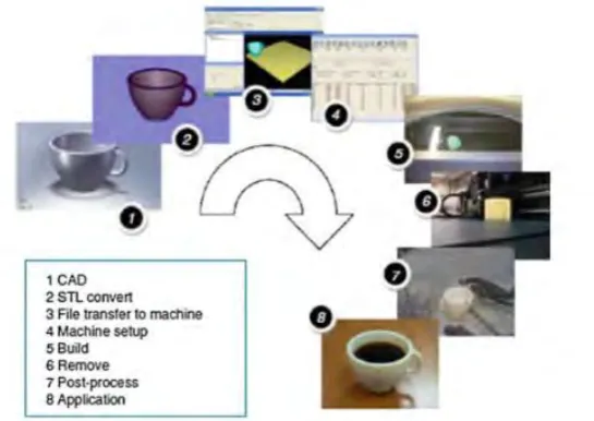
Figure 2.2: Eight Generic AM Processes (Gibson, Rosen, & Stucker, 2010).
1st Step: CAD
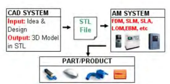
First step of the AM process must begin from a product modelcreated using any CAD solid modeling software or reverse engineering equipment using laser scanning equipment (Gibson et al., 2010).
2nd Step: Conversion to STL
The second step is to convert the CAD data into the STL file. Almost every AM machine recognize the STL file that has turned into an accepted standard. They are sliced into thin cross-sectional layers (Gibson et al., 2010).
3rd Step: Transfer to AM machine and STL File Manipulation
Once the STL file has been created, it can be sent directly to the AM machine to build the part straight away. In some cases, there will be a few adjustments and actions required prior to building the part (Gibson et al., 2010).
4th Step: Machine Setup
7 5th Step: Fabrication of the part
The AM machine should be monitored although the fabrication of the part is an automated process to avoid power failure or running out of materials throughout the FDM process (Gibson et al., 2010).
6th Step: Removal of Part
The part should be removed once the FDM procedure is finished. A portion of the part created can be removed with the guide of devices. This often involves manually removing the part from the machine, cleaning off the support structure and removing the excess material which requires much time and skill (Gibson et al., 2010).
7th Step: Post processing
After the part is removed, they may require some completing of the parts before they are prepared to be utilized. Cleaning, sandpapering, paintings and coatings are done to give a good surface finish (Gibson et al., 2010).
8th Step: Applications
[image:23.595.167.443.516.653.2]Although parts may be made from similar material with conventional manufacturing, some parts may fail under mechanical stress due to small voids or bubble trapped while being built (Gibson et al., 2010).
Figure 2.3 Steps in AM from design to manufacturing (Moroni, Syam, & Petró, 2014).
8 Application of AM
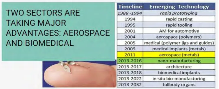
[image:24.595.120.492.195.347.2]AM has developed rapidly and its application has extended from prototyping to conceivable end-use items. This can be demonstrated in Figure 2.4.
Figure 2.4 AM application timeline (Royal Academy of Engineering, 2013).
Figure 2.4 shows the application timeline of AM. It has begun from 1988 and looking forward on their future potential until 2032.
Medical, aerospace and automotive applications in AM are explained below.
[image:24.595.175.433.552.684.2]a) Medical application