a novel 3D in vitro testing model
.
White Rose Research Online URL for this paper:
http://eprints.whiterose.ac.uk/131347/
Version: Published Version
Article:
Behbehani, M., Glen, A., Taylor, C.S. et al. (3 more authors) (2018) Pre-clinical evaluation
of advanced nerve guide conduits using a novel 3D in vitro testing model. International
Journal of Bioprinting, 4 (1).
10.18063/IJB.v4i1.123
[email protected] https://eprints.whiterose.ac.uk/ Reuse
This article is distributed under the terms of the Creative Commons Attribution (CC BY) licence. This licence allows you to distribute, remix, tweak, and build upon the work, even commercially, as long as you credit the authors for the original work. More information and the full terms of the licence here:
https://creativecommons.org/licenses/
Takedown
If you consider content in White Rose Research Online to be in breach of UK law, please notify us by
3D printing for drug manufacturing: A perspective on the future of pharmaceuticals. © 2018 Mehri Behbehani,et al. This is an Open Access article distributed under the terms of the Creative Commons Attribution 4.0 International License (https://creativecommons.org/licenses/by/4.0/),
Pre-clinical evaluation of advanced nerve guide
conduits using a novel 3D
in vitro
testing model
Mehri Behbehani
1, Adam Glen
1, Caroline S. Taylor
1, Alexander Schuhmacher
2, Frederik
Claeyssens
1, John W. Haycock
11Department of Materials Science and Engineering, The University of Sheffield, UK
2Faculty of Applied Chemistry, Reutlingen University, Germany
Abstract: Autografts are the current gold standard for large peripheral nerve defects in clinics despite the frequently occurring side effects like donor site morbidity. Hollow nerve guidance conduits (NGC) are proposed alternatives to autografts, but failed to bridge gaps exceeding 3 cm in humans. Internal NGC guidance cues like microfibres are believed to enhance hollow NGCs by giving additional physical support for directed regeneration of Schwann cells
and axons. In this study, we report a new 3Din vitro model that allows the evaluation of different intraluminal fibre
scaffolds inside a complete NGC. The performance of electrospun polycaprolactone (PCL) microfibres inside 5 mm
long polyethylene glycol (PEG) conduits were investigated in neuronal cell and dorsal root ganglion (DRG) culturesin
vitro. Z-stack confocal microscopy revealed the aligned orientation of neuronal cells along the fibres throughout the whole NGC length and depth. The number of living cells in the centre of the scaffold was not significantly different to
the tissue culture plastic (TCP) control. Forex vivoanalysis, DRGs were placed on top of fibre-filled NGCs to simulate
the proximal nerve stump. In 21 days of culture, Schwann cells and axons infiltrated the conduits along the microfibres
with 2.2 ± 0.37 mm and 2.1 ± 0.33 mm, respectively. We conclude that thisin vitromodel can help define internal NGC
scaffolds in the future by comparing different fibre materials, composites and dimensions in one setup prior to animal testing.
Keywords: 3D model; intraluminal scaffold; peripheral nerve; regenerative medicine; microfibres
*Correspondence to: John W Haycock, Department of Materials Science and Engineering, Sir Robert Hadfield Building, Mappin Street, S1 3JD, UK; [email protected]
Received:September 29, 2017;Accepted:November 22, 2017;Published Online:December 20, 2017
Citation:Haycock J W, 2018,Pre-clinical evaluation of advanced nerve guide conduits using a novel 3D in vitrotesting model. Int JBioprint,4(1): 123. http://dx.doi.org/10.18063/IJB.v4i1.123.
1. Introduction
Injuries to peripheral nerves can affect the general public in all age groups, mostly caused by domestic, industrial or traffic accidents. Severe transection injuries are often life-changing and may result in defects of motor and sensory function. These injuries can often be repaired through a self-regeneration mechanism after Wallerian degeneration takes place[1].
However, a major concern is the increasing risk of incomplete functional and motor recovery with increasing degree of injury[2]. Current clinical treatments
motor nerve lesions with commonly used sensory sural nerve grafts[3-5].
In recent years, bioengineers have focused on the development of NGCs to provide an alternative treatment to autografts, where different materials and designs were explored resulting in a number of devices that have seen FDA approval (Neuroflex/ Neuromatrix®, NeuraGen®, AxoGuard®, Avance®,
Neu-rolac® or SaluTunnel®). However, these
commercial NGCs lack internal guidance structures and cannot exceed injury gaps greater than 3 cm, which is shorter than the defined critical nerve gap of 4 cm in humans[6,7]. To this date, no other commercial
solution has been presented. Therefore, key challenges now focus on enhancement of NGCs by including internal conduit guidance structures for targeted axon regeneration through the nerve gap to maximise the number of regenerating axons and therefore the regeneration outcome. Aligned fibres of a natural or synthetic material can be one approach to improve hollow nerve guides[8-11] by mimicking the natural
regeneration guidance cues of bands of Büngner, where Schwann cells and fibroblasts form aligned bands between the proximal and distal nerve end to guide axons to their target effectors[12]. With adjustment of the fibre
density in the NGC lumen, specific regeneration needs can be addressed like varying axon numbers in nerves. In comparison, hollow nerve guides only provide outer guidance for the injured nerve to keep both nerve stumps connected but cannot provide relevant internal guidance support for regenerating cells and tissue. Furthermore, fibre containing conduits would not require an adaption of nerve fascicles and blood vessels between the proximal stump and the conduit which is necessary when using autografts[13].
Newly developed NGC scaffold designs, which have seen in vivo implantation, have compared favourably to hollow conduits and autografts[8,14-16].
However, new designs have, for the most part, not been directly compared to previous generation NGCs, or to currently used nerve conduits. Furthermore, with advanced NGC improvements more adequate evaluation techniques are required. More complex NGC structures, such as those that comprise of two components, like an additional internal scaffold, would greatly benefit from novel assessment techniques like in
vitro evaluations in three dimensions, instead of
relying on data retrieved fromin vitroanalysis on flat material films. We therefore hypothesized that the evaluation of intraluminal nerve guide scaffolds (e.g.
microfibres) can be directly conducted in whole nerve conduits in order to provide a prospective platform for comparison of different internal NGC scaffolds. The effectiveness of the model was determined by neuronal cell culture and primary rat dorsal root ganglion explants in conjunction with cellular responses investigated using three-dimensional z-stack confocal and two-photon imaging.
2. Methods
2.1 Conduit Fabrication
Three-dimensional conduits were fabricated by microstereolithography. Polyethylene glycoldiacrylate (Mn = 575 g/mol, Sigma, Poole, U.K.) was mixed with 4% diphenyl-(2,4,6-trimethylbenzoyl)-Phosphineoxide/2 -hydroxy-2-methylpropiophenone 50/50 photoinitiator (wt/wt, Sigma) to obtain a photocurable version of the target polymer. A cross sectional image of the required conduit size (1.2 mm internal diameter, 250 µm wall thickness) was uploaded to a digital micromirror device (Texas Instruments Incorporated, USA, associated software: ALP-3 Basic, ViALUX GmbH), which comprised of a range of mirrors, where each 20 µm size mirror represented a 1:1 object-to-image size ratio. The beam of a 10 mW 405 nm laser (Vortran Laser Technology Inc, USA) was expanded and aligned while running through a spatial filter and a mirror set. The beam then reached the digital micromirror device and was reflected in the shape of the uploaded cross section image. The liquid prepolymer was placed under a motorized z-axis translation stage (Thorlabs Ltd, UK, associated software: APT software), which was mounted at the liquid-air interface. Controlled by velocity and acceleration, the z-stage moved down into the bulk material where the irradiated regions were polymerized. Once the final length of the structure was reached, the laser power was turned off and the stage returned to its origin, carrying the complete 3D conduit structure. Unreacted prepolymer was washed off with isopropyl alcohol (IPA, Fisher Scientific UK). All fabricated structures were washed in IPA for 7 days to ensure full removal of unreacted prepolymer and added photoinitiator.
2.2 Microfibre Fabrication
was connected to a high voltage supply (Genvolt UK) and the polymer-loaded syringe placed in the mount of a programmable syringe pump (WPI Europe) and constantly pumped through with a flow rate of 4 ml/hr. Polymer jet formation was achieved by a voltage of 15 kV. The formed fibres were collected on an earthed rotating aluminium collector (IKA Works) wrapped in aluminium foil with a rotation speed of 2000 rpm.
2.3 Characterisation of Microfibres
Gold coated electrospun fibre samples were imaged using a XL-20 scanning electron microscope (SEM, Koninklijke Philips N.V.) operating at 15 kV. On each aluminium fibre sheet, three parallel arranged squares were analysed regarding fibre diameter and density. The fibre diameter was analysed using a ruler tool in the SEM related XL software. The amount of fibres per 50 µm were counted and averaged over all images.
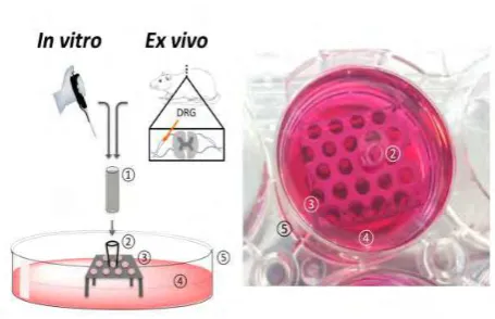
2.4 Combination of Conduit and Microfibers Approximately 6000–7000 PCL microfibres were threaded per PEG conduit. The fibre sheets were cut to the required width and 1–2 cm of the fibres were manually lifted off in the direction of the fibre alignment. These fibres were twisted between the fingers, where the twisted end was used in a similar manner to a needle. PEG NGCs were threaded onto PCL fibres (non-bunched end) like pearls on a chain and fibre excess was cut with scissors. A schematic of the workflow can be found inFigure 1.
2.5 Cell Culture in Whole Nerve Guides
NG108–15 neuroblastoma × glioma rat/mouse hybrid neuronal cells (Public Health England, UK) were cultured in whole nerve guides with a cell concentration of 6 × 10⁵ cells in proliferation medium, containing of
Dulbecco’s Modified Eagle Medium (DMEM, Sigma), 10% foetal bovine serum (FBS, v/v, Biosera), 0.25 mg/mL amphotericin (Sigma), 200 mM L-glutamine (Sigma), 100 units/mL penicillin and 100 mg/mL streptomycin (Sigma) for 4 days. Cells were seeded with 15 µL of cell suspension by directly pipetting on top of the fibres in the conduits. The NGCs were transferred to the designed culturing setup in a 6-well plate and cells were allowed to attach at 37 °C for 30 minutes before wells were filled with proliferation medium. Neuronal NG108–15 cells were used between passage 14–20 and
cultured at 37 °C in a humidified 95% air and 5% CO2
[image:4.595.310.539.111.302.2]atmosphere.
Figure 1.(A) Schematic workflow of the production of PCL microfibres using electrospinning, following the procedures of Daudet al.[18], the analysis and threading procedure of microfibres
and the fabrication of PEG conduits by microstereolithography, following the procedures of Pateman et al.[17] SEM
micrographs illustrating components of the nerve guide testing device; (B) A 5 mm long hollow PEG NGC, fabricated by microstereolithography, and (C) PCL microfibres spun by electrospinning. (D) Conduit and microfibres were combined into a final testing nerve guide device.
2.6 F-actin Labelling of Neuronal Cells
in the staining solution for 60 min at 37 °C. Confocal imaging was conducted in PBS immediately after staining (details below).
2.8 Dorsal Root Ganglion Isolation and Culture Male Wistar rats aged 10–12 weeks were sacrificed by cervical dislocation (schedule I procedure, UK Home Office). Rats were skinned and the spine was removed. DRGs were extracted after the spine was cut open, dorsal side facing up, and the spinal cord and meninges were removed. The nerve roots of each DRG were trimmed and explant DRG bodies placed on top of the nerve guides (one DRG body per conduit), which were held in place by the described setup. DRGs were incubated at 37 °C for 15 min to allow attachment. Afterwards, samples were fully covered with proliferation medium and incubated at 37 °C in a humidified 95% air and 5% CO2atmosphere
for 21 days.
2.9 III-tubulin and S100 Labelling of Dorsal Root Ganglia
In order to reveal neuron-specific protein III-tubulin and Schwann cell-specific protein S100 im-munolabelling was conducted. After fixation with 3.7% PFA for 3 h and permeabilising cell membranes with 0.1% Tween X-100 for 1 h, protein binding sites were blocked with 3% bovine serum albumin (BSA, w/v in PBS, Fluka) for 30 min and subsequently washed with PBS. Anti- III-tubulin primary mouse antibody (1:200 in 1% v/v BSA, Promega, G7121) and anti S100 primary rabbit antibody (1:600 in 1% v/v BSA, Abcam, Ab868) were added to the samples for 48 h at 4 °C, followed by three washes in PBS. The secondary antibodies, horse anti-mouse lgG conjugated to Texas Red (1:1000 in 1% BSA; Vector Laboratories, TI-200) and goat anti-rabbit lgG conjugated to fluorescein isothiocyanate (FITC) (1:1000 in 1% BSA; Vector Laboratories, F1-1000) were added to the samples and incubated for 120 min at room temperature. Before imaging, samples were washed, then resubmerged in PBS.
2.10 Confocal and 2-photon Laser Microscopy For imaging samples, a Zeiss LSM 510 META confocal microscope (Carl Zeiss Ltd, UK) with a 543 nm and a 488 nm laser was used. DAPI stained samples were imaged using an additional 2-photon 780 nm laser (Chameleon Ultra III, Coherent Inc, USA). Samples were arranged in a 6-well plate or were fixed
[image:5.595.310.538.236.383.2]on a glass microscope slide and imaged in PBS using a 10× magnification ZeissW Plan Achromat water-dipping objective lens. For imaging FITC- and SYTO 9-labelled samples incident and excitation wavelengths of ex = 488 nm/ em = 525 nm were used, and wavelengths of ex = 543 nm/ em = 576 nm to image Texas Red, TRITC and propidium iodide-labelled samples. Cell nuclei were visualized at ex = 780 nm/ em = 480 nm. Images were stitched together and analysed using Zeiss LSM Image Browser software and Image J 1.49 (National Institute of Health, USA).
Figure 2.(Left) Schematic of the designed 3D model setup to evaluate the internal nerve guide scaffoldsin vitroandex vivo. (Right) Photograph of the experimental setup. Cell cultivation was conducted directly inside the incorporated scaffolds. Forex vivo analysis, dorsal root ganglia (DRGs), isolated from rat spines, were placed on top of the scaffolds. The test NGC device (1) was fitted with an adapter. (2) To a perforated metal plate. (3) And secured in a well of a commercial 6-well plate (5). In order to perform cell culture experiments, wells were filled with culture medium. (4) Until NGCs were covered.
2.11 Statistics
Data are shown as mean ± SD of three independent experiments, where each experiment has been conducted in triplicate, except for the analysis of microfibres using DRGs, where each experiment had a sample size of four. Statistical differences were tested by ordinary one-way ANOVA Tukey’s multiple comparisons test and differences were considered significant whenp≤ 0.05.
3. Results
supported the culturing of primary and non-primary neuronal and Schwann cells by following standard cell culture protocols in a more complex, multilayered environment represented by the conduit scaffold architecture under investigation
3.1 Design of theIn VitroTesting Setup and Example Device
The developed 3D model used a PEG nerve guide conduit filled with PCL microfibres, based on the procedures developed by Patemanet al.,[17]and Daud
et al.[18].Figure 1Ashows a detailed schematic of the
production of PEG conduits with an internal PCL microfibre scaffold. PEG conduits, fabricated by microstereolithography, measured 5 mm in length and had an internal diameter of 1.2 mm with a wall thickness of 250 µm (Figure 1B). The internal lumen diameter was designed to fit a rat dorsal root ganglion
for ex vivo conduit testing. PCL was electrospun to
aligned fibres (Figure 1C), which had an average fibre diameter of 5 ± 0.2 µm. The example device was fabricated by combining the above to a PEG NGC with an internal aligned fibre scaffold to investigate cell’s behaviour in response to the introduced internal guide in a ready-to-implant device (Figure 1D). PCL microfibres inside example PEG conduits were tested using a developed testing setup that comprised of two components, a stainless steel perforated metal plate and a polystyrene adapter to match conduit size and the metal stage (Figure 2). Metal stages and polystyrene adapters were sterilised by autoclaving and 70% ethanol treatment respectively. The setup was compatible to a standard 6-well plate and could be used to investigate different conduit sizes, where conduit length analysis was only limited by the well height.
3.2 Cell Orientation Analysis in the 3D Nerve Guide Architecture
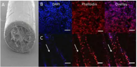
In order to successfully analyse the behaviour of neuronal cells on internal NGC scaffolds, key questions of cell attachment and distribution on the scaffolds needs to be answered. Neuronal NG108-15 cells were cultured for 4 days and their morphology investigated by revealing cell nuclei and cytoskeleton with DAPI and F-actin-binding phalloidin. Figure 3A
shows an SEM image of the experimental NGC device comprising PCL microfibres inside the lumen of a tubular PEG conduit. Neuronal cells were seeded on internal fibre scaffolds in whole NGCs using the described setup (Figure 2) and followed standard cell
[image:6.595.308.539.191.304.2]seeding procedures by directly applying the cell suspension on the nerve guide scaffold without the need of a pump perfusion system for the supply of medium. As shown in Figures 3B and 3C, neuronal cell orientation on the internal fibre scaffold was compared to cells on TCP. In monolayer, cells are randomly arranged and evenly attached to the TCP substrate (Figure 3B).
Figure 3. Confocal microscopy images of neuronal cells in nerve guides filled with PCL microfibres. (A) Neuronal NG108–15 cells were cultured in 5 mm long PEG NGCs with an internal aligned PCL microfibre scaffold in proliferation medium for 4 days. Neurons were labelled with F-actin-binding phalloidin-TRITC (red) and DAPI (blue) to reveal cytoskeletons and nuclei respectively. (B) TCP was used as a flat substrate control, on which neurons were randomly orientated. (C) Neurons cultured in whole NGCs orientated with the PCL fibre alignment inside whole PEG nerve guides. Arrows indicate the direction of microfibres in the NGCs. Scale bars = 20 µm.
In Figure 3C, it is clearly demonstrated how
(illustrated by single images) and along the whole tube (illustrated by images taken on three different positions) (Figure 4B). Together, these results provide insight into neuronal attachment, alignment and distribution on PCL microfibres incorporated into NGCs when using the developed culture model, where neurons orientated like they would do as bands of Büngner in peripheral nerve regenerationin vivo.
Figure 4. 3D confocal microscopy images of neuronal cell distribution on aligned PCL fibres in whole nerve guides. The incidence of neuronal NG108–15 cells were evaluated on three different positions throughout the NGC and neurons revealed by phalloidin- TRITC and DAPI. For confocal microscopy, the fibres were taken out of the tube and mounted on a glass microscope slide. (A) Graphical representation of an NGC with incorporated aligned fibres. The arrow indicates the position where cells were seeded in the tubes. Imaging was conducted in three different positions on the fibres (illustrated by numbers). (B) 3D z-projection confocal images of neuronal cell distribution on microfibres inside NGCs. Z-stack images (depth: 400 µm) were taken at three different positions as illustrated in A. Arrow indicates the direction of microfibres in the NGCs
3.3 Cell Survival Inside Microfibre-filled NGCs Cell viability not only plays an important role for the
in vitro analysis and evaluation of cell behaviour and
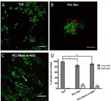
properties but is also crucial in the injury site to maintain as many viable cells as possible to increase effectiveness of tissue regeneration. In the described model, neuronal cells were seeded with greater numbers per area than on flat monolayer substrates and were surrounded by the conduit walls structurally mimicking a peripheral nerve whereas in contrast, monolayer cultured cells are exposed to an open system with unrestricted medium supply. Based on these culturing differences, a comparative overview staining of live and dead neuronal cells was conducted between cells on monolayer TCP substrates or PCL respectively, and cells, which were cultured on PCL microfibre scaffolds inside NGCs (Figure 5A–C).
[image:7.595.308.538.195.404.2]Neuronal cells attached and expanded in different patterns on the three different substrates. On TCP, neurons distributed evenly over the entire monolayer substrate (Figure 5A), where cells on PCL films showed a clumped arrangement (Figure 5B). Neurons cultured on microfibres inside the NGC device formed aligned cellular bands in the direction of the fibres (Figure 5C).
Figure 5. Overview of live and dead neuronal cells in the proposed 3D model. NG108–15 neuronal cells were cultured on TCP (A), PCL films (B) and on PCL microfibres inside the NGC test device (C) for 4 days. Live cells were identified with Syto 9 (green) and dead cells with propidium iodide (red). Cell imaging on fibres was conducted in the centre of the scaffold in z-stacks (depth 400 µm) and was illustrated as maximum intensity images. Arrow indicates the fibre orientation in NGCs. (D) shows the percentile distribution of living (dark bars) and dead cells (light bars) in the three different conditions (A–C). Living cells on TCP accounted 98.9 ± 0.6 %, on PCL films 85.6 ± 3.9 % and 91 ± 4.6 % on microfibres in NGCs in relation to the total cell population. No significant (ns) differences between data points of living cells on TCP and microfibres inside NGCs could be found, where significance was seen between TCP and PCL films. Data points of living cells were analysed by one-way ANOVA (**p < 0.01). Scale bar = 150 µm."
neuronal cells was observed between PCL films and TCP. Taken together, microfibres supported the alignment of neuronal cells, yielded in living cell numbers greater than 90% and yielded in higher numbers of living cells compared to the flat PCL control.
3.4Ex vivodorsal root ganglion culture
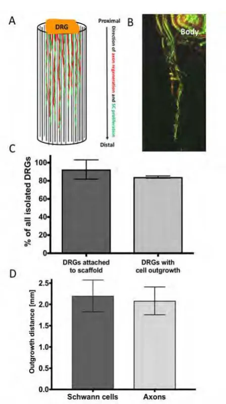
[image:8.595.314.538.74.474.2]Schwann cell proliferation and migration from the proximal to the distal nerve stump is one major key event in peripheral nerve regeneration to provide guidance for re-growing axons in order to successfully reinnervate target effectors on distal site. Simulating the proximal injury site in vitro, a rat dorsal root ganglion was placed on top of the example NGC device for investigations on internal scaffold performance by analysing Schwann cell proliferation and axon outgrowth along the microfibre scaffold from the explant towards the tube end (illustrated in Figure 6A). Dorsal root ganglia have been chosen as they accommodate sensory neuronal cell bodies, Schwann cells and fibroblastic cells, and represent a morein vivo like environment with primary cells in a co-culture arrangement. In order to analyse the success of the dissection procedure and the ability of microfibres to support DRG outgrowth, DRGs survival and attachment to the NGC device were analysed. The number of attached DRGs to the conduit scaffolds was determined visually and was normalised to the total number of isolated DRGs. In addition, the number of DRGs were counted, where microfibres supported the outgrowth of cells from the DRG body and numbers expressed in relation to all dissected DRGs. More than 90% of all isolated DRGs from male Wistar rats, in the age of 10–12 weeks, attached to the nerve guides using the described setup where more than 80% of the explants showed positive labelling for S100 and III tubulin away from the ganglion body (Figure 6C). In order to analyse the cell outgrowth distance from the DRG body towards the tube end, the incorporated PCL microfibre scaffold was removed from the conduit after 21 days of culture and Schwann cells labelled for S100 (green fluorescent signal) and axons for III tubulin (red fluorescent signal) (Figure 6B).
Green fluorescence from axons III tubulin could be seen simultaneously where Schwann cells were located. The co-localization could be identified by an overlay of green and red fluorescent signals appearing in a yellow-orange colour (Figure 6B). The distance that neuronal and Schwann cells infiltrated into the conduit was defined as the last detectable signal seen distant from the DRG body. The distance of outgrown cells was of particular importance as demonstrating the microfibres efficiency to support cell infiltration in a simulated nerve lesion in vitro. Schwann cells migrated and proliferated 2.2 ± 0.37 mm along the aligned microfibre scaffold inside the NGCs, where neuronal cells showed the extension of axons by 2.1 ± 0.33 mm (Figure 6D). Together, Schwann cells and axons infiltrated 43 % of the 5 mm long conduitin vitroin 21 days.
4. Discussion
Most cell-based research is acquired via experiments in monolayer cultures and largely assumes that these monolayer cultures reflect the physiology of tissue. To this day, cell cultivation in a monolayer is the traditional way of culturing cells. Cultivation in monolayers has proved to be simple, convenient and lead to relatively fast results. However, for some time,
onlyin vitro2D cultivation models andin vivoanimal
models were available and used for early stage medical device evaluation[19–21]. Between both models
there is a large gap in relation to the physiological relevance. Monolayer cultures are far away from the biological behaviour in the human body, especially when cell lines were chosen over primary cells, and animal studies, whilst representing a whole organism and metabolism, are not human. Though animal studies can mirror human biological responses, they do not always reproduce human physiology[22].
Especially the dominant use of rat sciatic nerve injury models to study NGCs, which have limitations when translating results to humans[23]. Rats are too small in
size to enable the study of human critical nerve gap lengths of > 4 cm and homogenous in-bred strains reduce the variability between results. Another concern that may result in mistranslation is the attempt to compare experiments of healthy animals versus sick patients, who normally suffer from multiple injuries besides the injury to a peripheral nerve due to traffic, industrial or domestic accidents.
Additionally, there is a regulatory and ethically driven effort to reduce the number of animals used in medical research.
3Din vitromodels are of increasing interest because
of their “closer-to-in-vivo” behaviour with higher physiological relevance. In 3D models, cells can be cultivated in three dimensions like in their natural environment in tissues and organs. In neurosciences, 3D models are mostly devoted to the central nervous system to study the neuronal network and signalling pathways, brain barriers, disorders and the effects of neurotoxins (reviewed by[24,25]). Studies on peripheral
nerve injuries, and nerve guides in particular, would benefit from in vitro 3D models due to the discussed limitations of animal injury models, 2D in
vitro cultures and the lack of published data. Today
there is an increased need for 3D models on internal NGC scaffolds. In particular, hollow NGCs have shown their limitations in repairing nerve gaps exceeding 3 cm and improvement on this matter is urgently needed. Different attempts have been made to study internal scaffolds for NGCs in a three-dimensional environment but documentation on a 3D in vitro
model to test different scaffolds in one setup prior to animal implantation is still missing. In support of this notion, we developed an in vitro3D DRG model that allows the investigation of different internal fibre scaffolds inside an NGC. In order to ensure that the microfibre scaffold supported cell growth and viability throughout the entire conduit length and depth, cell culture was conducted prior to DRG cultures. The developed system showed anin vitro3D environment, which was based on the final implantable product and therefore more likely mimicked physiological relevant conditions. The morphology and viability of neuronal cells on microfibres inside a tubular nerve guide using the proposed setup was examined, where neuronal morphology remained unchanged throughout the entire nerve guide and where cells showed similar and not significantly different viability rates compared to the flat TCP control. This is of particular interest as it was previously mentioned that even thin 3D scaffolds showed a much lower cell growth in the centre of those structures due to the lack of nutrient and oxygen diffusion to the scaffold core[26–29]. Herein, the number
of living cells inside the centre of the microfibre scaffold measured more than 90%.
multi-cell type source and their anatomical morphology is suitable to simulate the proximal nerve stump after nerve injury when placed on top of an NGC. Additionally, DRGs contain three main cell types: sensory neurons, which are surrounded by satellite glial cells, Schwann cells and fibroblasts, which are arranged in a collagen-dominant extracellular matrix[30].
Evaluating NGC scaffolds using DRGs therefore allows axon-glia communication, approximates the native peripheral nerve environment and contains the major cell components, which take part in peripheral nerve regeneration. During Wallerian degeneration, Schwann cells and fibroblasts proliferate and migrate from both the proximal and the distal nerve stump into the nerve lesion and provide a chemical and physical guide for regenerating axons[1,31]. The close association of
Schwann cells and axons was also observed in this study (yellow fluorescent signal in Figure 6B). In addition, Schwann cells proliferated further than the axons regenerated (Figure 6D), suggesting Schwann cells direct extending axons. The use of DRGs as an evaluation tool for peripheral nerve repair studies is not a new idea and was presented by several research groups in the past[18,32–34]. However, the described in
vitro assessment methods are mainly confined to the
evaluation of a single internal NGC scaffold. The current study suggests using DRGs to evaluate multiple scaffold structures inside the NGC, where the model is not restricted to the evaluation of a single conduit design. Additionally, this study showed the use of DRGs to simulate the proximal nerve stump when placed on top of the NGC device. It should also be mentioned that several NGCs can be tested at once by only sacrificing one animal compared to the directin vivoimplantation of a single NGC in a single animal. The presented model may therefore act in terms of the refinement and the reduction of the 3Rs in animal testing[35], showing an advantage from an
ethical point of view, but is also advantageous in terms of time and resources.
The hollow nerve conduits in this study were fabricated by microstereolithography from PEG. Microstereolithography is a micro-structuring technique for complex 3D structuring with advantages of high resolution and fast manufacturing times for nerve regeneration[17,36]. Herein, PEG conduits were used as
a non-degradable test-conduit device for the analysis of the intraluminal microfibre scaffold. This model can be used with any other kind of hollow nerve guide and is not restricted to the use of PEG NGCs. Combinations of different hollow NGCs and internal scaffolds can also be studied. The size of the conduits studied were directly relevant to a common fibular
critical gap injury in a mouse model[17] and provide
a basis for longer injury gaps of rat sciatic (>10mm), and human trials thereafter. The microfibres used in this study were fabricated by electrospinning. Electrospinning is a controlled and fast fibre fabrication method, which allows the spinning of highly aligned or random oriented nano and microfibres, which have seen different applications in tissue engineering[37–39].
A range of fibre diameters (1, 5 and 8 µm) were extensively studied by Daud et al., where NG108–15 neuronal cells formed the longest neurites in co-culture experiments together with primary Schwann cells when grown on 5 µm fibres[18]. Additionally, PCL
was chosen in respect to its bioresorbable properties and FDA approval[40]as well as its great suitability for
peripheral nerve repair[18,41–43]. Besides PCL microfibres,
a range of other internal NGC scaffolds have been suggested as being suitable candidates to enhance hollow nerve conduits in nerve repair (summarised by[44,45]).
The comparison of different NGC scaffold candidates would be beneficial for the broad research community to identify an optimal internal guide for hollow NGCs. In this context, the developed 3D DRG model is of value in the process of identifying internal NGC scaffolds. It is of note that more than 90% of all DRG explants attached to NGCs in the developed model. In our experience, the attachment of DRGs to scaffolds is normally poor, typically around 20%. Furthermore, the proposed removal step of the microfibres from the conduit is an easy and fast method for sample imaging and is to our knowledge a new technique to image fibre scaffolds in NGCs. With this technique common confocal microscopy is still feasible without the need of time consuming sectioning processes like cryosectioning or paraffin embedding. The advantage of this technique is the maintenance of the intraluminal guide complexity where z-stack microscopy can reveal Schwann cell migration and axon sprouting through the whole depth of the internal scaffold, together with simple but accurate assessment of cell health using live/dead analysis along the full length of a scaffold to be investigated. Therefore, not only can internal fibre scaffolds of different materials and diameter be investigated but also different fibre densities inside NGCs. Scaffolds, which are too highly packed can result in cell necrosis in the scaffold core which can lead to direct failure of cell ingrowth[26–29].
5. Conclusion
This study presented a novel DRGin vitromodel that allows the testing of intraluminal fibre scaffolds inside nerve guides for the use in peripheral nerve repair. This model can be used to assess the performance of different fibre scaffold candidates in one experimental setup. Fibres of different dimensions like nano or microfibres, different diameter, materials and packing densities can be studied. The migration and proliferation of Schwann cells as well as the extensions of axons from the DRG body into the NGC serve as evaluation tools. Additionally, cell infiltration into the scaffold architecture can be studied, looking particularly on cell outgrowth length and cell viability in the scaffold core. Therefore, the current model has a major advantage of evaluating biomaterial chemistry and medical device design prototypes, and consequently may result in the refinement of leading candidate designs prior to further, more detailed,in vivoanalysis.
Acknowledgments
We are grateful to the EPSRC (U.K.) for funding of a studentship to MB (EP/L505055/1). This work was co-funded by the Erasmus+ Programme of the European Union and the European Community’s Seventh Framework Programme (FP7–NMP–2013– SME–7) for NEURIMP under grant agreement no 604450. Confocal and 2-photon microscopy was performed at the University of Sheffield (U.K.) Kroto Research Institute Confocal Imaging Facility, with thanks to Dr. Nicola Green for microscopy assistance.
Conflict of interest
The authors do not have a conflict of interest.
References
1. Rotshenker S, 2011, Wallerian degeneration: The innate-immune response to traumatic nerve injury. J Neuroinflammation, 8 (1): 1–14. http://doi.org/10.1186/ 1742–2094–8–109
2. Sunderland S, 1951, A classification of peripheral nerve injuries producing loss of function. Brain, 74(4): 491–516.
3. Brenner M J, Hess J R, Myckatyn T M, et al., 2006, Repair of motor nerve gaps with sensory nerve inhibits regeneration in rats. Laryngoscope, 116(9): 1685–1692. http://doi.org/10.1097/01.mlg.0000229469.31749.91
4. Hallgren A, Bjorkman A, Chemnitz A, et al., 2013, Subjective outcome related to donor site morbidity after sural nerve graft harvesting: A survey in 41 patients. BMC Surg,13 (1): 1–7. http://doi.org/10.1186/1471-2482 –13–39
5. Deumens R, Bozkurt A, Meek M F, et al., 2010, Repairing injured peripheral nerves: Bridging the gap. Prog Neurobiol,92(3): 245-276. http://doi.org/10.1016/j. pneurobio.2010.10.002
6. Meek M F, Coert J H, 2008, US Food and Drug Administration /Conformit Europe-approved absorbable nerve conduits for clinical repair of peripheral and cranial nerves. Ann Plast Surg, 60(1): 110–116. http://doi.org/ 10.1097/SAP.0b013e31804d441c
7. Kehoe S, Zhang X F, Boyd D, 2012, FDA approved guidance conduits and wraps for peripheral nerve injury: A review of materials and efficacy. Injury, 43(5): 553–572. http://doi.org/10.1016/j.injury.2010.12.030 8. Ma F, Xiao Z, Meng D,et al., 2014, Use of natural neural
scaffolds consisting of engineered vascular endothelial growth factor immobilized on ordered collagen fibers filled in a collagen tube for peripheral nerve regeneration in rats. Int J Mol Sci, 15(10): 18593–18609. http://doi.org/10.3390/ijms151018593
9. Koh H S, Yong T, Teo W E,et al., 2010,In vivostudy of novel nanofibrous intra-luminal guidance channels to promote nerve regeneration.J Neural Eng,7(4): 046003. http://doi.org/10.1088/1741–2560/7/4/046003
10. Jeffries E M, Wang Y, 2013, Incorporation of parallel electrospun fibers for improved topographical guidance in 3D nerve guides. Biofabrication, 5(3): 035015. http://doi.org/10.1088/1758–5082/5/3/035015
11. Ngo T T, Waggoner P J, Romero A A, et al., 2003, Poly(L-lactide) microfilaments enhance peripheral nerve regeneration across extended nerve lesions. J Neurosci Res, 72(2): 227–238. http://doi.org/10.1002/ jnr.10570 12. Faroni A, Mobasseri S A, Kingham P J, et al., 2015,
Peripheral nerve regeneration: Experimental strategies and future perspectives. Adv Drug Deliv Rev, 82–83: 160–167. http://doi.org/10.1016/j.addr.2014.11.010 13. Griffin M F, Malahias M, Hindocha S, et al., 2014,
Peripheral nerve injury: Principles for repair and regeneration.Open Orthop J, 8: 199–203. http://doi.org/ 10.2174/1874325001408010199
15. Wang X, Hu W, Cao Y,et al., 2005, Dog sciatic nerve regeneration across a 30-mm defect bridged by a chitosan/PGA artificial nerve graft. Brain, 128(Pt 8): 1897–1910. http://doi.org/10.1093/brain/awh517
16. Daly W T, Yao L, Abu-rub M T,et al., 2012, The effect of intraluminal contact mediated guidance signals on axonal mismatch during peripheral nerve repair. Biomaterials, 33(28):6660–6671.http://doi.org/10.1016/j.biomaterials.2 012.06.002
17. Pateman C J, Harding A J, Glen A, et al., 2015, Nerve guides manufactured from photocurable polymers to aid peripheral nerve repair. Biomaterials, 49: 77–89. http://doi.org/10.1016/j.biomaterials.2015.01.055 18. Daud M F, Pawar K C, Claeyssens F, et al., 2012, An
aligned 3D neuronal-glial co-culture model for peripheral nerve studies. Biomaterials, 33(25): 5901–5913. http://doi.org/10.1016/j.biomaterials.2012.05.008 19. Edelman D B, Keefer E W, 2005, A cultural renaissance:
In vitrocell biology embraces three-dimensional context. Exp Neurol, 192(1): 1. http://doi.org/10.1016/j.expneurol. 2004.10.005
20. Pampaloni F, Reynaud E G, Stelzer E H, 2007, The third dimension bridges the gap between cell culture and live tissue. Nat Rev Mol Cell Biol, 8(10): 839–845. http://doi.org/ 10.1038/nrm2236
21. Ravi M, Paramesh V, Kaviya S R,et al., 2015, 3D cell culture systems: Advantages and applications. J Cell Physiol, 230(1): 16–26. http://doi.org/10.1002/jcp.24683 22. Mazzoleni G, Di Lorenzo D, Steimberg N, 2009,
Modelling tissues in 3D: The next future of pharmaco-toxicology and food research?. Genes Nutr, 4(1): 13–22. http://doi.org/10.1007/s12263–008–0107–0 23. Kaplan H M, Mishra P, Kohn J, 2015, The overwhelming
use of rat models in nerve regeneration research may compromise designs of nerve guidance conduits for humans. J Mater Sci Mater Med, 26(8): 226. http://doi.org/10.1007/s10856–015–5558–4
24. Teixeira F G, Vasconcelos N L, Gomes E D,et al., 2016, Bioengineered cell culture systems of central nervous system injury and disease. Drug Discov Today, 21(9): 1456–1463. http://doi.org/10.1016/j.drudis.2016.04.020 25. Bosi S, Rauti R, Laishram J,et al., 2015, From 2D to 3D:
Novel nanostructured scaffolds to investigate signalling in reconstructed neuronal networks. Sci Rep, 5: 9562. http://doi.org/10.1038/srep09562
26. Dunn J C, Chan W Y, Cristini V,et al., 2006, Analysis of cell growth in three-dimensional scaffolds. Tissue Eng, 12(4): 705–716. http://doi.org/10.1089/ten.2006.12.705 27. Sodian R, Hoerstrup S P, Sperling J S,et al., 2000, Tissue
engineering of heart valves: In vitro experiences. Ann
Thorac Surg,70(1): 140–4.
28. Burg K J, Holder W D, Jr., Culberson C R,et al., 2000, Comparative study of seeding methods for three-dimensional polymeric scaffolds. J Biomed Mater Res, 52(3): 576.
29. Yang T H, Miyoshi H, Ohshima N, 2001, Novel cell immobilization method utilizing centrifugal force to achieve high-density hepatocyte culture in porous scaffold.J Biomed Mater Res, 55(3): 379–86.
30. Krames E S, 2015, The dorsal root ganglion in chronic pain and as a target for neuromodulation: A review. Neuromodulation, 18(1): 24–32. http://doi.org/10.1111/ ner.12247
31. Gaudet A D, Popovich P G, Ramer M S, 2011, Wallerian degeneration: Gaining perspective on inflammatory events after peripheral nerve injury.J Neuroinflammation, 8: 110. 10.1186/1742–2094–8–110. http://doi.org/10.1186 /1742-2094-8-110
32. Bozkurt A, Brook G A, Moellers S,et al., 2007,In vitro assessment of axonal growth using dorsal root ganglia explants in a novel three-dimensional collagen matrix. Tissue Eng, 13(12): 297–299. http://doi.org/10.1089/ten. 2007.0116
33. Rangappa N, Romero A, Nelson K D, et al., 2000, Laminin-coated poly (L-lactide) filaments induce robust neurite growth while providing directional orientation.J Biomed Mater Res, 51(4): 625–634.
34. Huval R M, Miller O H, Curley J L, et al., 2015, Microengineered peripheral nerve-on-a-chip for preclinical physiological testing.Lab Chip, 15(10): 22–32. http://doi.org/10.1039/c4lc01513d
35. Graham M Land Prescott M J, 2015, The multifactorial role of the 3Rs in shifting the harm-benefit analysis in animal models of disease.Eur J Pharmacol,759: 19–29. http://doi.org/10.1016/j.ejphar.2015.03.040
36. Cho D W, Kang H W, 2012, Microstereolithographybased computer-aided manufacturing for tissue engineering. MethodsMol Biol,868: 341–356. http://doi.org/10.1007/ 978–1–61779–764–4_21
37. Kim Y T, Haftel V K, Kumar S,et al., 2008, The role of aligned polymer fiber-based constructs in the bridging of long peripheral nerve gaps. Biomaterials, 29(21): 31–27. http://doi.org/10.1016/j.biomaterials.2008.03.042 38. Kwak S, Haider A, Gupta K C,et al., 2016, Micro/Nano
multilayered scaffolds of PLGA and collagen by alternately electrospinning for bone tissue engineering. Nanoscale Res Lett, 11(1): 323. http://doi.org/10.1186/s 11671–016–1532–4
Mater Sci Eng C Mater Biol Appl, 67: 369–377. http://doi.org/10.1016/j.msec.2016.05.067
40. Woodruff M A, Hutmacher D W, 2010, The return of a forgotten polymer-Polycaprolactone in the 21st century.
Prog Polym SCI, 35(10): 1217–1256. http://doi.org/10. 1016/j.progpolymsci.2010.04.002
41. Nectow A R, Marra K G, Kaplan D L, 2012, Biomaterials for the development of peripheral nerve guidance conduits. Tissue Eng Part B Rev, 18(1): 40–50. http://doi.org/10.1089/ten.TEB.2011.0240
42. Hopkins T M, Little K J, Vennemeyer J J,et al., 2017, Short and long gap peripheral nerve repair with magnesium metal filaments. J Biomed Mater Res A, 105(11): 3148–3158. http://doi.org/10.1002/jbm.a.36176
43. Shahriari D, Shibayama M, Lynam D, et al., 2017, Peripheral nerve growth within a hydrogel microchannel scaffold supported by a kink-resistant conduit.J Biomed Mater Res A, 105(12): 3392–3399. http://doi.org/10.1002 /jbm.a.36186
44. Jiang X, Lim S H, Mao H Q, et al., 2010, Current applications and future perspectives of artificial nerve conduits. Experimental Neurology, 223(1): 86–101. http://doi.org/10.1016/j.expneurol.2009.09.009
![Figure 1. (electrospinning. (micrographs illustrating components of the nerve guide testingdevice; (microstereolithography, and (A) Schematic workflow of the production of PCLmicrofibres using electrospinning, following the procedures ofDaud et al.[18], the analysis and threading procedure of microfibresand the fabrication of PEG conduits by microstereolithography,followingtheproceduresofPatemanetal.[17]SEMB) A 5 mm long hollow PEG NGC, fabricated byC) PCL microfibres spun byD) Conduit and microfibres were combinedinto a final testing nerve guide device.](https://thumb-us.123doks.com/thumbv2/123dok_us/1904511.148705/4.595.310.539.111.302/electrospinning-testingdevice-microstereolithography-pclmicrofibres-electrospinning-microfibresand-microstereolithography-followingtheproceduresofpatemanetal.webp)