Int. J. Electrochem. Sci., 9 (2014) 8067 - 8078
International Journal of
ELECTROCHEMICAL
SCIENCE
www.electrochemsci.orgAn Ionic Polymer Metal Composite Based Electrochemical
Conversion System in the Ocean
Sangki Park1, Jiwoong Ahn1, Jungkoo Lee1, Seongho Park1, Hyung-Man Kim1,*, Kiwon Park2, Gunyong Hwang2, Moonkoo Kim3, Seongho Baek4 and Gi-Sig Byun5
1
Department of Mechanical Engineering & High Safety Vehicle Core Technology Research Center, INJE University, 607 Eobang-dong, Gimhae-si, Gyongsangnam-do 621-749, Republic of Korea
2
Department of Green Automobile Engineering, Youngsan University, 288 Junam-dong, Yangsan-si, Gyongsangnam-do 626-790, Republic of Korea
3
South Sea Environment Research Division, Korea Institute of Ocean Science and Technology, 41 Jangmok-1-gil, Geoje 656-834, Republic of Korea
4
Department of Oceanography, Naval Academy, Jungwon-ro, Jinhae-gu, Changwon-si, Gyeongsangnam-do 645-035, Republic of Korea
5
Department of Control and Instrumentation Engineering, Pukyong National University, Busan 608-737, Republic of Korea
*
E-mail: [email protected]
Received: 18 August 2014 / Accepted: 23 September 2014 / Published: 28 October 2014
coexist with marine environments and represent an advance toward the sustainable utilization and development of marine resources.
Keywords: Electro active polymer, ionic polymer metal composite, graphene, ocean kinetic energy, electrochemical conversion, power generator.
1. INTRODUCTION
Oceanic energy harvesting has become an important aspect of maritime energy recovery to support mankind. The ocean holds a tremendous amount of untapped energy. Ocean energy technologies are in the early stages of development compared to other renewable technologies. There are only a few tidal barrage installations operating in the world on a commercial basis. Ocean energy technologies can be divided into the following categories: tidal rise and fall, waves, tidal currents, ocean currents, thermal gradients and salinity gradients [1]. First proposed less than 40 years ago, systems to harvest utility-scale electrical power from ocean waves have recently been gaining momentum as a viable technology [2]. Since the early 1980s, a well-understood theory has existed for the optimal absorption of energy by wave energy converter (WEC) arrays of various geometries for waves oscillating at a single frequency [3, 4]. Since early in the twentieth century, it has been well known that without mixing, such a system would stall. The depths would fill with cold water, which is dense, because it would not resurface, leaving a thin warm layer on top. The warmth is needed to add buoyancy to the bottom waters, which requires mixing of the water layers. With so many new results, the researchers who study ocean mixing are scrambling to incorporate them all [5]. The ocean surface boundary layer mediates air-sea exchange. In the classical paradigm and in current climate models, its turbulence is driven by atmospheric forcing [6]. Typically, WECs are nearly invisible from the shore. Wave climates are also more predictable than some other renewable sources including wind. Nonetheless, similar to all renewables, wave energy has a much smaller energy density than fossil fuels and requires a higher capital investment [7]. A wide variety of WECs have been proposed to extract power from the ocean [8]. In comparison to the more familiar surface waves, internal waves are much slower, with periods of hours instead of seconds. Some of the energy lost by breaking internal waves increases the potential energy of the ocean by mixing stratified water and raising its center of mass. It is this potential energy that is eventually converted to the kinetic energy of the meridional overturning circulation [9, 10].
There are a number of different technologies for extracting energy from marine currents including horizontal and vertical-axis turbines as well as venturis and oscillating foils [16]. ISWEC (Inertial Sea Wave Energy Converter) uses a gyroscope to create an internal inertial reaction that is able to harvest wave power without exposing mechanical parts to the harsh oceanic environment. In fact, ISWEC externally appears as a monolithic float. The float rocks in reaction to the incoming wave, and the gyroscopic system is sealed inside. The gyroscope drives a power take-off (PTO) system that converts mechanical power into electrical power [17].
Until now, research on electrochemical WECs has been limited because current methods for IPMC manufacture rely on expensive noble metal platinum complex solution [18]. Therefore, we have developed a highly electrically conductive graphene-based ink solution that is inexpensive and durable in marine environments to replace the platinum electrode layers in IPMC. When the IPMC bends due to kinetic energy, a voltage is generated between the two electrodes across the membrane in both air and water. The instantaneous power density of the state-of-the-art IPMC is approximately 20 W/m3 with an average efficiency of approximately 2% or less [19]. Inspired by the hydrophilic capability of IPMC, we were challenged to develop a method where sensor-level powered IPMC materials can be scaled-up to a movable power generator.
In this study, a cost effective electrode coating method on the surface of Nafion, an electrolyte polymer membrane utilized in IPMC fabrications, was investigated. The graphene powder and liquid Nafion mixture based conductive ink was developed and directly applied on the surface of large scale Nafion films. The effectiveness of the fabricated membrane as an energy harvester was tested by installing multiple pieces under buoys and measuring the generated power from them oscillating corresponding to the movement of buoys due to kinetic energy of waves. To integrate multiple pieces of films under buoys, we designed an innovative module of which graphite electrodes firmly fixes the film pieces under water. By doing so, a remarkable improvement of energy harvesting ability was observed.
2. EXPERIMENTAL PROCEDURE
We developed an electrochemical material consisting of Nafion film coated with a grapheme based conductive ink to build an ocean kinetic energy harvesting structure to supply electricity to stand-alone offshore plants to accommodate situations that require reduced costs and expanded coverage.
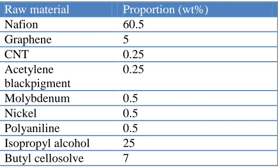
Table 1. Raw materials and proportion of the conductive grapheme-based solution.
Raw material Proportion (wt%)
Nafion 60.5
Graphene 5
CNT 0.25
Acetylene blackpigment
0.25
Molybdenum 0.5
Nickel 0.5
Polyaniline 0.5
Isopropyl alcohol 25 Butyl cellosolve 7
To enhance the hydrophilic capability of IPMC, we constructed an experimental apparatus in air shown in Fig. 1(a) and an experimental simulator in seawater shown in Fig. 1(b), and then, we tested the performance of the IPMC with a variety of conductive graphene-based solutions in both the air and seawater. The test was conducted by applying the same bending motions to the IPMC samples while the frequencies were varied from 0.03 Hz to 1 Hz. Due to their inherent flexibility, mechanoelectric coupling, ability to operate in both water and air, and long operating life, IPMCs are excellent candidates for harvesting energy in the low frequency regime.
[image:4.596.71.527.435.695.2]
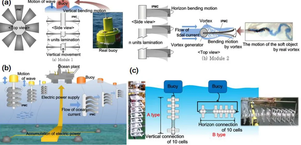
The ocean kinetic energy harvesting module consists of nine vertical and nine horizontal components with ten cells. The cell has two upper and lower mold injected plastic square-shaped frames, an IPMC between two graphite electrodes in every face and a circuit for rectifying and parallel collecting electricity. The entire cell is waterproof. Both the vertical and horizontal components have a sub-buoy sufficient to float on the surface of the seawater, and each component composed of ten cells has an electricity collector in parallel located on the sub-buoy. A main buoy, which is composed of eighteen components, consists of an electricity collector in parallel with power measurement and a communication module with a photovoltaic power supply that wirelessly sends data to a monitoring system. Nine vertical and nine horizontal components, which are placed on the left and right sides of the main buoy, respectively, are connected to each other with ropes, and the main buoy is fixed to the seafloor with four anchors.
[image:5.596.57.546.396.633.2]Based on the results of the IPMC sample performance with the conductive graphene-based solution and the investigation of the marine physics, we optimized the total active area of the ocean kinetic energy harvesting module with IPMC. The performance of the IPMC with the electrical conductive graphene-based solution is slightly worse than that with the platinum complex solution. Therefore, a less than one and half times broader active area was prepared (i.e., 16,200 cm2), which consists of eighteen for each component containing ten cells with an active area of 900 cm2.
We designed a movable power system utilizing both vertical waves and horizontal ocean currents using the electrochemical material consisting of IPMC to supply electricity to stand-alone offshore plants, as shown in Figs. 2(a), 2(b) and 2(c). Water movements are a combination of both transverse and longitudinal components. The transverse component accounts for the vertical motion of waves, and the longitudinal component refers to the horizontal motion of ocean currents, as shown in Fig. 2(c) [20-22].
3. RESULTS AND DISCUSSION
3.1 SEM analyses of electrochemical materials
The different sized particles were used to improve the conductivity and abrasion resistivity by filling the spaces between larger particles with the relatively small particles upon mixing. The first group consists of carbon-based particles including graphene and single wall carbon nanotubes obtained from WorldTube, Inc. in South Korea, which have a particle size distribution ranging from 50 to 100 nm. Because the single wall carbon nanotubes (CNTs) exhibit a strong absorption characteristic, only a small portion (i.e., 0.25 wt%) was used. The second group consists of a conductive polymer and a conductive black pigment. 0.5 wt% of the conductive polymer (i.e., polyaniline) and 0.25 wt% of a conductive pigment (i.e., acetylene black), which has needle type crystals that can improve conductivity by connecting to other particles, were used. The mean particle sizes of these materials were 30 nm and 100 nm, respectively. The third group consists of metal-based particles including molybdenum and nickel powders that have relatively large particle sizes, which range from 15 m to 20 m, and improve the conductivity of the ink. 25 wt% of isopropyl alcohol was added to improve the adhesion of the ink to the Nafion film and to dissolve the particles. 7 wt% of butyl cellosolve was added to control the volatility of the ink. All of the materials were mixed using high speed dispersion with zirconium beads. After the ink was applied to the surface of the Nafion 117 membrane using an air spray, the membrane was fully dried at 140 in oven for 1 hour.
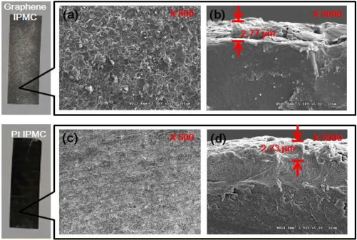
Figure 3. SEM image comparison of graphene based IPMC and platinum based IPMC. (a) Surface SEM image of graphene based IPMC. (b) Cross sectional SEM image of graphene based IPMC. (c) Surface SEM image of platinum based IPMC. (d) Cross sectional SEM image of platinum based IPMC.
3.2 Laboratory scale test for harvesting electrical energy
[image:7.596.53.554.73.410.2]
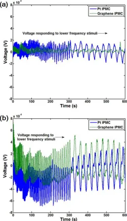
Figure 4. Performance comparison of the IPMC samples with the conductive graphene-based solution and Pt complex solution in air and seawater with the IPMC samples of 1 cm × 4 cm. (a) Voltages observed for the IPMC sample of the conductive graphene-based solution and Pt complex solution due to bending in air. (b) Voltages observed with the IPMC sample of the conductive graphene-based solution and the Pt complex solution utilizing both vertical waves and horizontal ocean currents in the seawater simulator
3.3 Marine physics investigation
[image:8.596.172.423.73.508.2]
harvesting structure. Fig. 5(b) shows the flow velocities and directions of seawater measured at the surface, middle and bottom by an acoustic Doppler current profiler (ADCP).
[image:9.596.123.475.130.635.2]
From the statistical analysis of the raw data obtained with the ADCP [24], the maximum flow velocities at the surface, middle and bottom were 15.1 cm/s, 13.4 cm/s and 16.1 cm/s, respectively, and the flux emergency rates under 10 cm/s at the surface, middle and bottom were 99.1%, 99.3% and 98.7%, respectively. In addition, the emergency rates for the south direction flow at the surface, middle and bottom were 61.9%, 57.6% and 56.2%, respectively, while the emergency rates for the north direction flow at the surface, middle and bottom were 38.2%, 42.4% and 43.8%, respectively. Therefore, the emergency rate of the south direction flow was higher than that of the north direction flow, as shown in Fig. 5(c). Based on ISO tidal analysis [24], the progressive vectors of the ocean currents are calculated at the surface, middle and bottom for a 15-day observation period, as shown in Fig. 5(d).
3.4 Performance test of ocean kinetic energy harvesting module
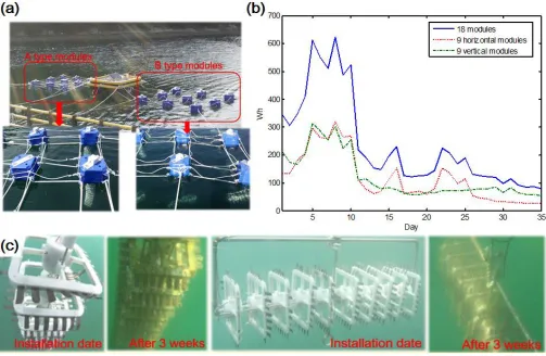
The ocean kinetic energy harvesting module, shown in Fig. 6(a), produced electrical energy after installation at the IP on August 24, 2013. The main buoy measured the electrical energy harvested with the module. Fig. 6(b) shows the extremely variable data obtained over 5 weeks starting on September 5, 2013 and continuing for 35 days. The module produced electrical energy over the target of 120 Wh and up to 600 Wh for approximately 10 days in the graph and approximately 20 days from the initial installation. The electrical energy produced gradually decreased to less than 120 Wh.
The instantaneous power density of IPMC with platinum electrodes of 10 mm (width) 50 mm (length) 0.2 mm (thickness) for tip excitation was measured to be around 45 W/cm3 in air. The electrical energy target of 120 Wh is converted to the instantaneous power density of approximately 267 W/cm3 which is greater than around 45 W/cm3 in air [19]. Sodium ions, which are surrounded by free water molecules, move to the anode. Selective ionic and water transport across the polymer under an electric field result in volumetric changes, which promotes the energy harvest. The electrical energy at approximately day 10 significantly decreased because it is estimated that the kinetic energy of the waves and ocean currents is weak in the ocean. The growth of algae and barnacles on the module retard the IPMC bending motion and disrupt harvesting of the electrical energy, as shown in Fig. 6(c).
Figure 6. Performance of the ocean kinetic energy harvesting module with the conductive graphene-based solution IPMC. (a) Photograph of the ocean kinetic energy harvesting module. (b) History of the electrical energy harvested with the ocean kinetic energy harvesting module from ocean currents and waves. (c) Photographic comparison of the vertical and horizontal components between the day of installation and after 3 weeks.
4. CONCLUSIONS
To generate electricity from the kinetic energy in the ocean, we developed the world’s first movable ocean kinetic energy harvesting module with an electrochemical material consisting of IPMC that replaces fixed tidal power generation to drive turbines using ocean flow. Ultimately, we constructed a movable module for stand-alone offshore plants such that the power grid is out of reach to accommodate situations that require reduced costs and expanded coverage.
During the course of our experiments, we encountered unexpected growth of algae and barnacles that affect electrochemical conversion with IPMC. Therefore, our goal is to develop a material or a structure that coexists with the ocean, which is a complex three-dimensional world, and would advance both conservation and development of marine resources.
ACKNOWLEDGEMENTS
[image:11.596.59.562.77.405.2]
Refernces
1. N. Tanaka, Ed., Energy Technology perspectives 2010: scenarios & strategies to 2050, OECD/IEA, Paris France (2010).
2. S. H. Salter, Nature 249 (1974) 720.
3. D. V. Evans, Annu. Rev. Fluid Mech. 13 (1981) 157.
4. J. Falnes, Ocean Waves and Oscillating Systems, Linear Interaction Including Wave Energy Extraction, Cambridge Univ. Press, Cambridge (2002).
5. Q. Schiermeier, Nature, 447 (2007) 522.
6. E. D’Asaro, C. Lee, L. Rainville, R. Harcourt and L. Thomas, Science,,332 (2011) 318. 7. J. Scruggs and P. Jacob, Science, 323 (2009) 1176.
8. J. Cruz, Ed., Ocean Wave Energy: Current Status and Future Perspectives, Springer, Berlin Germany (2008).
9. E. Callaway, Nature, 450 (2007) 156. 10. J. Mackinnon, Nature, 501 (2013) 321.
11. M. Rahm, C. Boström, O. Svensson, M. Grabbe, F. Bülow and M. Leijon, IET Renew. Power Gen., 4 (2010) 602.
12. A. Muetze and J. G. Vining, Proceedings of the IEEE IAS’06 (2006) March; Tampa, USA. 13. J. Sjolte, G. Tjensvoll and M. Molinas, Appl. Sci., 3 (2013) 420.
14. A. Blavette, D. O’Sullivan, A. Lewis and M. Egan, Proceedings of the OCEANS conference (2012) May 21-24; Yeosu, KOREA.
15. M. Rahm, O. Svensson, C. Boström, R. Waters and M. Leijon, IET Renew. Power Gen., 6 (2012) 149.
16. J. Kahn, G. Bhuyan and Ed., Ocean energy: Global technology development status, IEA-OES, British Columbia CANADA (2009).
17. G. Bracco, E. Giorcelli and G. Mattiazzo, Mech. Mach. Theory, 46 (2011) 1411. 18. Z. Chen and X. Tan, Sensor Actuat. A-Phys., 157 (2010) 246.
19. R. Tiwari and K. J. Kim, Smart Mater. Struct., 22 (2013) 015017. 20. J. Smagorinsky, Mon. Wea. Rev., 91 (1963) 99.
21. A. Giacomello and M. Porfiri, J. Appl. Phys., 109 (2011) 084903.
22. L. A. Weinstein, M. R. Cacan, P. M. So and P. K. Wright, Smart Mater. Struct., 21 (2012) 045003. 23. K. Oberg, D. S. Mueller and M.ASCE, J. Hydraul. Eng., 133 (2007) 1421.
24. J. Kim, S. Yun and Z. Ounaies, Marcomolecules, 39 (2006) 4202.