Int. J. Electrochem. Sci., 8 (2013) 1999 - 2008
International Journal of
ELECTROCHEMICAL
SCIENCE
www.electrochemsci.orgDetermination of Clonidine by Potentiometry Using PVC
Membrane Electrode
Mohammad Reza Ganjali1,2,*,Anahita Karimi1, Sayed Jamaleddin Shahtaheri,3 Parviz Norouzi1,2
1
Center of Excellence in Electrochemistry, University of Tehran, Tehran, Iran
2
Endocrinology & Metabolism Research Center, Tehran University of Medical Sciences, Tehran, Iran
3
Department of Occupational Health, School of Public Health, Center for Environmental Research, Tehran University of Medical Sciences, Tehran, Iran
*
E-mail: ganjali@khayam.ut.ac.ir
Received: 29 November 2012 / Accepted: 26 December 2012 / Published: 1 February 2013
PVC membrane potentiometric sensor was made for determination of Clonidine in pharmaceutical formulations. The electrode respond based on ion-exchange mechanism. The ion-pair used as a sensing element in PVC membrane composition was synthesized by interaction of Clonidine hydrochloride and tetraphenyl borate. The best PVC membrane sensor response was obtained by a membrane composition of 30% PVC, 62% DBP, 6% ion-pair and 2% ionic liquid. The proposed method was successfully applied in determination of Clonidine in some formulations. The proposed sensor showed a linear dynamic range between 7.0×10⁻⁶-1.0×10⁻² M of Clonidine with a Nernstian slope of (58.3 ±0.4) mV decade-1
and a detection limit of 6.5×10⁻⁶ M. The proposed electrode displayed fast response time about 10 s, and lifetime of about six weeks without any significant change in its performance.
Keywords: Clonidine, Potentiometric Sensor, PVC membrane Electrode, Ion-Pair
1. INTRODUCTION
N
NH Cl H
N
[image:2.596.240.357.89.174.2]Cl
Figure 1. Chemical structure of Clonidine
Some techniques are reported to determine clonidine such as, radio-immunoassay [5], gas chromatography (GC) [6], colorimetry [7], high performance liquid chromatography (HPLC) [8], and capillary isotachophoresis [9].
Potentiometric using indicator electrodes have advantages of rapid and ease of preparation and procedures, fast response time, reasonable selectivity, wide linear dynamic range, and low cost. These characteristics have certainly led to the preparation of numerous sensors for several ionic species, and the list of available electrodes has grown largely over the past years [10-21].
PVC membrane electrodes are one of the subdivisions of potentiometric sensors which are widely used and have different application in analysis of ionic species [22-32].
In this work, electrode work based on ion-pair which was made from the interaction between clonidine and sodium tetraphenyl borate and they respond according to the ion-exchange mechanism. PVC membrane electrode was made after series of experiments.
2. EXPERIMENTAL SECTION
2.1. Apparatus
The glass cell where the clonidine indicator electrode (PVC membrane) was placed; consisted of two Ag/AgCl double junction reference electrodes (Azar-Elelectrode Co., Iran) as internal and external reference electrodes. Both electrodes were connected to a Corning ion analyzer with a 250 pH/mV meter with ±0.1 mV precision.
2.2. Materials and Reagents
Chemicals (of analytical reagent grade) were: high-molecular weight polyvinylchloride (PVC) (Fluka Co., USA), room temperature ionic liquid (1-n-butyl-3-methylimidazolium tetrafluoroborate ([bmim]BF4), sodium tetraphenyl borate (NaTPB), nitrophenyloctylether (NPOE), dibutyl phthalate
2.3. Preparation of the ion-pair
Sensing element used in the sensors was an ion-pair compound made from the interaction of clonidine and sodium tetraphenyl borate. It was prepared by mixing about 20 mL of 0.01 M acidic solution of clonidine hydrochloride with 20 mL tetraphenyl borate solution. The resulting precipitate was then filtered, washed with distilled water and dried in room temperature [21,23].
2.4. Preparation of PVC membrane Electrodes
General procedure to prepare PVC membrane was as follow: different amounts of ion-pair along with appropriate amounts of PVC, plasticizer and additive were dissolved in tetrahydrofuran (THF), and the solution was mixed well into a glass dish of 2 cm diameter. Then, THF was evaporated slowly until an oily concentrated mixture was obtained. A plastic tube (about 3 mm o.d.) was dipped into the mixture for about 10 s so a transparent membrane of about 0.3 mm in thickness was formed. The tube was then pulled out from the mixture and kept at room temperature for about 5 h. Afterwards, the tube was filled with an internal filling solution (1.0×10⁻³ M of Clonidine hydrochloride solution). The electrode was finally conditioned for 20 h by soaking in the same solution [18-23].
2.5. Standard Clonidine solutions
A stock solution of 0.02 M Clonidine hydrochloride solution was prepared. The working standard solutions (1×10⁻⁷ to 1×10⁻² M) were prepared by appropriately dilution of the stock solution with distilled water.
2.6. The emf Measurements
Following cell assembly for the conduction of emf (electromotive force) measurements were used:
Ag-AgCl || internal solution, 1×10⁻³ M Clonidine hydrochloride solution | PVC membrane | sample solution || Ag-AgCl, KC1 (satd.)
These measurements were done using calibration of the electrodes with several standard solutions.
3. RESULTS AND DISCUSSION
3.1. PVC Membrane Composition Selection
the relative amount of the membrane components of the electrode. The main components of a membrane are PVC matrix, plasticizer and the ion-pair as a sensing material. Each membrane component plays a special role in the membrane function and electrode response. Previous studies shows that the membrane prepared with a plasticizer/PVC ratio about 2.2 can show the best performance [39-46].
[image:4.596.51.545.302.585.2]Plasticizer which mainly acts as a membrane solvent allowing homogeneous dissolution and diffusional mobility of the ion-pair inside the membrane [47-52]. The plasticizer should be water-immiscible liquid with low vapor-pressure, compatible with PVC, no functional groups which can undergo protonation reactions. The selectivity of such electrode can be drastically influenced by the choice of the membrane solvent [45-55].
Table 1. Optimization of the membrane components and response of the electrode
Entry PVC Plasticizer Ion-pair RTIL Slope*
(mV/decade)
LR (M)* DL (M)* R2
1 30 DBP,68 2 - 18.3±0.7 1.0×10⁻³-5.0×10⁻³ 1.0×10⁻³ 0.850
2 30 DBP,66 4 - 34.8±0.6 5.0×10⁻⁴-5.0×10⁻³ 4.5×10⁻⁴ 0.920
3 30 DBP,64 6 - 52.1±0.5 5.0×10⁻⁵-1.0×10⁻² 1.5×10⁻⁵ 0.934
4 30 DBP,62 8 - 50.1±0.6 1.0×10⁻⁴-1.0×10⁻² 6.5×10⁻⁵ 0.919
5 30 NB,64 6 - 38.0±0.5 7.0×10⁻⁴-5.0×10⁻² 5.0×10⁻⁴ 0.910
6 30 BA,64 6 - 27.6±0.7 1.0×10⁻⁴-3.0×10⁻² 1.0×10⁻⁴ 0.926
7 30 NPOE,64 6 - 45.3±0.5 7.0×10⁻⁴-1.0×10⁻² 5.0×10⁻⁴ 0.945
8 30 DBP,63 6 1 55.0±0.3 1.0×10⁻⁵-1.0×10⁻² 1.0×10⁻⁵ 0.959
9 30 DBP,62 6 2 58.3±0.4 7.0×10⁻⁶-1.0×10⁻² 6.5×10⁻⁶ 0.997
10 30 DBP,61 6 3 57.7±0.6 8.0×10⁻⁶-1.0×10⁻² 7.5×10⁻⁶ 0.994
11 30 DBP,68 0 2 4.6±0.8 1.0×10⁻³-3.0×10⁻³ 1.0×10⁻³ 0.880
*The results are base on five replicate measurements.
As it can be seen from Table 1, absence of ion-pair in the membrane causes a very poor response (membrane no. 11), which confirm significance of the ion-pair.
The electrodes behavior show that the best Nernstian slope is 58.3±0.4 mV per decade. Finally, membrane no. 9 with the composition of 30% PVC, 6% ion-pair, 2% RTIL and 62% DBP was the optimum one for the sensor design.
3.2. Calibration Graph and Statistical Data
The calibration graph i s shown in Figure 2. Measurements could be performed in this range, but noted that more closely spaced calibration points are required for more precise determinations [48-55]. Calibration graph slope for PVC membrane electrode is 58.3 mV per decade of Clonidine concentration and a standard deviation of ±0.4 mV after five replicate measurements. A linear response towards the Clonidine concentration was from 7.0×10⁻⁶-1.0×10⁻² M. In this work, detection limit of the PVC membrane sensor was 6.5×10⁻⁶ M which was calculated by extrapolating the two segments of the calibration curves.
y = -58.29x + 577.0 R² = 0.997
100 150 200 250 300 350 400 450 500
0 1
2 3
4 5
6 7
8
E
/
m
V
-log [Clomiphene]
[image:5.596.134.472.368.680.2]
3.3. Dynamic Response Time
Dynamic response time is the required time for the electrode to achieve values within ±1 mV of the final equilibrium potential, after successive immersions in the sample solutions [46-51]. Its calculation involved the variation and the recording of the Clonidine concentration in a series of solutions from 1.0×10⁻⁵ to 1.0×10⁻² M. Sensor was able to quickly reach its equilibrium response in the whole concentration range. This time for PVC membrane electrode was about 10 s in the concentrated solutions.
3.4. pH Effect on the Electrodes Response
To examine the effect of pH on the electrode responses, the potential was measured at specific concentration of the Clonidine solution (1.0×10⁻⁴ M) from the pH value of 1.0 up to 10.0 (concentrated NaOH or HCl solutions were employed for the pH adjustment) by PVC membrane electrode. The results showed that the potential remained constant despite the pH change in the range of 3.5 to 6.0 which indicates the applicability of this electrode in the specified pH range.
Relatively noteworthy fluctuations in the potential vs. pH behavior took place below and above the formerly stated pH limits. In detail, the fluctuations above the pH value of 6.0 might be justified by removing the positive charge on the drug molecule. Fluctuations below the pH value of 3.5 were caused by removal of the membrane ingredients or analyte in the solution. In both electrodes the same trend were observed.
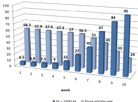
3.5. Life-time Study
Electrode lifetime was estimated by the calibration curve, periodical test of a standard solution and calculation of its response slope.
0 10 20 30 40 50 60 70 80 90 100
1 2
3 4
5 6
7 8
9 10
6.5 6.8 7.5 9 15
27 41
67 84
95
58.3 57.9 57.6 57.3 57 56.5
51 45
33
24
week
[image:6.596.198.435.543.719.2]DL x 10(6) M Slope mV/decade
For this estimation, three electrodes were employed extensively (1 hour per day) for 10 weeks. After 6 weeks utilization of PVC membrane electrode, two changes a gradual decrease in the slope and an increase in the detection limit as can be seen in Fig. 3 were observed.
In PVC membrane electrodes after several time of usage, the membrane ingredients leak from the organic layer and affect the membrane response.
3.6. Analytical Applications
Linearity, limit of detection, recovery test, selectivity, precision, accuracy, and ruggedness/robustness were the parameters used for the method validation.
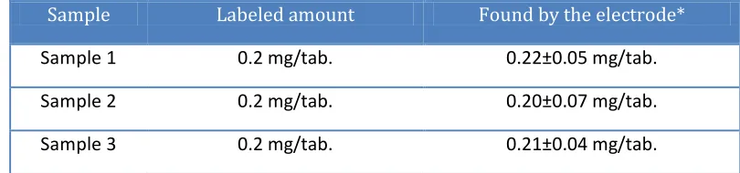
3.6.1. Recovery Test from Tablet
[image:7.596.93.498.436.531.2]The proposed sensor was evaluated by measuring the drug concentration in some pharmaceutical formulations (Clonidine amount of some tablets) (Table 2). The drug concentration was determined using calibration method. The results are in satisfactory agreement with the labeled amounts.
Table 2. Potentiometric determination of Clonidine in pharmaceutical formulations
Sample Labeled amount Found by the electrode*
Sample 1 0.2 mg/tab. 0.22±0.05 mg/tab.
Sample 2 0.2 mg/tab. 0.20±0.07 mg/tab.
Sample 3 0.2 mg/tab. 0.21±0.04 mg/tab.
* The results are based on five replicate measurements.
3.6.2. Selectivity
Table 3. Selectivity coefficients of various interfering compounds for Clonidine sensor
Interfering ion Log (KMPM)
Na+ -3.9
K+ -3.6
NH4+ -3.2
Ca2+ -3.6
Mg2+ -3.8
Lactose -4.5
Glucose -4.5
presence of interfering ions, is the most important characteristic of these devices. The potentiometric selectivity coefficients of the Clonidine sensor were evaluated by the matched potential method (MPM) [56-62]. The resulting values of the selectivity coefficients are shown in Table 3. Note that all selectivity coefficients shows the interferences a r e negligible in the performance of the electrode assembly.
3.6.3. Precision and accuracy
For repeatability monitoring, 3 standard samples were measured. The RSD values by PVC membrane were 3.5, 3.7 and 4.1%.
3.6.4. Ruggedness/Robustness
For ruggedness of the methods a comparison was performed between the intra- and inter-day assay results for Clonidine obtained by two analysts.
The RSD values for the intra- and inter-day assays in the cited formulations performed in the same laboratory by the two analysts did not exceed 3.8%. On the other hand, the robustness was examined while the parameter values (pH of the solution and the laboratory temperature) changed slightly. Clonidine recovery percentages were good under most conditions, and not showing any significant change when the critical parameters were modified.
4. CONCLUSIONS
In the present work, potentiometric electrode was constructed for determination of Clonidine. The best PVC membrane sensor response was obtained by a membrane composition of 30% PVC, 62% DBP, 6% ion-pair and 2% ionic liquid. The proposed method was successfully applied in determination of Clonidine in some formulations. The proposed sensor showed a linear dynamic range between 7.0×10⁻⁶-1.0×10⁻² M of Clonidine.
ACKNOWLEDGEMENT
The authors are grateful to the Research Council of University of Tehran for the financial support of this work.
References
1. C. Dollery (Ed.), Therapeutic Drugs, 2nd ed., Churchill Livingstone Publication, p. C294. 2. C.A. Hamilton, Pharmacol. Ther., 54 (1992) 231.
3. B. Jarrot, E. L. Comway, C. Maccarone, and S. J. Lewis, Clin. Exp. Pharmacol., 14 (1987) 471. 4. J. C. Eisenach, M. De Knock, and W. Klimscha, Anesthesiology, 85 (1996) 655.
6. S. Rossi, and T. Yaksh, J. Pharm. Biomed. Anal. 31 (2003) 243.
7. Ch P (Vol II) Chinese Pharmacopoeia, Chinese Pharmacopoeial Convention, Beijing (2000) 8. A. M. Classen, G. H. Wimbish, and T. C. Kupiec, J. Pain. Symptom. Manag. 28 (2004) 603 9. A. Hercegova, J. Sadecka, and J. Polonsky, Acta Pol. Pharm., 55 (1998) 167
10.M. R. Ganjali, T. Razavi, F. Faridbod, S. Riahi, and P. Norouzi, Curr. Pharm. Anal. 5 (2009) 28. 11.F. Faridbod, M. Khamseh-Nejad, M. R. Ganjali, P. Norouzi, and L. Hajiaghababaei, Inter. J.
Electrochem. Sci., 7 (2012) 1917.
12.F. Faridbod, M. R. Ganjali, R. Dinarvand, and P. Norouzi, Sensors, 8 (2008) 2331.
13.M. R. Ganjali, R. Nemati, F. Faridbod, P. Norouzi, and F. Darviche, Int. J. Electrochem. Sci. 3 (2008) 1288.
14.M. R. Ganjali, T. Poursaberi, F. Basiripour, M. Salavati-Niasari, M. Yousefi, and M. Shamsipur, Fresenius J. Anal. Chem., 370 (2001) 1091.
15.H. A. Zamani, M. Mohammadhosseini, S. Haji-Mohammadrezazadeh, F. Faridbod, M. R. Ganjali, S. Meghdadi, and A. Davoodnia, Mater. Sci. Eng. C, 32 (2012) 712.
16.M. R. Ganjali, A. Karimi, and P. Norouzi, Int. J. Electrochem. Sci., 7 (2012) 3681.
17.F. Faridbod, T. Poursaberi, P. Norouzi, and M. R. Ganjali, Int. J. Electrochem. Sci., 7 (2012) 3693. 18.M.R. Ganjali, B. Larijani, and P. Norouzi, Int. J. Electrochem. Sci., 15 (2012) 4822.
19.M. R. Ganjali, M. Emami, M. Rezapour, M. Shamsipur, B. Maddah, M. Salavati-Niasari, M. Hosseini, and Z. Talebpoui, Anal. Chim. Acta, 495 (2003) 51.
20.M. R. Ganjali, T. Alizadeh, B. Larijani, F. Faridbod, and P. Norouzi, Int. J. Electrochem. Sci. 7 (2012) 4756.
21.F. Faridbod, M. R. Ganjali, B. Larijani, E. Nasli-Esfahani, S. Riahi, and P. Norouzi, Int. J. Electrochem. Sci., 5 (2010) 653.
22.S. K. Mittal, P. Kumar, S. K. Ashok Kumar, and L. F. Lindoy, Int. J. Electrochem. Sci., 5 (2010) 1984.
23.F. Faridbod, M. R. Ganjali, L. Safaraliee, S. Riahi, M. Hosseini and P. Norouzi, Int. J. Electrochem. Sci., 4 (2009) 1419.
24.V. K. Gupta, R. Ludwig and S. Agarwal, Anal. Chim. Acta, 538 (2005) 213.
25.M.R. Ganjali, H.A. Zamani, P. Norouzi, M. Adib, and M. Accedy, Acta Chim. Slov., 52 (2005) 309.
26.R. K. Bera, S. K. Sahoo, S. K. Mittal, and S.K.A. Kumar, Int. J. Electrochem. Sci., 5 (2010) 29. 27.H. A. Zamani, R. Kamjoo, M. Mohammadhosseini, M. Zaferoni, Z. Rafati, M. R. Ganjali, F.
Faridbod, and S. Meghdadi, Mater. Sci. Eng. C, 32 (2012) 447.
28. H. A. Zamani, M. R. Ganjali, H. Behmadi, and M. A. Behnajady, Mater. Sci. Eng. C, 29 (2009) 1535.
29. S. K. Srivastava, V. K. Gupta, S. Jain, Electroanalysis, 8 (1996) 938.
30. M. R. Abedi, H. A. Zamani, M. R. Ganjali, and P. Norouzi, Sensor Lett., 5 (2007) 516. 31. A. K. Singh, V. K. Gupta and B. Gupta, Anal. Chim. Acta, 1 (2007) 171.
32. M. R. Ganjali, A. Daftari, P. Nourozi and M. Salavati-Niasari, Anal. Lett., 36 (2003) 1511. 33.M. Javanbakht, A. Badiei, M. R. Ganjali, P. Norouzi, A. Hasheminasab and M. Abdouss, Anal.
Chim. Acta, 601 (2007) 172.
34.G. A. M. Mersal, and H. A. Arida, Int. J. Electrochem. Sci., 6 (2011) 1116.
35.M. R. Ganjali, H. Khoshsafar, A. Shirzadmehr, M. Javanbakht and F. Faridbod, Int. J. Electrochem. Sci., 4 (2009) 435.
36.S. Reddy, B.E. Kumara Swamy, U. Chandra, B.S.Sherigara, and H. Jayadevappa, Int. J. Electrochem. Sci., 5 (2010) 10.
37.F. Faridbod, F. Mizani, M. R. Ganjali, and P. Norouzi, Int. J. Electrochem. Sci., 7 (2012) 7643. 38.A. C. Oliveira and L. H. Mascaro, Int. J. Electrochem. Sci., 6 (2011) 804.
39.H. A. Zamani, M. R. Ganjali, and M. Adib, Sensor Lett. 4 (2006) 345.
Mater. Sci. Eng. C, 29 (2009) 976.
41.H. A. Zamani, M. R. Ganjali, P. Norouzi, and S. Meghdadi, J. Appl. Electrochem., 37 (2007) 853. 42.M. R. Ganjali, S. Rasoolipour, M. Rezapour, P. Norouzi, A. Tajarodi, Y. Hanifehpour,
Electroanalysis, 17 (2005) 1534.
43.V. K. Gupta, A. K. Singh and B. Gupta, Anal. Chim. Acta, 575 (2006) 198.
44.H.A. Zamani, M. Nekoei, M. Mohammadhosseini, and M.R. Ganjali, Mater. Sci. Eng. C, 30 (2010) 480.
45.H. A. Zamani, F. Malekzadegan, and M. R. Ganjali, Mater. Sci. Eng. C, 28 (2008) 157. 46.F. Faridbod, M. R. Ganjali, E. Nasli-Esfahani, B. Larijani, S. Riahi, and P. Norouzi, Int. J.
Electrochem. Sci., 5 (2010) 880.
47.M. R. Ganjali, P. Norouzi, A. Atrian, F. Faridbod, S. Meghdadi, M. Giahi, Mater. Sci. Eng. C 29 (2009) 205.
48.V. K. Gupta, R. Mangla and S. Agarwal, Electroanalysis, 14 (2002) 1127.
49.M. R. Ganjali, H. Shams, F. Faridbod, L. Hajiaghababaei, P. Norouzi, Mater. Sci. Eng. C, 29 (2009) 1380.
50.A. K. Jain, V. K. Gupta, L. P. Singh, P. Srivastava and J. R. Raisoni, Talanta, 65 (2005) 716. 51.M. Masrournia, H. A. Zamani, H. A. Mirrashid, M. R. Ganjali, F. Faridbod,, Mater. Sci. Eng. C, 31
(2011) 574.
52.H. A. Zamani, B. Feizyzadeh, F. Faridbod, and M. R. Ganjali, Mater. Sci. Eng. C 31 (2011) 1379. 53.M. R. Ganjali, F. Faridbod, B. Larijani, S. Riahi, M. Hosseini, E. Nasli-Esfahani, P. Norouzi, Int. J.
Electrochem. Sci., 6 (2011) 200.
54.M. R. Ganjali, P. Norouzi, M. Adib, and A. Ahmadalinezhad, Anal. Lett., 39 (2006) 1075. 55.M. R. Ganjali, F. Faridbod, H. Rashedi, M. Hosseini, and P. Norouzi, Int. J. Electrochem. Sci., 6
(2011) 2299.
56.H. A. Zamani, M. R. Ganjali, F. Faridbod, and M. Salavati-Niasari, Mater. Sci. Eng. C, 32 (2012) 564.
57.H. A. Zamani, M. R. Ganjali, P. Norouzi, A. Tadjarodi, and E. Shahsavani, Mater. Sci. Eng. C 28 (2008) 1489.
58.M. R. Ganjali, H. Haji-Hashemi, F. Faridbod, P. Norouzi, M. Qomi, Int. J. Electrochem. Sci., 7 (2012) 1470.
59.M. Shamsipur, M. Yousefi, M. Hosseini, and M. R. Ganjali, Anal. Lett., 34 (2001) 2249. 60.M. R. Ganjali, P. Norouzi, F. Faridbod, S. Riahi, J. Ravanshad, J. Tashkhourian, M.
Salavati-Niasari, and M. Javaheri, IEEE Sensors J., 7 (2007) 544. 61.P. R. Buck, and E. Lindneri, Pure Appl. Chem. 66 (1994) 2527.
62.P. Norouzi, H. Rashedi, A. Alipour, F. Faridbod, S. J. Shahtaheri, and M. R. Ganjali, Int. J. Electrochem. Sci., 6 (2011) 2312.