Int. J. Electrochem. Sci., 7 (2012) 601 - 614
International Journal of
ELECTROCHEMICAL
SCIENCE
www.electrochemsci.orgElectroplating Nanostructured Hard Gold through the Pulse
Galvanostatic Method
Hassan Karami1,2,*, Hamid Babaei3
1
Nano Research Laboratory, Department of Chemistry, Payame Noor University, Abhar, Iran
2
Department of Chemistry, Payame Noor University, 19395-4697, Tehran, I.R. of Iran
3
Department of Chemistry, Islamic Azad University, Central Tehran Branch, Tehran, Iran
*
E-mail: [email protected]
Received: 13 October 2011 / Accepted: 9 December 2011 / Published: 1 January 2012
The present work shows a full study of the pulse electroplating of cobalt hard gold on a nickel substrate. Certain parameters in the pulse galvanostatic method, including pulse height (current amplitude), relaxation time (toff), pulse time (ton) and bath temperature, were effectively optimized by
the “one at a time" method to obtain a suitable nanostructured layer. SEM, XRD, EDS, micro-hardness testers, roughness measuring instruments and the Auto Lab electrochemical analyzer were utilized in studying the influence of pulse electrodeposition variables on the surface morphology, particles sizes, film composition, mechanical characteristics and electrochemical behaviors of the deposited layer. The obtained results indicate that under the optimized conditions for pulse electroplating, the pulse height, the toff, the ton, and the bath temperature are 3 mA.cm-2, 1.5 s, 0.5 s, and 25 °C respectively. The
electroplated surface in the optimum conditions includes a uniform nanostructured layer with low porosity and fine grains, with an average diameter of 70 nm which has excellent mechanical and electrochemical properties such as hardness and anticorrosion.
Keywords: Pulse electroplating, Pulse galvanostatic, Nanostructured hard gold, gold-cobalt alloys, Pusle current
1. INTRODUCTION
morphology of the electrodeposits, which may also improve its other mechanical and electrical properties [2].
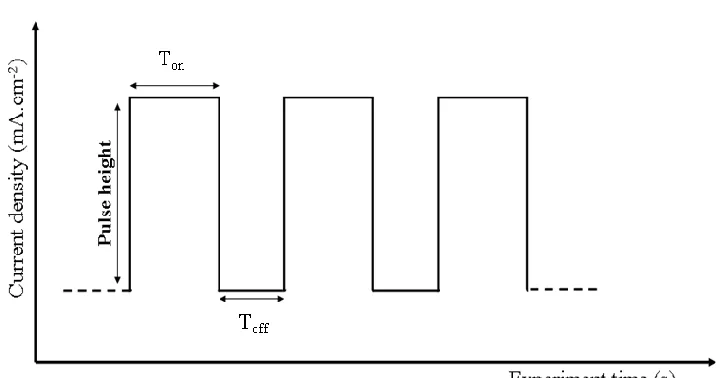
The electrodeposition of nanostructured coatings by pulse current often proceeds as a parametric study [3]. That is, the variables of the process that can produce a refined grain size in the deposit are optimized through experimental iteration [3]. In the conventional dc plating there is only one parameter, called the current density, which can be varied. In pulse electroplating, there are at least three parameters, including pulse height (current amplitude), relaxation time (toff) and pulse time (ton)
whose values can be effectively optimized. Each pulse consists of a ton during which the potential or
the current is applied, and a toff during which the zero current is applied as shown in Fig. 1. In the
current pulse, the duty cycle (γ) corresponds to the percentage of the total time of a cycle and is given by [4, 5]:
100 100
) /(
% ton tontoff fton (1)
Where, f is the pulse frequency that defined as the reciprocal of the cycle time (t). I avg (average current density) is calculated from [6]:
) /( on off
on P
avg I t t t
I (2)
Where, Ip is the pulsed current density.
Figure 1. Typical pulse-current diagram
[image:2.596.115.475.439.628.2]
periodically turned off to cause this layer to discharge to an extent. This process allows the ions to pass through the layer and onto the part more easily [7]. In pulse-plated gold, the polymer is no longer distributed continuously, as observed for dc deposits [8]. Hardness changes only a little or increases slightly by pulse plating [9].Whereas due to voids or inclusions the density of dc plated gold-cobalt (17 g.cm-3) is about 15 per cent less than the theoretical value, the pulse-plated gold cobalt, nearly free of polymer, has a density of 19.2 g.cm-3 which is closer to the theoretical value as determined by the pycnometer method [9].
The reduction in resistivity resulting from pulse plating is more pronounced for gold-cobalt than for high-purity gold [9]. This decrease must be caused by the reduced polymer content or the microstructural difference only, because the cobalt content of pulse-plated deposits is greater by % 25, which should cause an increase in resistivity [9]. The decisive effects of pulse plating are the restoration of the diffusion layer during off-times by gold and cobalt complexes and the removal of byproducts consisting of hydrogen, carbon and nitrogen compounds from the cathode film [9].
As for metal electroplating, pulse electrodeposition is applied to produce a deposit with a finer grain size in comparison with that obtained through direct current (dc) electrodeposition [10-17]. According to the ultimate conclusion of the studies, it is difficult to predict the influence of pulse electroplating parameters on gold or other metals a priori; this is owing to the fact that each electrochemical system reacts in a different way. For example, the grain size in Zn electrodeposition [18] decreases with the pulse time whereas the grain size in Ni electrodeposition [14] increases with the pulse time. Surface roughness is usually related to the grain size of electrodeposited thin films.
To attain comprehensive information about hard gold pulse electroplating, all effective parameters were investigated and optimized through the "one-factor-at-a-time" method by the present study. Hard gold is generally plated from a cyanide bath containing KAu(CN)2 in the presence of a
citrate buffer, and a cobalt or nickel salt as a hardening additive [19,20], although the use of other metals [21,25] and of additive-free gold [26,29] has also been reported.
Some previous reports there are about pulse electroplating and specially about gold electroplating but in any of them, investigation of the effects of the main parameters of a pulsed current technique was not complete [7-17]. In the present work, the effects of all parameters of the pulsed current electroplating technique on the morphology, particles sizes, composition and the electrochemical and mechanical properties of the coated hard gold layer are fully investigated in wide range and optimized by the "one at a time" method. Optimization experiments are carries out to determine the optimized conditions for electrodepositing of hard gold nanostructes. The current report investigates the effects of two important transition metal ions on the morphology, particles sizes and the mechanical properties of the hard gold electrodeposited nanostructured layer.
2. EXPERIMENTAL
2.1. Materials
2. 2. Instrumental
All of the electrodeposition experiments were carried out by a pulse equipped electrolyzer (BTE 04, Iran). After the electrodeposition of the gold alloy on the nickel-coated parts, the morphology and the sizes of the sample particles were studied by means of scanning electron microscopy (SEM; Philips XL-30), and the hardness testing was conducted by the micro-hardness tester M-400. The chemical composition of the alloy was studied and the preferred orientation of the deposit under the optimized conditions was determined by energy-dispersive spectroscopy (Rontec QX2) and X-ray Diffractometer (Bruker D8). Measurements of the surface roughness were obtained through the topographic curves of a surface roughness measuring instrument (Göttingen Mahr M2). Corrosion resistances of the samples synthesized under conventional galvanostatic and pulse galvanostatic methods were studied by Auto Lab (Eco Chimie, PGSTAT 102).
2. 3. Procedure
For this study, the phosphor-bronze sheets were used as the substrate with dimensions of 1cm1cm. The substrate is similar to some electronic connectors which have a copper alloy as the base metal, a layer of nickel as the diffusion barrier and then a layer of gold alloy [2]. The thickness of the nickel layer used on the substrate was about 5-8 µm. Prior to nickel coating, the surfaces of substrates were carefully polished by an automatic polishing and buffing machine. Before gold plating, samples were rinsed with deionized water and immersed in 10% sulfuric acid for 10 minutes, and subsequently double-rinsed with deionized water [2]. The electroplating bath was a cylindrical cell made of stainless steel (316 L) used as the anode. The laboratorial heater/stirrer was used for heating and agitation (350 rpm). A gold-cobalt alloy can generally be plated from a cyanide bath containing KAu(CN)2, citrate
buffer, and a small amount of Co2+ as the hardening agent [19,20], operated at an acidic pH of 4-5 [31, 32]. In the proposed method, the layer of the gold-cobalt alloy was electrochemically deposited on the nickel-coated surfaces from a 30 g.L-1 citric acid and 50 g.L-1 K3C6H5O7, 4 g.L-1 KAu(CN)2 and 2.5
g.L-1 CoSO4. 7H2O solution. The pH of the solution was adjusted to 4-5 [30, 31] by adding KOH
and/or H2SO4 10%, at room temperature. Potassium cyanuarate (KAu(CN)2) does not have suitable
stability in the strong acid media (pH 3 or lower) [19]. The recommended current density in Ref [33] was 1 to 50 A.ft-2, and in the present investigation it was 1-7.5 mA.cm-2. Cheh [34] has done theoretical calculations and experimental measurements which conclusively demonstrate that for phosphate, citrate and cyanide gold electrolytes, the limiting current density is higher in the pulse than in the dc plating because of the higher concentration of gold ions in the diffusion layer, regardless of the fact that the limiting rate of the overall plating is lower. Although the square-wave pulses have been used with periods in the range of 1-10 seconds for a few decades, recent applications tend to use the squre-wave pulse in the millisecond range. The values of the pulse parameters, including pulse amplitude (pulse height or current density), pulse time (ton), relaxation time (toff) and
carried out to determine the chemical composition of the alloy and the preferred orientation of gold-cobalt deposits. The surface roughness was studied by the DIN EN ISO 4287 (1998) standard. The roughening of the surface described by the available parameters mean surface roughness Ra, surface roughness depth Rz, and the maximum grain height Rmax. The electrochemical method was applied to evaluate the performance of the corrosion. The results of the tests on the optimized sample were compared with those obtained from the conventional dc plated sample.
3. RESULTS AND DISCUSSION
In this work, a uniform nanostructured gold-cobalt layer was electrochemically deposited by the pulsed current on nickel-coated surfaces from a solution, including potassium gold cyanide, cobalt sulfate and potassium citrate, under different conditions of electrodeposition, changing the pulse height, the ton, the toff, and the temperature into 1-7.5 mA.cm-2, 0.1-1 s, 0.25- 2 s, and 5- 45 ºC
respectively. The above parameters, including pulse height, relaxation time (toff), pulse time (ton) and
temperature, were optimized by the "one-factor-at-a-time" method. In the following sections, the optimization process will be described.
3. 1. The effect of pulsed current amplitude
Firstly, the effect of the pulse amplitude (current density amount) on the morphology, porosity and hardness of the deposits was investigated.
[image:5.596.95.500.457.708.2]
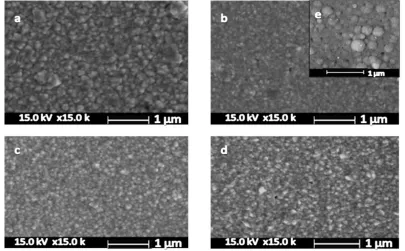
The pulse amplitude was varied from 1 mA.cm-2 to 7.5 mA.cm-2 while the other parameters were kept constant (at 25 ºC, 4 g.L-1 KAu(CN)2, 50 g.L-1 K3C6H5O7, 2.5 g.L-1 CoSO4. 7H2O, 0.5 s Ton,
and 1.5 s Toff ). The morphology and porosity of the deposits were studied using SEM (Fig. 2).
As it can be seen in Fig. 2, the Au–Co electrodeposits have fined grains due to the effect of the pulse current.
The pulsed current amplitude controls the nucleation and particle growth rates of gold. At lower currents, the rate of the particle growth is higher than that of the nucleation; at higher currents, however, the nucleation is of a higher rate. Further, the agglomeration is considerable and the film porosity increases at higher currents as well. Figure 2.b shows that the pulse amplitude of 3 mA.cm-2 causes the most uniformity with indistinguishable grain boundaries and a smaller nanostructure grains diameter than the other current densities. Since the nanoparticles were less than 90 nm in diameter, 3 mA.cm-2 was selected as the optimum current density, though a certain number of voids were noted in image2.e and plated with the conventional dc. In the higher current densities, the Au - Co deposits were dark due to the overpotential and inhibitory of vertical growth of the deposited particles. According to Raub and Knodler, hardness changes only a little or increases slightly through pulse plating [9].
The hardness of coatings was measured under 10 g loading and the full load was applied for 15 s. The hardness of the sample synthesized by 3 mA.cm-2 pulsed current density was measured 160 HV while the same value for the sample electrodeposited by the conventional dc current was 150 HV. The study of the hardening mechanism performed by Lo et al. [35] shows that the major factor determining the hardness is the grain size.
3.2. Optimization of relaxation time (toff)
In order to investigate the effect of the relaxation time on the morphology, porosity and hardness of the deposits, the relaxation time (toff) was varied from 0.25 to 2 seconds at the optimized
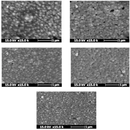
pulsed current while the other parameters were kept constant. Figure 3 displays the SEM images of the different samples which were electrodeposited at different relaxation times.
The SEM images of Fig. 3 indicate that the relaxation times of 1.5 s and higher are more suitable in forming a uniform nanostructured layer with acceptable hardness (about 160 HV). Based on the Cheh diffusion model [34] and due to the compensation of concentration drop of the co-deposited metal ions, their concentrations are increased in the next pulse. As it is clear, at longer relaxation times (more than of 1.5 s) the mechanical and electrochemical properties of the deposit will be decreased. When a current pulse is exerted into the electrodeposition cell, some ions start to reduce and form a particle.
Figure 3. SEM images of samples obtained by pulse plating at different relaxation time (toff) amounts,
(a) 0.25 s, (b) 0.5 s, (c) 1 s, (d)1.5 s and (e) 2 s
3.3. Optimization of pulse time (ton)
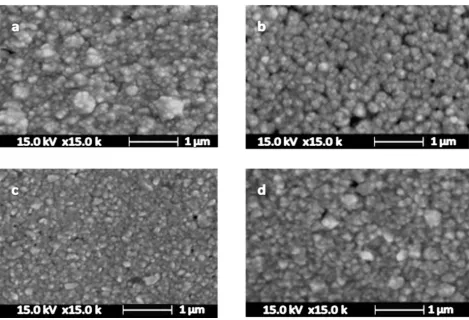
The effect of the pulse time on the properties of electroplated samples was duly investigated. In this section, the different pulse times of 0.1 s, 0.3 s, 0.5 s and 1 s were applied. Figure 4 shows the SEM images of the obtained samples at different pulse times.
[image:7.596.74.521.69.515.2]
pulse, the Au-Co nanoparticles are formed. Any variation in the number of electrons can affect the morphology and the sizes of the sample particles.
Figure 4. SEM images of samples obtained by pulse plating at different pulse time (ton) amounts, (a)
0.1 sec, (b) 0.3 sec, (c) 0.5 sec and (d) 1 sec
3.4. Optimization of pulse electrodeposition temperature
Subsequent to the optimization of the pulse parameters, the pulse current density, the relaxation time (toff), and the pulse time (ton) were 3 mA.cm-2, 1.5 s and 0.5 s respectively (at 25±2 ºC or room
temperature, in other words). Since the solution temperature can change the mechanism and kinetic of the chemical and electrochemical reactions, the temperature should be optimized to obtain a suitable morphology and optimal particle sizes. To optimize this parameter, five samples were pulse electroplated at different temperatures (5 ºC, 15 ºC, 25 ºC, 35 ºC and 45 ºC). Figure 5 shows the SEM images of the prepared samples.
[image:8.596.64.533.128.448.2]
Figure 5. SEM images of samples obtained by pulse plating at different temperature amounts, (a) 5
º
C, (b) 15 ºC, (c) 25 ºC sec, (d) 35 ºC and (e) 45 ºC
3.5. Effect of additives
However, the addition of cadmium ion to the gold-cobalt sample did not result in more suitable properties (i.e. morphology and hardness). The hardness tests on these samples showed that the samples prepared in the presence of Cd2+and Tl+ ions were 170 and 180 HV in hardness, respectively. Thus, thallium improves properties such as hardness, uniformity and brightness in hard gold coatings [38].
Figure 6. SEM images of two Au–Co samples prepared in the presence of additive (a) 40 ppm Tl+ and (b) 40 ppm Cd2+
3.7. Characterization of optimized Au-Co pulse electrodeposited layer
The optimum conditions for the pulse electrodeposition of the Au-Co alloy obtained from the optimization experiments presented in sections 3-1 to 3-5 are summarized in Table 1. The electroplated sample in the optimum conditions was characterized by EDS, XRD analysis, surface roughness measurements and Tafel plots for corrosion behavior.
Table 1. Optimum conditions for the pulse electrodeposition of Au-Co alloy
Temperature (ºC) toff (s)
ton (s)
Current density (mA.cm-2) Parameter
25 1.5
0.5 3
Optimum value
[image:10.596.67.532.180.358.2]
high cobalt content of the sample prepared in the optimized conditions, therefore, it is clear that the optimized sample shows more hardness than the sample electroplated through the dc current.
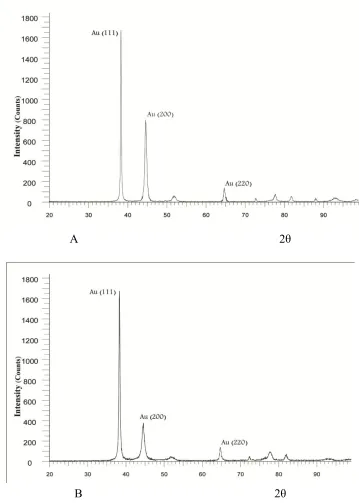
Gold is crystallized in a face-centered cubic structure where the most densely packed planes are (111) followed by (200) and then (220) [50]. According to studies conducted by Raub and Knodler [5], a high degree of orientation in the pulse-plated deposits was observed in the X-ray investigation and the Au (200) orientation in the plated deposit in the conventional dc was about 50 percent less than that of the pulsed deposit. In the present work, the pulse plated sample under optimized conditions had the highest growth rate in the orientation of the Au (111) plane. Fig.7 shows the XRD patterns.
A 2θ
B 2θ
[image:11.596.118.477.207.710.2][image:12.596.66.518.192.241.2]
Table 2 displays the mean surface roughness (Ra), the depth of surface roughness (Rz), and the maximum grain height (Rmax) of the grains of the gold alloy deposit under optimized conditions. As may be observed, as the pulse plated sample in optimum conditions is more fine-grained and has a lower vertical growth rate [51], its roughness is less than that of the conventional dc plated sample.
Table 2. Surface roughness for gold-cobalt alloy deposits
Deposition *Ra (µm) *Rz (µm) *Rmax (µm)
By conventional dc 0.182 1.04 1.38
By pulse current 0.54 0.45 0.68
*mean surface roughness Ra, surface roughness depth Rz, and the maximum grain height Rmax
[image:12.596.59.537.447.711.2]Electrochemically plated cobalt hard gold on nickel substrates is of importance in connector applications due to high corrosion resistance [52]. In this work, an electrochemical method was applied to evaluate corrosion performance. Tafel plots of the optimized pulse plated deposits and those of the conventional dc plated deposits with different amounts of cobalt (0.4% and 0.1%, respectively) were recorded in 3.5% NaCl solution in order to compare the corrosion resistances (Fig. 8). Based on the presented Tafel plots, pulse electroplating causes a reduction in the corrosion rate. This is mostly due to the reduced porosity in the pulse plated deposit which explains why the corrosion resistance is higher than that of the conventional dc deposit.
4. CONCLUSIONS
Pulse electroplating is a reliable, controllable and powerful technique to prepare a surface layer with uniform nanostructures and satisfactory hardness. In this method, the pulse height (pulse current amplitude), the relaxation time, the pulse time and the temperature of the alloy gold bath are the most effective factors in the morphology, hardness and corrosion behavior. In electroplating hard gold, thallium (I) ion can be used as a suitable additive to improve the morphology and hardness of the electroplated layer. It was further observed that the roughness of the gold alloy deposited by the pulsed current was less than that of the conventional dc plated sample.
ACKNOWLEDGEMENTS
We gratefully acknowledge the invaluable support provided by Abhar Payame Noor University Research Council.
References
1. L. P. Bicelli, B. Bozzini, C. Mele and L. D'Urzo, A Review of Nanostructural Aspects of Metal Electrodeposition, J. Electrochem. Sci., 3 (2008) 356 - 408
2. Z. Liu, M. Zheng, R. D. Hilty, A. C. West, Abstract 212, 218th ACS meeting (2010).
3. A.F. Jankowski, “Modeling Nanocrystalline Grain Growth During The Pulsed Electrodeposition of Gold-Copper” CA, United States, 2005.
4. S. D. Beattie, J. R. Dahn, J. Electrochem. Soc. 150 (2003) A894. 5. N. Masuko, T.O.a.Y.I. Electrochem. Technol. Innov. New Dev. (1996). 6. J. Cl. Puippe, N. Ibl, J. Appl. Electrochem., 10 (1980) 775.
7. M. S. Chandrasekar and M. Pushpavanam, Electrochim. Acta, 53 (2008)3313. 8. M. Antler, Plating, 60 (1972) 468.
9. C. J Raub and A. Knodler, Gold Bull. 10 (1977) 2. 10.N. Ibl, J. Puippe, H. Angerer, Surf. Technol. 6 (1978) 287. 11.J. Puippe, N. Ible, Plat. Surf. Fin. 68 (1980)68.
12.G. Devaraj, S. K. Seshadri, Plat. Surf. Fin. 83 (1996) 62.
13.A.M. Fantazi, J. Page, U. Erb, J. Appl. Electrochem. 26 (1996) 1225. 14.A.M. El-Shrerik, U. Erb, J. Page, Surf. Coat. Technol. 88 (1996) 78. 15.K. C. Chan, N. S. Qu, D. Zhu, Surf. Coat. Technol. 99 (1998) 73.
16.M. Saitou, W. Oshikawa, M. Mori, A. J. Makabe, J. Electrochem. Soc. 148 (2001) C780. 17.N. S. Qu, D. Zhu, K. C. Chan, W. N. Lei, Surf. Coat.Technol. 168 (2003) 123.
18.K. M. S. Youssef, C. C. Koch, P. S. Fedkiw, J. Electrochem. Soc. 151 (2004) C103.
19.F. H. Reid and W. Goldie, “Gold Plating Technology”, Electrochemical Publications,Ltd., Ayr, Scotland, 1974.
20.W. S. Rapson and T. Groenewald, “Gold Usage”, Academic Press, London, 1978.
21.N. N. Balashova, T. A. Smirnova, N. A. Smagunova and A. K. Yudina, Zh. Prlki. Khim. 50 (1977) 2698
22.H. Angerer And N. Ibl, J. Appl. Electrochem. 9 (1979) 219.
23.V. A. Zabluovskii, A. V. Krapironi and N. A. Kostin, Electro Khimiya 25 (1989) 1258. 24.H. U. Galgon, Feingeratctechnik 38 (1989) 353.
25.H. R. Khan, M. Baughrtner and Ch. J. Raub, Electrochem. Soc., Penninyton NJ (1987) P165. 26.H. A. Reinheirner, J. Electrochem. Soc. 121 (1974) 490.
28.F. B. Koch, Y. Okonaka, C. Wolowodiuk and D. R. Blessington lbld.67 (1980) 43. 29.S. Nakahara and Y. Okinaka, J. Electrochem. Soc128 (1981) 284.
30.S. Valizadeh, E.B. Svedberg and P. Leisner, J. Appl. Electrochem. 32 (2002) 97. 31.S. J. Hemsly, Gold Bull, 29 (1996) 19.
32.G. Bacquias, Gold Bull,15 (1982) 124. 33.Lerner et al, US Patent, 4 (1978) 076598.
34.D. Landolt and A. Ruffoni, Electrochim. Acta 33 (1988) 1281. 35.C. C. Lo, J. A. Augis, M. R. Pinnel, J. Appl. Physc. 50(1979)6887. 36.J. D. E. McIntyre and W. F. Peck Jr., J. Electrochem. Soc.123(1976)1800. 37.A.M. Weisberg and H. Kroll, US Patent 4(1978)073, 7009.
38.M. Hosseini and S. Ebrahimi, The effect of Tl(I) on the hard gold alloy electrodeposition of Au–Co from acid baths, Journal of Electroanalytical Chemistry, 645 (2010)109–114.
39.R. Duva and A. Simonian, US Patent 3 (1971) 562,120. 40.P. T. Smith and A. Fletcher, US Patent 3 (1972) 644,184. 41.H. A. Reinheimer, US Patent 3 (1974) 833,487.
42.E. Winters, US Patent 3(1975)873,428.
43.Ch. J. Raub, A. Knödler, J. Lendvay, Plat. Surf. Finish.63(1976)35. 44.H. Angerer, N. Ibl, J. Appl. Electrochem. 9 (1979) 219.
45.A.Knödler, Elecktrochem.28 (1974) 465.
46.Y. Okinaka, F. B. Koch, C. Wolowodiuk, D. R. Blessington, J. Electrochem . Soc. 125 (1978) 1745.
47.R. V. Green, T. Jones, Trans. Inst. Met. Finish. 75 (1997) 162. 48.T.A. Davies, P. Watson, Plat. Surf. Finish. 60 (1973) 1138. 49.D. L. Malm, M. J. Vasile, J. Electrochem. Soc. 120 (1973) 1484.
50.J. W. Dini, “The Materials Science of Coatings and Substrates”, Livemiore, Califorilia,1993. 51.Y. G. Li, A. Lasia, J. Appl. Electrochem. 27 (1997) 643.
52.I.Christie and B. Cameron, Gold Bull. 27 (1994) 12.