ScienceDirect
Available online at Available online at www.sciencedirect.comwww.sciencedirect.com
ScienceDirect
Procedia Manufacturing 00 (2017) 000–000www.elsevier.com/locate/procedia
* Paulo Afonso. Tel.: +351 253 510 761; fax: +351 253 604 741 E-mail address: [email protected]
2351-9789 © 2017 The Authors. Published by Elsevier B.V.
Peer-review under responsibility of the scientific committee of the Manufacturing Engineering Society International Conference 2017.
Manufacturing Engineering Society International Conference 2017, MESIC 2017, 28-30 June
2017, Vigo (Pontevedra), Spain
Costing models for capacity optimization in Industry 4.0: Trade-off
between used capacity and operational efficiency
A. Santana
a, P. Afonso
a,*, A. Zanin
b, R. Wernke
b a University of Minho, 4800-058 Guimarães, PortugalbUnochapecó, 89809-000 Chapecó, SC, Brazil
Abstract
Under the concept of "Industry 4.0", production processes will be pushed to be increasingly interconnected, information based on a real time basis and, necessarily, much more efficient. In this context, capacity optimization goes beyond the traditional aim of capacity maximization, contributing also for organization’s profitability and value. Indeed, lean management and continuous improvement approaches suggest capacity optimization instead of maximization. The study of capacity optimization and costing models is an important research topic that deserves contributions from both the practical and theoretical perspectives. This paper presents and discusses a mathematical model for capacity management based on different costing models (ABC and TDABC). A generic model has been developed and it was used to analyze idle capacity and to design strategies towards the maximization of organization’s value. The trade-off capacity maximization vs operational efficiency is highlighted and it is shown that capacity optimization might hide operational inefficiency.
© 2017 The Authors. Published by Elsevier B.V.
Peer-review under responsibility of the scientific committee of the Manufacturing Engineering Society International Conference 2017.
Keywords: Cost Models; ABC; TDABC; Capacity Management; Idle Capacity; Operational Efficiency
1. Introduction
The cost of idle capacity is a fundamental information for companies and their management of extreme importance in modern production systems. In general, it is defined as unused capacity or production potential and can be measured in several ways: tons of production, available hours of manufacturing, etc. The management of the idle capacity
Procedia Manufacturing 15 (2018) 1215–1223
2351-9789 © 2018 The Authors. Published by Elsevier B.V.
Peer-review under responsibility of the scientific committee of the 17th International Conference on Metal Forming. 10.1016/j.promfg.2018.07.366
10.1016/j.promfg.2018.07.366 2351-9789
© 2018 The Authors. Published by Elsevier B.V.
Peer-review under responsibility of the scientific committee of the 17th International Conference on Metal Forming.
Available online at www.sciencedirect.com
ScienceDirect
Procedia Manufacturing 00 (2018) 000–000www.elsevier.com/locate/procedia
2351-9789 © 2018 The Authors. Published by Elsevier B.V.
Peer-review under responsibility of the scientific committee of the 17th International Conference on Metal Forming.
17th International Conference on Metal Forming, Metal Forming 2018, 16-19 September 2018,
Toyohashi, Japan
Effects of flow forming parameters on dimensional accuracy in
Cr-Mo-V steel tubes
Jill Miscandlon
a,*, Martin Tuffs
b, Steven T. Halliday
b, Alastair Conway
aaAdvanced Forming Research Centre, Univeristy of Strathclyde, 85 Inchinnan Drive, Inchinnan, PA4 9LJ, UK bRolls-Royce plc, Derby, DE24 8BJ, UK
Abstract
Flow forming is a near-net shape forming process used to produce a range of tubular components. Advantages of the process include increased mechanical properties, grain refinement and high production rates. The cost effectiveness of the process stems from a reduction in input weight and a reduction in final machining time as compared to machine from solid routes. Careful selection of flow forming parameters, such as feed rate and spindle speed, is needed to ensure that the dimensional requirements of component design are met. The main purpose of this work was to explore the effects of machine parameters on geometrical outputs of flow formed trial parts in Cr-Mo-V steel, which is used in aerospace applications. Cr-Mo-V steel was flow formed in the annealed and the hardened and tempered conditions to assess the formability of the material across a range of input hardness. Results including inner diameter growth, formed wall thickness and material sectional hardness are presented. Forming trials were conducted at the Advanced Forming Research Centre on a WF STR600/3 flow former, which is equipped with force sensors on all three of the forming axes. The required forming loads are a significant aspect of managing tool life in an industrial setting, therefore the roller loads generated during forming have been studied. Experiments showed that there is a clear link between machine parameters and geometrical outputs. Slower feed rates and faster spindle speeds resulted in larger inner diameter growth and reduced wall thicknesses. Increased spindle speeds also caused a significant reduction in forming load. The hardness of the material was found to be proportional to the thickness reduction imposed on the trial parts in the annealed condition. Overall, it was observed that varying parameters in flow forming produced clear trends in the outputs, which can be used to predict tolerances in the design of components.
* Corresponding author. Tel.: +44 141 534 5235, Fax: +44 141 562 3387 E-mail address: [email protected]
Available online at www.sciencedirect.com
ScienceDirect
Procedia Manufacturing 00 (2018) 000–000www.elsevier.com/locate/procedia
2351-9789 © 2018 The Authors. Published by Elsevier B.V.
Peer-review under responsibility of the scientific committee of the 17th International Conference on Metal Forming.
17th International Conference on Metal Forming, Metal Forming 2018, 16-19 September 2018,
Toyohashi, Japan
Effects of flow forming parameters on dimensional accuracy in
Cr-Mo-V steel tubes
Jill Miscandlon
a,*, Martin Tuffs
b, Steven T. Halliday
b, Alastair Conway
aaAdvanced Forming Research Centre, Univeristy of Strathclyde, 85 Inchinnan Drive, Inchinnan, PA4 9LJ, UK bRolls-Royce plc, Derby, DE24 8BJ, UK
Abstract
Flow forming is a near-net shape forming process used to produce a range of tubular components. Advantages of the process include increased mechanical properties, grain refinement and high production rates. The cost effectiveness of the process stems from a reduction in input weight and a reduction in final machining time as compared to machine from solid routes. Careful selection of flow forming parameters, such as feed rate and spindle speed, is needed to ensure that the dimensional requirements of component design are met. The main purpose of this work was to explore the effects of machine parameters on geometrical outputs of flow formed trial parts in Cr-Mo-V steel, which is used in aerospace applications. Cr-Mo-V steel was flow formed in the annealed and the hardened and tempered conditions to assess the formability of the material across a range of input hardness. Results including inner diameter growth, formed wall thickness and material sectional hardness are presented. Forming trials were conducted at the Advanced Forming Research Centre on a WF STR600/3 flow former, which is equipped with force sensors on all three of the forming axes. The required forming loads are a significant aspect of managing tool life in an industrial setting, therefore the roller loads generated during forming have been studied. Experiments showed that there is a clear link between machine parameters and geometrical outputs. Slower feed rates and faster spindle speeds resulted in larger inner diameter growth and reduced wall thicknesses. Increased spindle speeds also caused a significant reduction in forming load. The hardness of the material was found to be proportional to the thickness reduction imposed on the trial parts in the annealed condition. Overall, it was observed that varying parameters in flow forming produced clear trends in the outputs, which can be used to predict tolerances in the design of components.
1216 Jill Miscandlon et al. / Procedia Manufacturing 15 (2018) 1215–1223 2 Miscandlon et al / Procedia Manufacturing 00 (2018) 000–000
© 2018 The Authors. Published by Elsevier B.V.
Peer-review under responsibility of the scientific committee of the 17th International Conference on Metal Forming.
Keywords: Flow forming; Tube spinning; Cold forming; Cr-Mo-V steel; Inner diameter growth; Sectional hardness
1.Introduction
Flow forming is a near-net shape forming process used to produce a range of tubular components. Advantages of the process include increased strength properties, grain refinement, improved material utilization, and excellent surface finish [1]. Work has previously been carried out to investigate the effects of flow forming parameters on the residual stress [2] and texture [3] of flow formed Cr-Mo-V steel, and fatigue properties in high-strength steel alloys [4]. However, understanding and controlling the accuracy of flow formed components has not been reported to the same extent, but is important to the implementation of the process into a large scale production environment.
Nomenclature
FR feed rate, mm/min
SS spindle speed, revolutions/min, RPM
2.Experimental set-up
Experiments were conducted at the Advanced Forming Research Centre (AFRC), Glasgow, UK, using Cr-Mo-V steel in the annealed and the hardened and tempered conditions. These trials were conducted as part of the Innovate UK (I-UK) funded project SAMULET II (Strategic Affordable Manufacturing in the UK through Leading Environmental Technologies). The purpose of these trials was to test various spindle speeds and feed rates to assess their effects on geometrical features, material hardness, and force required to deform the material. The experiments were carried out using Cr-Mo-V steel, with the nominal composition of the material used given in Table 1.
Table 1. Chemical composition of Cr-Mo-V steel [TATA, 2014] [5].
C Cr Mo V Si Mn Fe
0.40 3.24 0.92 0.19 0.25 0.53 Rem
The AFRC’s production scale flow former, the STR 600-3/6 shown in Fig. 1 (left), was used during the experiments. The STR 600-3/6 is a horizontal, three roller machine which can forward flow form components up to 2500 mm and reverse flow form components up to 4000 mm in length [6]. A test part, shown in Fig. 1 (right) and Fig. 2, was designed to include material reductions of 30, 55 and 65% to enable information to be gained about several different reduction rates from a single formed part. For the experimental trial, axial feed rate and spindle speed were adjusted to determine their effect on the formed part. The feed rate ranged from low to high for the annealed parts, and low to medium for the hardened parts, with the feed rate adjusted in increments of 10 mm/min per part. The hardened parts were not formed to the highest feed rates of the annealed parts because harder material requires to be formed slower than softer material. The spindle speed range had an upper limit of 500 RPM for the annealed parts, and 400 RPM for the hardened parts.
Jill Miscandlon et al. / Procedia Manufacturing 15 (2018) 1215–1223 1217
"Miscandlon et al" / Procedia Manufacturing 00 (2018) 000–000 3
[image:3.544.56.389.73.261.2][image:3.544.56.504.322.386.2]
Fig. 1. AFRC's STR 600-3/6 horizontal flow former (left), and flow formed test geometry (right).
Fig. 2. Schematic of flow formed test component
To assess the effect of feed rate and spindle speed on the work piece three experiments were conducted per material condition: the first two experiments kept the spindle speed constant whilst adjusting the feed rate, whereas the third experiment maintained a constant feed rate and varied the spindle speed. Each experimental trial is detailed in Table 2. It can be seen that hardening and tempering was carried out to produce hardness values in the range 543-575HV to investigate the formability of material at the upper limit for Cr-Mo-V steel.
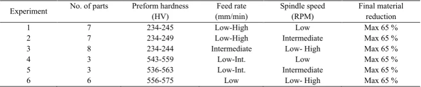
Table 2. Experimental set-up for Cr-Mo-V steel parts.
Experiment No. of parts Preform hardness (HV) (mm/min) Feed rate Spindle speed (RPM) Final material reduction
1 7 234-245 Low-High Low Max 65 %
2 7 234-249 Low-High Intermediate Max 65 %
3 8 234-244 Intermediate Low- High Max 65 %
4 3 543-559 Low-Int. Low Max 65 %
5 3 536-563 Low-Int. Intermediate Max 65 %
6 6 556-575 Low Low- High Max 65 %
3.Results and discussion
[image:3.544.63.482.507.594.2]1218 Jill Miscandlon et al. / Procedia Manufacturing 15 (2018) 1215–1223 4 Miscandlon et al / Procedia Manufacturing 00 (2018) 000–000
3.1.Dimensional accuracy
An important factor in flow forming being cost competitive is to produce parts that negate the need for final machining in the bore. This requires the inner diameters produced along the length of a part are understood and that the design calls out appropriate tolerances. A major aim in flow forming is to induce predominantly axial material flow, which contributes to the elongation of the preform, and restrict tangential flow. In practice tangential flow will occur during flow forming which manifests itself as inner diameter growth. Variables that affect inner diameter growth include material, reduction rates, and machine parameters. Increased levels of inner diameter growth have a number of disadvantages which include a reduction in the achievable straightness [7]. A practical aspect of inner diameter growth is that the manufacturer will size the preform inner diameter so that the nominal inner diameter of the part is achieved after the growth that occurs during flow forming. Also, the final part tolerances have to account for the differences in inner diameter growth that occurs, for example, between regions of the component that are reduced in thickness the most and least during flow forming.
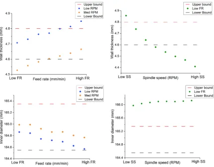
In order to aid the understanding of achievable tolerances on flow formed parts, several geometrical features were measured after forming including inner diameter and wall thickness. Representational graphs are shown for the thinnest wall section for each of the features, which corresponds to a material reduction of 65%. In Fig. 3 the blue points represent Experiment 1, the orange points represent Experiment 2, and the green points represent Experiment 3 from Table 2. From Fig. 3 it can be seen that the feed rate and spindle speed have differing effects on both the wall thickness and inner diameter. As the feed rate is increased, the output wall thickness of the formed parts also increased, however as the spindle speed was increased, the wall thickness decreased. Slower feed rates result in a thinner formed section, which is consistent with the material having been worked for a longer time by the forming rollers. In a similar manner, a faster spindle RPM also resulted in the material being worked more times per minute, hence more material compression and a thinner formed section.
The hardness range for the annealed material is within a narrow range, which has reduced the potential for variation in the outputs between parts, and clear trends have emerged. For these trials, an increase in feed rate resulted in smaller component inner diameters. The difference in recorded inner diameter from the low and high reed rate was approximately 0.4 mm, which is a significant in comparison with a typical tolerance of ±0.4 mm applicable to many industrial applications. An increase in the spindle speed resulted in a slight increase in the formed inner diameter, approximately 0.1 mm difference from low to high spindle speed. From these initial experiments the feed rate has a greater impact than spindle speed when considering inner diameter growth. The choice of a low fixed feed rate for evaluating the effect of the spindle speed on inner diameter growth may not have been optimal since a low feed rate also appeared to result in a higher output diameter, and additional trials could be designed to include a full Design of Experiments to fully understand the interactions between feed rate and spindle speed.
Jill Miscandlon et al. / Procedia Manufacturing 15 (2018) 1215–1223 1219
[image:5.544.60.492.70.406.2]"Miscandlon et al" / Procedia Manufacturing 00 (2018) 000–000 5
Fig. 3. Measured wall thickness (top) for variable feed rate (left) and variable spindle speed (right), and measured inner diameter (bottom) for variable feed rate (left) and variable spindle speed (right).
3.2.Material hardness
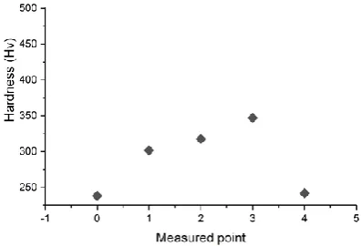
After the parts were formed, hardness values were recorded on the surface at 5 different lateral positions. Position 0 represents the non-flow formed section closest to the flange; positions 2, 3, and 4 represent formed sections with low, intermediate, and high percentage of material reduction, respectively; and position 4 represents the non-flow formed section at the end of the component.
1220 Jill Miscandlon et al. / Procedia Manufacturing 15 (2018) 1215–1223 6 Miscandlon et al / Procedia Manufacturing 00 (2018) 000–000
Fig. 4. Typical hardness values for parts flow formed in annealed condition.
3.3.Force evolution
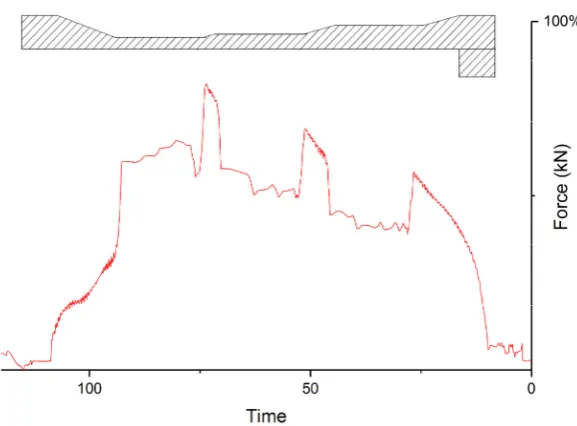
Roller forces give important information regarding the resistance of the material during the flow forming process. Such information can be related to studies on tool life, machine requirements and the forming operation. Previous papers have considered the forces required to deform material during the spinning process [8], but very little information is available on the forming loads required for flow forming. For the annealed preforms, the geometry was formed in a single pass and so the force traces consist of a single cycle of data, as represented in Fig. 5.
For the hardened preforms, the forces recorded were close to the machine limits so it was decided to form the geometry in two passes which gave two distinct regions on the force trace. Typical force traces of the third and final forming roller for the annealed and hardened parts are shown in Fig. 5 and Fig. 6, respectively. Approximately 10 seconds into the force trace, the rollers contact the parts and the load increases until a peak is reached. This increase in load corresponds to the rollers compressing the material from the initial wall thickness to a 30% reduction. Once this reduction is reached the rollers are programmed to form a straight wall section of constant thickness and the force remains relatively constant with a slight reduction over time. The next peak is recorded as the rollers reduce thickness to 55% reduction from the original wall thickness. The peak force drops off again as the rollers form a straight wall section, then the highest peak is recorded as the material is deformed to 65% reduction. The peaks on the graphs are always recorded during the transitions between sections of different thicknesses, with higher material reductions creating higher peak forces.
Jill Miscandlon et al. / Procedia Manufacturing 15 (2018) 1215–1223 1221
[image:7.544.129.418.68.281.2]"Miscandlon et al" / Procedia Manufacturing 00 (2018) 000–000 7
[image:7.544.138.410.340.524.2]Fig. 5. Typical force trace for annealed part with schematic of formed part overlaid to show relationship between wall thickness reduction and peak force.
Fig. 6. Typical force trace for hardened part, with maximum force for annealed parts recorded at 83% of maximum force for hardened parts.
1222 Jill Miscandlon et al. / Procedia Manufacturing 15 (2018) 1215–1223 8 Miscandlon et al / Procedia Manufacturing 00 (2018) 000–000
[image:8.544.149.395.75.463.2]
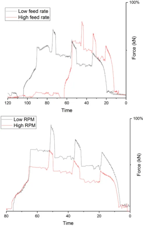
Fig. 7. Effect of feed rate (top) and spindle speed (bottom) on forces generated during forming.
4. Conclusions
Jill Miscandlon et al. / Procedia Manufacturing 15 (2018) 1215–1223 1223
[image:9.544.87.459.94.172.2]"Miscandlon et al" / Procedia Manufacturing 00 (2018) 000–000 9
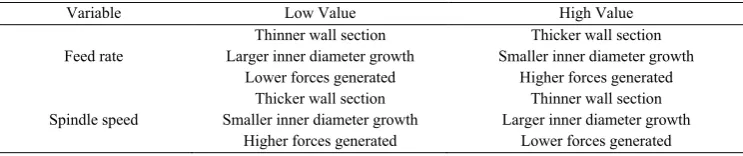
Table 3. Summary of high level trends.
Variable Low Value High Value
Feed rate Larger inner diameter growth Thinner wall section Lower forces generated
Thicker wall section Smaller inner diameter growth
Higher forces generated
Spindle speed Smaller inner diameter growth Thicker wall section Higher forces generated
Thinner wall section Larger inner diameter growth
Lower forces generated
The feed rate and spindle speed have a clear effect on inner diameter, wall thickness, and load requirements. Wall thickness is the simplest of these features to control and can be readily adjusted by altering the final roller input depth. Optimising the parameter set, for example minimising inner diameter growth whilst maintaining wall thickness, for a particular material can be achieved by understanding the interaction between variables through experiments such as those presented in this paper. Overall it was observed that varying parameters in flow forming produced clear trends in the outputs, which can be used to confidently predict tolerances for near net shape component design.
Acknowledgements
The authors would like to acknowledge the funding provided by Innovate UK for the research project SAMULET II (Strategic Affordable Manufacturing in the UK through Leading Environmental Technologies). Acknowledgements are also given to the Advanced Forming Research Centre, University of Strathclyde, Glasgow and Manufacturing Technology - Materials Processing Technology Team, Rolls-Royce, Derby.
References
[1] M. Chen, R. Hsu, K. Fuh, An analysis of force distribution in shear spinning of cone, International Journal of Mechanical Sciences, 47 (2005) 902–921.
[2] D. Tsivoulas, J.Q.D. Fonseca, M. Tuffs, M. Preussa, Effects of flow forming parameters on the development of residual stresses in Cr–Mo–V steel tubes, Materials Science & Engineering: A, 624 (2015) 193–202.
[3] D. Tsivoulasa, J.Q.D. Fonseca, M. Tuffs, M. Preuss, Measurement and modelling of textures in flow formed Cr-Mo-V steel tubes, Materials Science & Engineering: A, 685 (2017) 7–18.
[4] S. Notargiacomo, F. Placidi, A. Reynaert, M. Duchet, F. Valente, M. Santos, I. Perez, EUR 23726 - The influence of flow-forming process parameters on the fatigue behaviour of high-strength steel wheels for the automotive industry, European commission, Research Fund for Coal and Steel series, ISBN 978-92-79-10858-7.
[5] TATA Steel UK Ltd., Cr-Mo-V steel raw billet, June 2014 [6] AFRC equipment brochure,
https://www.strath.ac.uk/media/1newwebsite/centres/advancedformingresearchcentre/AFRC_equipment_brochure.pdf. [7] M. Runge, D.H. Pollitt, Spinning and Flow Forming. Leifeld Metal Spinning 1993: Verlag moderne industrie AG.