City, University of London Institutional Repository
Citation
:
Mergos, P.E. (2017). Contribution to sustainable seismic design of reinforced concrete members through embodied CO2 emissions optimization. Structural Concrete, doi: 10.1002/suco.201700064This is the accepted version of the paper.
This version of the publication may differ from the final published
version.
Permanent repository link:
http://openaccess.city.ac.uk/18081/Link to published version
:
http://dx.doi.org/10.1002/suco.201700064Copyright and reuse:
City Research Online aims to make research
outputs of City, University of London available to a wider audience.
Copyright and Moral Rights remain with the author(s) and/or copyright
holders. URLs from City Research Online may be freely distributed and
linked to.
Contribution to sustainable seismic design of reinforced concrete
members through embodied CO
2emissions optimization
Panagiotis E. Mergos *
Research Centre for Civil Engineering Structures, Department of Civil Engineering, City,
University of London, London EC1V 0HB, United Kingdom
Abstract. The embodied CO2 emissions of reinforced concrete (RC) structures can be significantly
reduced by structural optimization that maximizes structural efficiency. Previous studies dealing with
design of RC structures for minimum CO2 emissions do not address seismic design provisions. This is
the case despite the fact that in many countries around the world, including most of the top-10
countries in CO2 emissions from cement production, RC structures have to be designed against
earthquake hazard. To fill a part of this gap, this study, using exhaustive search, examines optimum
designs of RC beam and column members for minimum embodied CO2 emissions according to
Eurocode-8 for all ductility classes and compares them with optimum designs based on material cost.
It is shown that seismic designs for minimum CO2 footprint lead to less CO2 emissions but are more
expensive than minimum cost designs. Their differences strongly depend on the assumed values of the
environmental impact of reinforcing steel and concrete materials. Furthermore, it is concluded that
seismic design for high ductility classes can drive to significant reductions in embodied CO2 emissions.
Keywords: Sustainable, environmental, embodied, CO2 emissions, optimization, seismic design,
reinforced concrete, Eurocodes
Running Head: Sustainable seismic design of concrete members
* Corresponding author. Panagiotis E. Mergos, Lecturer in Structural Engineering, Research Centre for Civil Engineering
Structures, City, University of London, London, EC1V 0HB, UK.
1 Introduction
Sustainable development is defined as meeting the needs of the present without compromising
the ability of future generations to meet their own needs. To meet this aspiration, strong actions
are required to support the three diverse and sometimes conflicting pillars of sustainability:
environmental, economic and social [1].
Climate change is one of the most important threats to sustainable development in the 21st
century. It is expected to slow down economic growth, impact human health and increase risks
from climate-related natural hazards [2]. Anthropogenic greenhouse gas (GHG) emissions
have been the dominant cause of the observed climate change [2]. The built environment is
one of the main contributors of GHG emissions [3].
Reinforced concrete (RC) is ubiquitous in the built environment. Its environmental impact
consists of embodied emissions of reinforcing steel and concrete. Embodied emissions of
reinforcing steel are related to the energy used to melt scrap metal and reform it [1]. Embodied
emissions of concrete are attributed mostly to cement production. Cement emissions are
generated by fuel combustion and carbon oxidation during clinker production. It is estimated
that cement is responsible for roughly 8% of global CO2 emissions) [4].
Clearly, embodied CO2 emissions of reinforced concrete can be reduced by recycling or using
novel materials such as low carbon cements and clinker substitutes [1]. In addition, structural
optimization methodologies can be applied to maximize material efficiency and minimize the
environmental impact of RC structures.
A significant number of research studies focus on optimum design of RC structures for
minimum environmental impacts. Yeo & Gabbai [5] investigated optimum designs of RC
beams for minimum embodied energy. They concluded that optimization for embodied energy
results in decreases on the order of 10% in embodied energy at the expense of an increase on
reduction depends strongly on the cost ratio of steel reinforcement to concrete. Medeiros and
Kripka [6] examined optimum designs of RC columns under uniaxial bending and compression
loads for different environmental assessment parameters including CO2 emissions. They found
that designs for minimum CO2 emissions produce 1% less CO2 footprints and they are 1%
more expensive than minimum cost-based designs. Furthermore, studies [7-9] comparing
optimum designs of RC frames for minimum CO2 footprint and construction cost report that
the former lead to 4-15% less CO2 emissions than then latter. They also conclude that the actual
reductions depend on the cost and environmental impact ratios of reinforcing steel to concrete
materials [9].
All previous studies do not consider seismic design of RC structures. However, in many
countries around the globe, including most of the top-10 countries in CO2 emissions from
cement production (e.g. India, Iran, Turkey, Japan) [4], RC structures need to be designed
against earthquake hazard. Optimum seismic design of RC structures has been the focus of
several research studies especially the last two decades. An overview to structural seismic
design optimization frameworks can be found in Fragiadakis and Lagaros [10]. Early efforts
to optimise earthquake resistant structures were based on traditional seismic design
approaches. More recent studies investigate optimum performance-based seismic design
(PBSD) methodologies that provide better control of structural damage [11-14]. The author
[15] developed optimum seismic designs of RC frames according to traditional [16] and PBSD
methodologies [17]. It is found that PBSD provides always better damage control and it is
significantly less expensive in regions of low to moderate seismicity. However, it is
accompanied by significant computational cost that it could undermine the optimization
procedure.
All previous optimum seismic design studies set construction or life-cycle costs as design
objectives. Indeed, the environmental impact of RC structures designed for seismic resistance
the assessment of the life-cycle environmental impact of RC buildings accounting also for the
emissions produced for repairing RC members after damaging earthquakes. Tapia and Padgett
[19] developed a multi-objective optimization framework for retrofit of bridges under natural
hazards, including earthquakes, where life-cycle cost and environmental impact are set as
design objectives. However, an existing steel bridge is used as case study.
It can be concluded from the previous discussion that optimum seismic design of RC structures
for minimum embodied environmental impact has very little been explored. To fill a part of
this gap, this study develops seismic designs of RC beam and column members for minimum
cradle to site CO2 emissions and compares them with optimum designs based on material cost.
The aim is to investigate good practices for minimizing embodied CO2 emissions in seismic
design of RC members and examine the trade-offs between cost and environmental impact of
seismically designed RC members. In this manner, the environmental and economic pillars of
sustainability in the context of seismic design of RC members are properly addressed.
Furthermore, the developed framework can be extended to deal explicitly with the social
requirement of sustainable design by using appropriate methods to assess the social impact of
RC members [20].
2 Optimum design of reinforced concrete members according to Eurocodes
2.1 Optimization problem formulation and solution algorithm
A single-objective optimization problem with discrete design variables is generally formulated
as:
Subject to: 𝑔𝑗(𝒙) ≤ 0, 𝑗 = 1 𝑡𝑜 𝑚 (1)
Where:
𝒙 = (𝑥1, 𝑥2, … , 𝑥𝑛)
𝑥𝑖 ∈ 𝐷𝑖 = (𝑑𝑖1, 𝑑𝑖2, … , 𝑑𝑖𝑘𝑖) , 𝑖 = 1 𝑡𝑜 𝑛
In this problem, Ftot(x) represents the objective function of the optimization problem. The
vector x is the design solution and contains n number of independent design variables xi (i=1
to n). Design variables xi take values from discrete sets of values Di=(di1, di2, …, diki), where
dip (p=1 to ki) is the p-th possible discrete value of design variable xi and ki is the number of
allowable discrete values of xi. Furthermore, the solution should be subject to m number of
constraints gj(x)≤0 (j=1 to m). In the subsequent sections, the objective function, design
variables and design constraints in the context of the optimum seismic design of RC members
are specified in detail.
Different algorithms exist to solve the afore-described optimization problem. These can be
divided in two categories: gradient-based and metaheuristic such as Genetic Algorithms (GA),
Particle Swarm Optimization (PSO) and many others [21]. Alternatively, exhaustive search
can be employed that examines all possible combinations of design variables and finds the
combination that satisfies all design constraints and minimizes the objective function. Clearly,
this is the least efficient method in terms of computational cost. Nevertheless, exhaustive
search is adopted in this study because it is guaranteed to track global optima and it is
computationally affordable for small scale optimization problems.
2.2 Objective function
In optimization of RC members, typically, the objective function Ftot(x) is set to be the total
minimization of the total embodied CO2 emissions Etot(x). In both cases, the objective function
is taken as the sum of the corresponding contributions of concrete Fc(x), steel Fs(x) and
formwork Ff(x). Hence, it is written as follows:
𝐹𝑡𝑜𝑡(𝒙) = 𝐹𝑐(𝒙) + 𝐹𝑠(𝒙) + 𝐹𝑓(𝒙) → 𝐹𝑡𝑜𝑡(𝒙) = 𝑉𝑐(𝒙) · 𝐹𝑐𝑜+ 𝑚𝑠(𝒙) · 𝐹𝑠𝑜+ 𝐴𝑓(𝒙) · 𝐹𝑓𝑜 (2)
In Eq. (2), Vc (m3) is the concrete volume, ms (kg) the mass of steel reinforcement and Af
(m2) the area of the formwork. Fco, Fso and Ffo are the unit prices of the materials. If the material
unit economic costs (expressed in Euros per material unit quantities) are used as unit prices
(see columns 2-3 of Table 1), then Eq. (2) yields the total economic cost (i.e. Ftot(x)=Ctot(x)).
Alternatively, if the material unit environmental impacts (expressed in kgCO2 per material unit
quantities) are used (see columns 4-7 of Table 1), then Eq. (2) calculates the total embodied
CO2 emissions (i.e. Ftot(x)=Etot(x)). Furthermore, Fs(x) can be taken as the sum of the
contributions of longitudinal Fsl(x) and transversal Fsw(x) steel reinforcement.
Table 1 presents the unit prices adopted in this study for the economic cost and CO2
emissions. The economic values are based on the Hellenic Ministry of Public Works [22]. The
unit environmental impact values of concrete and steel are taken from [23]. This study reports
typical cradle to site embodied CO2 emissions and the range (low to high) of their possible
values considering different material production practices. The value of Efo is taken from [7].
Table 1: Material unit costs and environmental impacts
Material Economic
Unit Cost
Units Environmental Unit Impact Units
Low Typical High
(1) (2) (3) (4) (5) (6) (7)
Concrete C25/30 101.0 (€/m3) 142.0 228.0 319.0 (CO
2Kg/m3)
Formwork 15.7 (€/m2) 8.9 for columns; 3.1 for beams (CO
2Kg/m2)
2.3 Design parameters and variables
In optimization problems, the input data are divided in design parameters that keep constant
values and design variables that change during the optimization solution. Herein, design
parameters are the RC members’ material properties, length L, concrete cover and end forces
as shown in Fig. 1. For simplicity and to focus on seismic effects, antisymmetric member end
forces and no element distributed loads are assumed in this study.
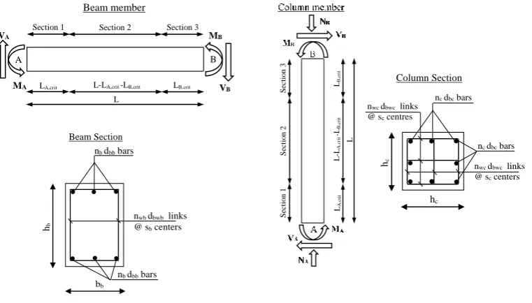
Furthermore, design variables are the cross-sectional characteristics shown again in Fig. 1.
Rectangular beam sections and square column sections are examined in this study. Beam
section design variables (Fig. 1a) are the height hb and width bb, the diameter dbb and number
of main bars nb at the top and the bottom (assumed the same due to antisymmetric loading
conditions), the diameter dbwb, spacing sb and number of legs nwb of transverse reinforcement
parallel to beam section height.
Square column section design variables (Fig. 1b) are the height (and width) hc, the diameter
dbc and number nc of main bars per side, assumed herein the same for all column section sides
for simplicity, the diameter dbwc, spacing sc and number of legs nwc of transverse reinforcement
assumed again the same in both column section directions for simplification purposes.
In addition, it is assumed that the design variables take values from discrete values sets in
accordance with construction practice. Section dimensions hc,bc, hb, bb take values multiples
of 50mm starting from 300mm. Numbers of main bars nc, nb,and legs of shear reinforcement
nwc and nwb take any integer value greater than one. Transverse reinforcement spacing sc and/or
sb take values between 80mm and 300m with a step of 20mm. Longitudinal bar diameters dbc,
dbb take values from (12, 14, 16, 18, 20, 25)mm and transversal bar diameters dbwc, and dbwb
Generally, three different section properties per RC member are used. Two for the member
critical end regions and one section for the rest part of the member. However, due to the
assumed antisymmetric response, the same design variables for the two end sections are used.
Furthermore, for simplicity reasons, it is assumed that the end and intermediate sections have
the same design variables apart from the spacing of the transverse reinforcement. The latter is
taken different to account for the more demanding detailing and seismic design requirements
in the end regions of RC members. In total, 8 independent design variables for beams and 7
variables for columns are used in this study.
Fig. 1: Design variables: a) column members; b) beam members
2.4 Design constraints
Design constraints are defined herein in accordance with the requirements of Eurocode-2
(EC2) [24] and Eurocode-8 (EC8) [16]. It is recalled that seismic design to EC8 can be
performed either without provisions for energy dissipation and ductility (Ductility Class Low – DCL) or with provisions for energy dissipation and ductility (Ductility Classes Medium and
LA,crit LB,crit
A B
L-LA,crit -LB,crit
L
Section 1 Section 2 Section 3
MA
MB
Beam member
VB
VA
nb dbb bars
hb
nb dbb bars
nwb dbwb links
@ sb centers
bb Beam Section LA ,c ri t LB ,c ri t L -L A ,c ri t -LB ,c ri t L S ec ti o n 1 S ec ti o n 2 S ec ti o n 3 hc hc
nc dbc bars
nwc dbwc links
@ sc centers
nc dbc bars
nwc dbwc links
@ sc centres
[image:9.595.100.481.292.509.2]High – DCM and DCH). DCM and DCH allow for smaller seismic loads compared to DCL,
but require more demanding rules for increasing ductility capacities.
Generally, structural design constraints gj(x) can be classified into Engineering Demand
Parameter (EDP) and Structural Design Parameter (SDP) constraints. The first category
represents the requirement that EDPs (i.e. forces, displacements, rotations, drifts) remain
below a capacity value EDPcap. In this study, EDPs are the internal forces at member ends.
End moments MA and MB (Fig. 1) are treated as known (design parameters). For DCL, shear
forces are calculated by equilibrium using end moments MA and MB. For DCM and DCH, the
capacity design shear forces are used in accordance with EC8 provisions to preclude brittle
shear failures. Corresponding capacities EDPcap are calculated by using characteristic material
strengths divided by partial safety factors equal to γc=1.50 for concrete and γs=1.15 for
reinforcing steel and using standard EC8 procedures. For bending moments of column
members, moment capacities are calculated for the axial load demand under examination.
SDPs are parameters related to the detailing of structural design solutions. SDPs can either
be design variables themselves (e.g. cross-sectional dimensions, steel bar diameters) or simple
functions of design variables like the volumetric ratios of steel reinforcement. Two cases of
SDP constraints are possible. In the first case, a SDP should be smaller than or equal to a
maximum permissible value SDPmax. In the second case, a SDP should be greater than or equal
to a minimum permissible value SDPmin. In this study, all member SDP constraints reflecting
detailing provisions of both EC2 and EC8 are taken into consideration. A detailed description
of these constraints can be found in [15].
It is noted that consideration of the design constraints is straightforward in the framework
of the exhaustive search optimization algorithm used in this study. More specifically, the
design solutions that do not satisfy all design constraints are branded as unfeasible and are
3 Numerical examples
This section presents numerical applications of the optimum seismic design methodology
of RC members described above. One beam and one column member are examined. In both
cases, concrete class C25/30 with characteristic strength fck=25MPa and reinforcing steel
B500c with characteristic strength fyk=500MPa for the longitudinal and transversal
reinforcement are used. The concrete cover is 0.03m. The beam member has length of L=5m
and it is subjected to antisymmetric end moments with magnitude Msd=300kNm. The column
member has length of L=3m and it is subjected to antisymmetric end moments Msd=500kN
and compressive axial load Nsd=500kN. Shear forces are calculated according to §2.4. The RC
members are designed according to EC8 for all ductility classes. The cost of concrete C25/30
and steel B500c are taken from Table 1. The environmental impacts are taken from the same
table following the typical scenario for both materials. Exhaustive search is used to find the
optimum solutions as described in §2.1.
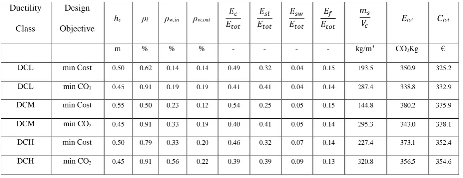
Tables 2 and 3 present the characteristics of the optimum design solutions of the beam and
column RC members designed for all ductility classes either for minimum cost or for minimum
environmental impact. Apart from cross-sectional dimensions, the longitudinal reinforcement
volumetric ratio per side ρl, the volumetric ratio of transverse steel parallel to the shear force
ρw inside and outside the critical end regions, the material contributions to environmental
impact and the total environmental impact and cost are presented.
Observing the properties of the optimum solutions, a number of conclusions can be
extracted. It can be seen that sectional dimensions are smaller for the minimum CO2 emissions
with respect to the minimum cost solutions. The opposite is the case for the longitudinal
reinforcement ratios. As a result, the environmental impact contributions of concrete and
framework are smaller and the contribution of longitudinal steel higher for the CO2 based
concrete to steel is higher than the respective cost ratio. Therefore, it is less efficient to use
concrete in terms of environmental impact with respect to economic cost. This conclusion is
also verified by the fact that the steel mass to concrete volume ms/Vc ratio, used widely in
construction industry to quantify the amount of steel in concrete, is significantly higher in the
case of minimum CO2 solutions.
It is also shown that the CO2 based solutions lead to savings in total CO2 emissions but are
more expensive than the minimum cost solutions. However, the differences are rather small.
If rCO2 is defined as the ratio of CO2 emissions of the minimum cost designs over the emissions
of the minimum CO2 designs then it is found that rCO2 ranges between 1.01 and 1.11 for both
RC members and all ductility classes. This effectively means that the optimum cost solutions
generate 1-11% more CO2 emissions than the CO2 based solutions. Similarly, if rcost is the ratio
of the cost of the minimum CO2 designs with respect to the cost of the minimum cost designs
then it is obtained that rcost ranges between 1.01 and 1.05. This means that the minimum CO2
designs are 1-5% more expensive than the minimum cost design solutions.
It is also evident that the volumetric ratios of the transverse reinforcement in the critical
end regions increase as the ductility level increases. As a result, the environmental impact of
transverse reinforcement is higher in the case of DCM and DCH with respect to DCL driving
to higher total environmental impacts of these two ductility classes for the same Msd values.
However, the relative contribution of transverse reinforcement to the total environmental
impact is rather small (2-9%) and the total environmental impacts of the different ductility
[image:12.595.72.555.702.786.2]classes are very close.
Table 2: Optimum beam solutions characteristics
Ductility
Class
Design
Objective
hb bb ρl ρw,in ρw,out
𝐸𝑐 𝐸𝑡𝑜𝑡 𝐸𝑠𝑙 𝐸𝑡𝑜𝑡 𝐸𝑠𝑤 𝐸𝑡𝑜𝑡 𝐸𝑓 𝐸𝑡𝑜𝑡 𝑚𝑠
𝑉𝑐 Etot Ctot
m m % % % - - - - kg/m3 CO
2Kg €
DCL min CO2 0.45 0.30 1.49 0.11 0.11 0.48 0.43 0.02 0.07 245.8 322.0 363.4
DCM min Cost 0.55 0.30 0.92 0.28 0.11 0.57 0.32 0.03 0.08 159.8 329.7 357.9
DCM min CO2 0.40 0.30 1.90 0.33 0.13 0.42 0.48 0.03 0.07 316.3 324.2 373.6
DCH min Cost 0.55 0.30 0.92 0.28 0.11 0.57 0.31 0.04 0.08 161.7 331.0 359.5
[image:13.595.71.539.211.391.2]DCH min CO2 0.40 0.30 1.90 0.42 0.15 0.42 0.48 0.04 0.07 322.3 327.4 377.4
Table 3: Optimum square column solutions characteristics
Ductility
Class
Design
Objective
hc ρl ρw,in ρw,out
𝐸𝑐 𝐸𝑡𝑜𝑡 𝐸𝑠𝑙 𝐸𝑡𝑜𝑡 𝐸𝑠𝑤 𝐸𝑡𝑜𝑡 𝐸𝑓 𝐸𝑡𝑜𝑡 𝑚𝑠
𝑉𝑐 Etot Ctot
m % % % - - - - kg/m3 CO
2Kg €
DCL min Cost 0.50 0.62 0.14 0.14 0.49 0.32 0.04 0.15 193.5 350.9 325.2
DCL min CO2 0.45 0.91 0.19 0.19 0.41 0.41 0.04 0.14 287.4 338.8 332.9
DCM min Cost 0.55 0.50 0.23 0.12 0.54 0.25 0.05 0.15 144.8 380.2 335.9
DCM min CO2 0.45 0.91 0.33 0.19 0.40 0.41 0.05 0.14 295.3 343.0 338.1
DCH min Cost 0.50 0.79 0.33 0.20 0.46 0.32 0.07 0.14 227.4 373.1 352.4
DCH min CO2 0.45 0.91 0.56 0.22 0.39 0.39 0.09 0.13 320.8 356.5 354.6
4 Parametric study
This section examines the effects of different design parameters on the optimum seismic
design solutions of RC members. More particularly, the effects of Msd and the material unit
costs and environmental impacts are investigated. The numerical examples presented in
section §3 serve as the basis of the parametric studies of this section.
4.1 Design bending moment Msd
This section investigates the effects of Msd on the optimum beam and column seismic design
solutions. The following Msd values Msd=100, 200, 300, 400 and 500kNm for the beam and
Msd=100, 300, 500, 700 and 900kNm for the column RC members are examined. All other
As illustrated in Fig. 2, the rcost and rCO2 ratios vary slightly with Msd. rcost varies between 1
and 1.05 and rCO2 between 1 and 1.11 for both the beam and column designs. These variations
do not seem to follow a specific trend and they should be attributed to the discrete nature of
the design variables adopted in this study. Interestingly, for the minimum Msd values, all ratios
are equal to unity. This is the case because the optimum cost and CO2 designs are the same as
both are governed by the minimum detailing requirements.
Regarding the minimum embodied CO2 emissions, it can be seen that they increase sharply
with Msd. The rate of emissions increase slightly decreases as Msd increases. For the same Msd
values, the DCH solutions produce the highest and the DCL the lowest CO2 emissions. This
could be attributed to the higher transverse reinforcement requirements of the former optimum
designs. However, the differences between the ductility classes are almost negligible because
transverse reinforcement does not contribute significantly to the total CO2 emissions. Taking
into consideration the fact that Msd values are importantly reduced when designing for higher
ductility classes (in the order of 2-4 times), it can be concluded that seismic design for higher
ductility classes may lead to important savings in CO2 emissions.
When CO2 emissions are normalized to the product Msd·L, the normalized values in
(kgCO2/kNm2) decrease as Msd increases. Furthermore, the normalized values tend to stabilize
for high Msd values. This drives to the conclusion that designs for smaller Msd values are less
efficient in terms of environmental impact per unit seismic design moment. This is especially
the case for Msd values close to zero where minimum detailing requirements govern the design
solutions.
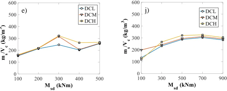
Regarding the ratio ms/Vc of the minimum CO2 solutions, it increases for small but it
becomes almost constant for higher Msd values. Generally, the DCH solutions demonstrated
f) a)
g) b)
i) d)
Fig. 2: Variation of optimum solution properties with Msd for: a-e) beam; f-j) column RC members
4.2 CO2 emissions of reinforcing steel and concrete materials
To investigate the influence of the unit environmental impacts of concrete and reinforcing
steel on the properties of the optimum solutions, the ratio R is used in this study [5]. R is
defined as the ratio of the CO2 footprint of 100kg of reinforcement steel to the CO2 footprint
of concrete per m3. Next, three different scenarios are examined with regards to the
combinations of environmental impacts of C25/30 concrete and reinforcing steel based on the
values presented in Table 1. Typical concrete – typical steel impact (R=0.38); high concrete –
low steel impact (R=0.13) and low concrete - high steel impact (R=1.25). Furthermore, to
consider the fact that values of reinforcement steel CO2 emissions even smaller than the low
limit given in [23] have been reported in literature [9, 25] a scenario with high concrete CO2
impact and zero reinforcing steel CO2 footprint (R=0) is also examined herein. The latest
scenario is used to envelope all scenarios with R<0.13. The results presented in the following
are based on the numerical examples of section §3, where only the unit environmental impacts
of concrete and steel are altered.
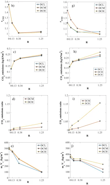
As shown in Fig. 3, the ratios rcost and rCO2 vary significantly with R. rcost varies between 1
and 1.24 and rCO2 between 1 and 1.55 for both the beam and column designs. The highest j)
[image:16.595.98.480.72.225.2]values are observed for R=0, followed by R=0.13 (high concrete - low steel impact scenario).
For example, for R=0.13, the minimum cost column design for DCM produces 27% more
emissions than the respective minimum CO2 design. This difference is rather important and
should be taken into consideration in optimum seismic design of RC members. It is also
interesting to note that rcost and rCO2 vary sharply between R=0 and R=0.38 but they change
slightly between R=0.38 and R=1.25. Similar conclusions hold for all ductility classes.
Regarding the minimum embodied CO2 emissions, it can be deducted that they become
maximum in the R=1.25 (high concrete – low steel impact) scenario. In all cases, DCH designs
produce the most CO2 emissions followed by DCM. It is interesting to note that the differences
in CO2 emissions between ductility classes increase as R increases. This becomes more evident
in Figs (5d, 5i) that present the ratios of CO2 emissions of ductility classes DCM and DCH to
DCL for the beam and column RC members respectively. These ratios increase as R increases.
This is attributed to the fact that DCM and DCH require more transverse reinforcement and
the environmental impact of steel increases as R increases.
Furthermore, the ratios ms/Vc of the minimum CO2 solutions decrease sharply as R
increases. This is justified by the fact that the concrete becomes less and steel more expensive
in terms of environmental impact as R increases. Therefore, more concrete and less steel are
preferred in the optimum solutions as R increases.
Fig. 3: Variation of optimum solution properties with R for: a-e) beam; f-j) column RC members
g) b)
h) c)
i) d)
[image:18.595.100.478.71.705.2]5 Summary and Conclusions
Reinforced concrete members are major contributors of CO2 emissions. Their
environmental impact can be reduced by recycling or using novel materials. Alternatively,
structural optimization can be employed that maximizes material efficiency and minimizes
embodied CO2 emissions.
Previous studies dealing with structural design of RC structures for minimum CO2
emissions do not address seismic design. This study examines optimum seismic designs of RC
beam and column members for minimum embodied CO2 emissions in accordance with EC8
provisions for all ductility classes.
For the typical concrete and reinforcing steel environmental impact scenarios, it is found
that the optimum CO2 solutions have smaller cross-sectional dimensions and larger
longitudinal steel reinforcement and ms/Vc ratios than the minimum cost designs. It is also
shown that the CO2 based solutions lead to additional reductions in total CO2 emissions but
are more expensive than the minimum cost solutions for the same seismic forces. Nevertheless,
the differences are rather small and the ratios rcost and rCO2 range roughly between 1.0 and 1.1.
This effectively means that the optimum CO2 designs perform well in terms of economic cost
and vice versa. The previous conclusion is not the case, however, for the high concrete – low
reinforcing steel impact scenario, where rcost may take values up to 1.25 and rCO2 up to 1.55.
Comparing the minimum CO2 designs of different ductility classes, it is observed that they
differ mainly in the transverse reinforcement requirements in the critical end regions, which
increase as the level of ductility class increases. Therefore, DCM and DCH designs produce
more CO2 emissions than DCL for the same seismic moments. However, the contribution of
transverse reinforcement to the total CO2 emissions is rather small. Hence, the differences in
total CO2 emissions between ductility classes are minor. Considering that Msd values are
sharply increase with Msd values, it can be concluded that seismic design for high ductility may
drive to important reductions in embodied CO2 emissions.
Regarding the ms/Vc ratios of the optimum CO2 design solutions, they decrease sharply with
the R ratio because the relative cost of steel increases. On the other hand, they are not very
sensitive to the applied Msd values. More particularly, they increase with Msd for small Msd
values but they tend to stabilize for higher Msd values.
All previous conclusions hold for individual RC beams and column members. Unarguably,
future research is required to examine whether these conclusions can be extended to the seismic
design of complete RC frames and, more generally, different types of RC structures.
References
[1] Georgopoulos, C. & Minson, A. (2014). Sustainable concrete solutions. John Wiley and
Sons, Oxford.
[2] Intergovernmental panel on climate change (IPCC) (2014). Climate change 2014:
Synthesis report. Technical Report, Geneva, Switzerland.
[3] Green Construction Board (2016). Low carbon routemap for the UK built environment.
Technical Report, London, UK.
[4] Olivier, J.G.J. et al. (2015). Trends in global CO2 emissions: 2015 Report. Joint Research
Centre, Hague, Netherlands.
[5] Yeo, D. & Gabbai, R. (2011). Sustainable design of reinforced concrete structures through
embodied energy optimization. Energy and Buildings, 43, 2028-2033.
[6] Medeiros, G. & Kripka, M. (2014). Optimization of reinforced concrete columns according
to different environmental impact assessment parameters. Engineering Structures, 59,
185-194.
[7] Paya-Zaforteza, I., Yepes, V., Hospitaler, A., Gonzalez-Vidosa, F. (2009). CO2
-optimization of reinforced concrete frames by simulated annealing. Engineering Structures,
[8] Camp, C., Huq, F. (2013). CO2 and cost optimization of reinforced concrete frames using
a big bang-big crunch algorithm. Engineering Structures, 48, 363-372.
[9] Yeo, D. & Potra, F. (2015). Sustainable design of reinforced concrete structures through
CO2 emission optimization. ASCE Journal of Structural Engineering, 141, B4014002, 1:7.
[10] Fragiadakis, M., Lagaros, N.D. (2011). An overview to structural seismic design
optimisation frameworks. Computers and Structures, 89, 1155-1165.
[11] Ganzerli, S., Pantelides, C.P., Reaveley, L.D. (2000). Performance-based design using
structural optimization. Earthquake Engineering and Structural Dynamics, 29, 1677-1690.
[12] Chan, C.M., Zou, X.K. (2004). Elastic and inelastic drift performance optimization for
reinforced concrete buildings under earthquake loads. Earthquake Engineering and Structural
Dynamics, 33, 929–950.
[13] Lagaros, N.D. & Papadrakakis, M. (2007). Seismic design of RC structures: A critical
assessment in the framework of multi-objective optimization. Earthquake Engineering and
Structural Dynamics, 36, 1623-1639.
[14] Fragiadakis, M., Papadrakakis, M. (2008). Performance-based optimum seismic design
of reinforced concrete structures. Earthquake Engineering and Structural Dynamics, 37,
825-844.
[15] Mergos, P.E. (2016). Optimum seismic design of reinforced concrete frames according
to Eurocode 8 and fib Model Code 2010. Earthquake Engineering and Structural Dynamics,
46, 1181-1201.
[16] CEN: EN 1998-1. Eurocode 8. Design of structures for earthquake resistance. Part 1:
General rules, seismic actions and rules for buildings. Comité Europeén de Normalisation,
Brussels; 2004.
[18] Hossain, K., Gencturk, B. (2014). Life-cycle environmental impact assessment of RC
buildings subjected to natural hazards. ASCE Journal of Architectural Engineering,
A4014001, 1-12.
[19] Tapia, C. & Padgett, J.E. (2016). Multi-objective optimisation of bridge retrofit and
post-event repair selection to enhance sustainability. Structure and Infrastructure Engineering, 12,
93-107.
[20] Pons, O., Fuente, A. (2013). Integrated sustainability assessment method applied to
structural concrete columns. Construction and Building Materials, 49, 882-893.
[21] Lagaros, N.D. (2013). A general purpose real-world structural design optimization
computing platform. Journal of Structural and Multidisciplinary Optimization, 49,
1047-1066.
[22] Hellenic Ministry of Public Works (2013), Readjustment and completion of invoices of
public works. Technical Report, Athens, Greece.
[23] Kaethner, S.C., Burridge, J.A. (2012). Embodied CO2 of structural frames. Structural
Engineer, 90, 33-40.
[24] CEN: EN 1992-1-1. Eurocode 2. Design of concrete structures. Part 1-1: General rules
and rules for buildings. Comité Europeén de Normalisation, Brussels; 2000.
[25] Alcorn, A. (2003). Embodied energy and CO2 coefficients for NZ building materials.