A Preliminary
Evaluation
of a Hydro-cast Trans-femoral Socket, a Proof of
Concept
Arjan Buis
1*, Mojtaba Kamyab
2, Susan Hillman
3, Kevin Murray
1and Anthony McGarry
1 1Department of Biomedical Engineering, University of Strathclyde, Glasgow, Scotland, UK2Department of Orthotics and Prosthetics, Tehran University of Medical Sciences, Tehran
3Astley Ainslie Hospital, Anderson Gait Analysis Laboratory, Edinburgh, Scotland, UK
*Corresponding author: Buis A, Department of Biomedical Engineering, University of Strathclyde, Glasgow, Scotland, UK, Tel: 0044 (0)141 548 4716; E-mail: [email protected]
Rec date: November 09, 2016; Acc date: April 18, 2017; Pub date: April 24, 2017
Copyright: © 2017 Buis A, et al. This is an open-access article distributed under the terms of the Creative Commons Attribution License, which permits unrestricted use, distribution, and reproduction in any medium, provided the original author and source are credited.
Citation: Buis A, Kamyab M, Hillman S, Murray K, McGarry A (2017) A preliminary evaluation of a hydro-cast trans-femoral socket, a proof of concept. Pro Ort Open J 1: 7.
Abstract
This study reports on a research project that has utilised, for the firsttime, a Hydro-casting (HC) technique to create a
prosthetic socket for a person with trans-femoral
amputation. Outcome measurements of the HC socket were compared with a socket and prosthesis produced by
conventional ischial containment (IC) technique. Comparisons were based on differences in (a) stump-socket interface pressures during gait, (b) whole body gait kinetics
and kinematics (c) femoral movement within the stump
tissuesrelative to the socket during gait.
These observations provided a snapshot of the biomechanical environment of the stump and socket interface and assess the feasibility of using these outcome measurements to highlight differences between the two socket designs.
This study demonstrated that it is feasible to use the HC approach to produce a prosthesis that is acceptable to both user and clinician. Results showed similarities between interface pressures, kinetic and kinematic data for both socket designs. The use of ultrasound to detect femoral
motion identified that the conventional design paradigm, claiming to stabilise the motion of the femur, may not actually achieve this goal. Additional research is required with larger population of people with a trans-femoral
amputation to assess the long term impact of this novel approach.
Keywords:
Prosthetics; Amputation; X-ray; Abduction/ Adduction; Flexion/ExtensionAbbreviations/Definitions
Prosthesis, prosthetic device: externally applied device used to replace wholly, or in part, an absent or deficient limb segment
Trans-tibial: Amputation through the limb below the knee and transecting both the tibia and fibula.
Trans-femoral: Amputation performed at a level above the knee joint.
Hydro-casting (HC): A technique of applying controlled pressure to the tissues of an amputation stump and casting
material to fashion a socket design shape using quasi-hydrostatic pressure.
Ischial Containment (IC): A design of trans-femoral prosthesis socket employing lateral socket wall pressure and enclosure of the ischium to stabilise the movement of the femur during gait and thereby enhance usability.
Introduction
In contemporary prostheticpractice there is clinical consensus that the ‘quality’ of the socket providing the coupling between the tissues of the residual limb and the structure of the prosthesis is vital to the overall success of the prosthetic
replacement [1-10]. However, there is limited evidence available about what actually determines the quality of fit and few reliable measurements have been taken of the biomechanical environment that could constitute a high quality result. This is perhaps not surprising as the stump socket interface brings together engineered materials, formed into a complex shape, with living tissue that has non-linear, time dependent and highly individual mechanical properties [11,12].
Trans-femoral amputation accounts for over 40% of all new
amputations in the UK [13]. The Ischial Containment (IC) socket design is advocated at this level. The fundamental concept of the IC design is that greater control of femoral abduction during
prosthetic mid stance phase, (and hence improved function),
can be obtained by a particular shaping of the socket that “locks” around the ischium and loads the lateral aspect of the femur to effectively stabilise it [14-16]. Ischial containment sockets have however, continually evolved since their inception
State of the art IC prosthetic sockets are designed and hand
crafted on a bespoke basis. Procedures are highly individual, based on the tacit knowledge of a prosthetist and strongly
influenced by personal experience, skill and beliefs [12]. If the socket design process is inconsistent this will also cause challenges in positioning the socket appropriately for
ambulation (alignment) [17]. Without doubt, failure to create a repeatable standardised socket design will compromise
prostheticrehabilitation [8,18].
The creation of a socket through controlled pressure-casting
has been advocated in many publications and is now used widely in trans-tibial, but not in trans-femoral prosthetics
[19,20]. Pressure casting, using water as a pressurising medium, has been shown to be more repeatable [21], and reduce errors by the prosthetist that may occur during plaster cast
modification [18]. Klasson and Buis [12], believed that improved
function and less tissue stress in weight bearing would be achieved using Hydro-Casting (HC). Furthermore, they stated that traditional plaster room modification could be eliminated using this technique. Kristinsson [14] argued that the most
effective socket should rely on a hydrostatic principle for weight transfer and that through application of a controlled pressurised
casting technique a ‘near’ hydrostatic equilibrium point could be achieved. A socket which is of good fit, is considered to be one that reaches equilibrium with little vertical movement i.e. pistoning. To reduce the flow of all soft tissue structures, the socket should be shaped under a uniform pressure condition. In principle, when the skeleton attempts to translate into the socket, the tissues are therefore ideally positioned, and the socket shaped such that vertical movement is minimised.
Pressure casting deforms the softtissue, under full load, such that hypothetically the stiffest path principle is achieved and internal shear stresses are minimized [12]. This is thought to be advantageous as the purpose of the socket is to provide a mechanical connection between skeleton and socket, utilizing
the soft tissue as interdependent coupling elements. It is also expected that the stiffer this coupling, the more stability is realised, and therefore improved control of the prosthesis may be achieved.
The aim of this study is to assess the feasibility of shape capture of the trans-femoral residual limb shape using a HC technique, and to investigate the dynamic mechanical environment at the stump-socket interface and within the deeper structures of the stump. The overall impact of this approach on the gait of a person with trans-femoral amputation
will also be examined. Outcomes from the novel HC technique will be compared with a socket and prosthesis produced by the established conventional ischial containment hand-casting
technique.
Methodology
A 36 year old female volunteer from a Scottish based charitable prosthetic user support organisation, the Murray
foundation, was recruited to this study. She had undergone a TF
amputation in 1992 as a result of a giant cell tumor in the right
tibia. Her current prescription which had not changed for over
10 years, included a flexible ischial containment socket with seal-in liner and a one –way valve, Otto Bock C-leg and dynamic plus foot. Ethical approval was granted by the Ethics Committee
of the University of Strathclyde.
A crossover study design allowed direct comparison between the two interventions. However, it was not realistic to adopt a double-blind test as the socket design concepts were considerably different in human/device interaction and socket brim levels compromising unbiased user feedback. Two
prosthetic sockets were manufactured. Both used the same silicone liner with pin and shuttle lock suspension and utilised
the same knee and foot components. An identical copy of the
existing IC design of socket was made and a transparent acrylic
plastic socket manufactured to replace the socket of the existing
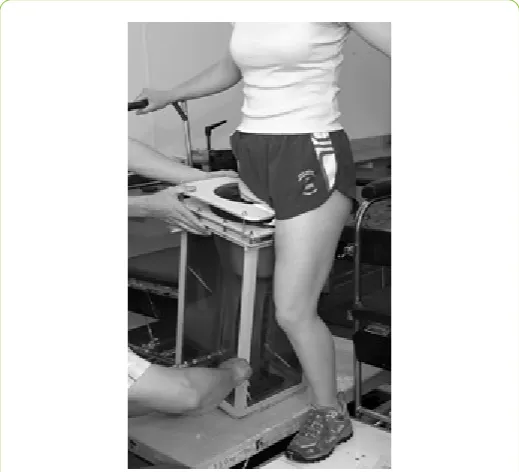
prosthesis, with the aim to maintain component characteristics. Additionally, a HC socket was manufactured (Figure 1). The experimental HC device consisted of an open top tank with an internal thin sleeve fixed at the proximal brim and was secured to the bottom of the tank. This created a sealed water tank with a collapsible tunnel, which acted as a barrier between the loading medium (water) and cast limb. Additionally, the tunnel design allowed the soft tissue to be stretched distally (slack
[image:2.595.305.565.400.636.2]elimination) by means of a lanyard threaded through the hollow bolt at the distal end of the tank.
Figure 1: Experimental Hydro-casting.
A silicone interface liner was applied to the residual limb and a lanyard was attached to the distal adaptor of the liner and threaded through the flexible tunnel and hollow bolt previously described. Plaster of Paris (POP) bandage was loosely applied covering the whole residual limb. No attempt was made by the
prosthetist to smooth or shape the plaster once applied. The
mechanism between limb and latex sleeve, preventing
“ballooning” of the sleeve when pressurized.
Subsequently, the tank was filled with water until the patient
was able to transfer full body weight to the amputated site. This meant that the soft tissues were fully loaded by a uniform pressure induced by the subject’s own body weight. Slack
elimination was achieved by the application of a load to the soft tissue until no more visible elongation took place (typically between 20 and 30 Newton). The subject remained in situuntil
the POP cured, (approximately 4 minutes). No modifications
were performed on the positive plaster model and a transparent
plastic check socket was manufactured. The socket was placed on the same components that were used for the IC socket
investigation. Since no known alignment criteria were available for this socket design the socket was dynamically aligned until
the user and two clinicians were satisfied.
Outcomes for comparison were based on differences in: • Dynamic stump-socket interface pressures during gait, • Motion analysis (kinetics and kinematics) and
• Femoral movement within the stump tissuesrelative to the socket during gait.
These observations provide an insight of the biomechanical environment of the stump and socket interface and highlight any
differences between the two socket designs.
Dynamic residual limb-socket interface
pressures during gait
The pressure measurement system selected to monitor and record the interface pressure between the residual limb and
prosthetic socket was a validated 6-channel F-Scan system™ (Tekscan, Boston, MA, USA). The authors were aware of the
limitations of the pressure measurement system employed [22-24]. It is commonly accepted that the advantages of the Tekscan™ transducers are thickness, size, sensitivity, and
resolution and frequency response. Disadvantages such as hysteresis, drift and temperature sensitivity have also been reported [23-27]. However, by adopting a strict protocol to
precondition, equilibrate and calibrate the sensor arrays in situ
before use, it was possible to minimize the variation and inaccuracy of data recordings [22]. Four channels were designated to the prosthetic socket (sensor array type 9811. The socket transducer arrays were glued inside each of the transparent check sockets according a predetermined reference grid, allowing over 80% surface coverage.
Gait
kinetics
and
kinematics
Introduction
A state-of-the-art 3D Vicon™ motion capture system, equipped with twelve infra-red cameras and four Kistler™ force
platforms were used to collect comparative full body kinematic (motion) and kinetic (force and acceleration) of upper and lower body gait data from the subject. This will allow any potential
compensatory gait effects (E.g. limping and gapping) of each socket concept to be examined in detail.
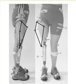
[image:3.595.305.563.212.496.2]The Vicon Plug-in-Gait marker placement protocol was used which allowed the detailed examination of the effect of each socket philosophy on gait. In addition, supplementary markers were placed on the socket (Figure 2) with the aim to establish an independent reference grid. This configuration, in theory, would allow possible socket rotation, gapping and pistoning relative to the pelvis markers to be monitored.
Figure 2: Supplementary markers and reference grid.
Kinematic and kinetic data were collected as the subject walked along the laboratory walkway. Only trials in which the subject made a clean force platform strike with at least one foot were retained for analysis (n=6).
Femoral movement within the stump
tissues
relative
to the socket during gait
The biomechanical interaction between the prosthetic socket and the residual limb determines the quality of the fit and this included skeletal movement within the socket [12]. The understanding of this interaction and the development of
quantitative measures to predict the quality of fit of the socket are quintessential for optimal socket design [12]. Various methods have been utilised to determine skeletal movement in both trans-tibial and trans-femoral sockets ranging from X-ray,
magnetic resonance imaging (MRI) and ultrasound [28-33]. Of those technologies ultrasound is the most practical
technology considering cost (MRI) and ionising radiation
socket. Inaccuracies due to equipment limitations and those due to human error were identified and quantified. Ranges of
flexion/extension and abduction/adduction of the residual femur within the socket during gait were estimated with a
cumulative level of error of <1°.
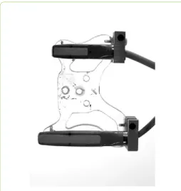
For this study, a Shimadzu™ SDU-400 diagnostic ultrasound scanner and two linear transducers with different scanning areas (40 mm and 80 mm) both operating in the 5 MHz frequency range were utilized.
The transducers were mounted on a custom designed and manufactured holder and spaced 120 mm apart. This created an array arrangement that is able to monitor skeletal movement on two level planes.
[image:4.595.306.564.123.386.2]Furthermore, this assembly allowed the array to be transferred between the sockets without losing their spatial configuration(Figure 3).
Figure 3: Ultrasound sensor array.
Two rectangular windows were cut in the lateral aspect of the experimental sockets allowing the transducers to be in direct contact with the silicone liner to ensure appropriate acoustic
transmission i.e. no air pockets/layers.
Ultrasound gel was directly applied to the residual limb over the transducer contact area before the silicone liner was applied. Afterapplication of the liner the prosthesis was donned as normal and the sensor array, smeared with gel, was mounted on the socket (Figure 4).
The data acquisition system consisted of: ultrasound equipment with external video output, a stationary video camera with a field of view in the sagittal plane of the subject and a video mixer/recorder to generate a digital split screen recording of the ultrasound image and visual gait data. Femoral
[image:4.595.30.285.307.576.2]movement data was recorded as the subject walked along a walkway in the gait lab.
Figure 4: Transducer array in situ.
Results
Dynamic stump-socket interface pressures during
gait
Results indicate that sockets produced by both conventional
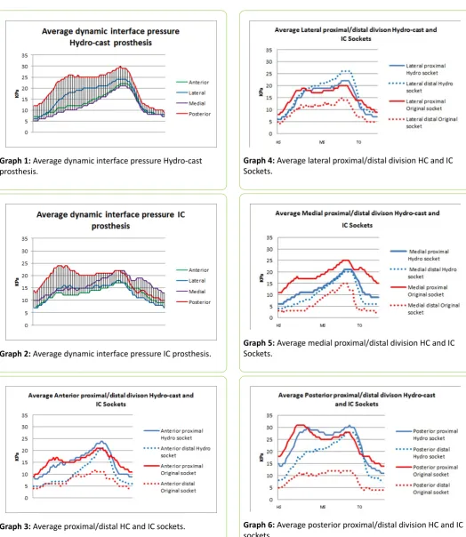
IC and HC techniques, generated similar dynamic interface pressures (Graphs 1 and 2).
It must be noted that the average pressure of the four sensor arrays for the HC system are more uniform during toe-off/ double support compared with that of the IC system. Although the HC socket exhibited elevated pressures on average, no
significant clinical differences, <50 kPa [22], were detected. When the sockets were divided into proximal and distal regions, (Graphs 3-6), it was noted that the difference in regional average pressure for the HC socket was closer than for the IC socket.
Gait
kinematics
and
kinetics
No marked differences were observed between the two
Graph 1: Average dynamic interface pressure Hydro-cast prosthesis.
Graph 2: Average dynamic interface pressure IC prosthesis.
Graph 3: Average proximal/distal HC and IC sockets.
Graph 4: Average lateral proximal/distal division HC and IC Sockets.
Graph 5: Average medial proximal/distal division HC and IC Sockets.
[image:5.595.35.560.86.691.2]Graph 6: Average posterior proximal/distal division HC and IC sockets.
Table 1: Temporal and Distance Parameters.
Stride Length (m) 1.35 0.024 1.38 0.018 1.35 0.028 1.39 0.042
Cadence (steps/min) 116 1.63 116 1.81 117 2.05 115 1.17
Double Support (s) 0.24 0.0087 0.23 0.020 0.23 0.0075 0.24 0.019
Single Support (s) 0.46 0.010 0.44 0.0082 0.34 0.014 0.37 0.014
Step Length (m) 0.63 0.019 0.65 0.019 0.72 0.012 0.74 0.021
Step Time (s) 0.47 0.019 0.48 0.012 0.57 0.015 0.56 0.0082
Step Width (m) 0.21 0.017 0.16 0.014 0.21 0.016 0.17 0.012
The most notable difference observed in the lower body was that the right (prosthetic) side peak knee flexion was slightly but consistently decreased by between 5 and 10 degrees with the HC socket prosthesis compared with the IC socket prosthesis. It appears that with the IC socket the subject ensures ground clearance with increased knee flexion, whereas with the HC socket it is via increased vaulting.
The range of relative movement between the pelvis markers and lateral socket wall (gapping) was reduced with the prosthesis with the HC socket by around 10-15 mm as illustrated in Graph 7. This shows the changing lateral distance between two markers, one placed on the lateral, most proximal aspect of the socket, and one placed directly above on the subject’s pelvis. This corresponds to ‘gapping’, a conditiontraditionally assessed by observation. The horizontal scale illustrates one gait cycle from initial contact to initial contact and the vertical scale is millimeters. Data collected from the IC socket is shown as a series of blues traces and data from the HC socket are green. The results show less gapping with the HC socket.
Graph 7: Gapping.
The pistoning data, illustrated in Graph 8, for the HC socket showed a decreased range of motion compared to the IC socket.
The IC socket result displayed an initial decrease in the longitudinal distance between the socket displacement markers in loading, as would be expected. During mid and terminal stance and pre-swing however, this motion then reversed and the distance increased.
With the HC socket the distance between the markers decreased through stance.
Graph 8: Pistoning.
The rotational data as shown in Graph 9 showed that the
rotational stability was increased within the prosthesis
incorporating the HC socket.
Graph 9:Rotational stability.
Summary
• Speed slightly higher with the IC socket, but it was noted that the subject’s speed increased as she became more accustomed to the HC socket.
• Stride length slightly longer with the IC socket, affected via increased step length bilaterally.
• Cadence and double support time much the same for both Sockets.
• Step width increased with the HC socket.
• Reduced gapping, pistoning and rotation measured within the HC socket.
Femoral Movement
Relative
to the Socket
During Gait
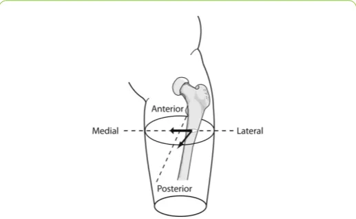
Two linear ultrasound sensors were fixed to the lateral wall of both socket designs. Motion of the femur relative to the socket was tracked as the subject walked at a self-selected walking speed. Results show that the dynamic motion of the femur within the IC prosthetic system progressed from the lateral socket aspect at heel strike towards the medial socket aspect
[image:7.595.31.290.335.494.2](Figure 5 bold arrow). The dynamic femoral motion found in the HC prosthetic system indicated that the femoral progression started in the antero-lateral aspect and moved to the posterior-lateral aspect of the socket. (Figure 5 thin arrow) Moreover the range of movement was considerably less as compared with the IC prosthetic system.
Figure 5: Femoral movement relative to the socket during gait.
Discussion
The dynamic interface pressure measurement results indicate that prostheses produced by both casting techniques, generated similar average dynamic interface pressures. That the average pressure was elevated for the prosthesis with the HC socket came as no surprise and might be directly related to the nature of casting under a full soft tissue loading condition. It is recognised that there might be an element of load transfer through the ischium (not measured) that could explain lower pressures in the IC socket. Similar pressure distributionfindings
between hands-on and hands- offcasting concepts, although for
trans-tibial prostheses, have been reported by Dumbleton et al. [4].
When pressure results were divided into proximal and distal regions, it was noted that the average pressures were more uniform for the prosthesis with the HC socket. Additionally, it was found that the proximal pressure on each of the sensor
locations for the IC socket was higher than for the distal regions. To draw conclusions from interface pressure data alone is not
possible from this sample size. It is also difficult to distinguish if the recorded pressure data is a result of axial loading, couples and moments, a direct result of alignment or socket shape related issues. Furthermore, there is growing consensus amongst researchers that interface shear force may be an even greater determinant of user comfort and socket fit.
[14,15,24,34-44]
It was anticipated that although gait differences between socket designs were likely to be subtle, differences may be clinically significant. Therefore, it was necessary to develop gait analysis methods specific to the trans-femoral level of
amputation that would be sufficiently sensitive to the changes introduced by the intervention. To date, kinematic and kinetic
data have not been widely used to assess the socket-stump interface in amputees. This study started this process by measuring motion at the body device boundary: a process analogous to the prosthetists observational check of gapping and pistoning during gait as indicators of socket fit integrity. The gapping and pistoning were calculated as the absolute distance between two ‘socket displacement markers, one placed on the lateral proximal aspect of the socket and the other superior to it on the subject. The directions of these displacements were aligned with the thigh embedded axis system, with one axis between the hip joint centre and knee joint centre and one parallel with the knee flexion axis.
It was found that the range of socket gapping motion was reduced with the prosthesis with the HC socket. This finding is important as it implies a reduced soft tissue compliance “coupling stiffness” between the weight bearing structure, the skeleton and socket as predicted by the stiffest path principle [6,12]. The femoral stability data also support this hypothesis by
indicating minimal femoral motion in the medio-lateral direction
with the HC socket, as compared with the IC socket which demonstrated a greater range of motion with the femur progressing in the lateral-medial direction. The HC socket however showed more femoral motion in the anterio-posterio
direction. Further investigation with a larger sample size is necessary to validate these results. The confounding factor of
differing trim-lines must also be taken into consideration.
This pilot study on one subject has suggested that gait
differences with the investigated sockets are likely to be subtle. This does not necessarily mean that the differences are clinically
insignificant. It will therefore be necessary to develop and validate gait analysis methods specific to trans-femoral amputees which are sufficiently sensitive to the changes introduced by the intervention. As well as including standard gait parameters such as joint angle and moment, and ground
reaction force data, this will also involve less commonly used measures, for example, joint center displacement, segment
orientation and center of pressure progression.
To date, kinematic and kinetic data have not been widely used to assess the socket-stump interface in amputees, so it is proposed also to investigate methods by which this may be done. This pilot study started this process by measuring motion
at the body device boundary: a process analogous to the
Alternative approaches to the kinematic and kinetic
assessment of interfacial stability should also be investigated. It has been suggested by Seliktar [45] for example, that the fore-aft horizontal component of the ground reaction force can be used for this. It is therefore proposed to investigate the feasibility of this and other measures further.
The successful completion of this will not only play a vital role in the evaluation of the socket design philosophy, but could
ultimately contribute to the wider field of clinical gait analysis in lower-limb prosthetic subjects by enhancing the objectivity of assessment in clinical prosthetics.
The range of relative movement between the pelvis and lateral socket wall (gapping) was reduced with the prosthesis with the HC socket by around 10-15 mm. This may however be because the IC socket extended more superiorly than the HC socket implying that a greater range of motion was possible with this condition. The pistoning data for the HC socket also showed a decreased range of motion by around 50 mm compared to the IC socket. The patterns of pistoning motion for the two sockets are surprisingly opposite. The IC socket shows an initial decrease in the longitudinal distance between the socket displacement markers in loading, as would be expected. During mid and terminal stance and pre-swing however, this motion then reversed and the distance increased. With the HC socket the distance between the markers decreased through stance. This
finding could be explained by the coronal plane rotation of the socket on the residual limb, which also gives rise to the fact that gapping increased the longitudinal distance between the markers more than the compression in stance was decreasing it.
Adherents of the most widely used design philosophies for trans-femoral sockets have described how their approaches
influence or control the motion of the femur relative to the stump tissues and the socket. [4,5] Although a case study, results indicate the possibility that the HC socket may offer improved medio-lateral stability compared to the IC socket as used by the test subject. This is also highlighted by Kahle [46] who removed
different socket elements systematically in a case study examining trans-femoral socket design. This paper reported that femoral stability, one of the claimed benefits of the IC approach, was not influenced by the so-called bony-lock element of the design.
Conclusions
This study has demonstrated the feasibility of the HC approach, without modification, at trans-femoral level of
amputation. Interface pressures using the HC method appeared to generate similar levels to the conventional IC approach during gait. Shear force at the interface could not be measured for this study, and would be an essential addition to continued work. Body motion and kinetic data showed similarities between limbs produced with the two designs. Differences in gapping and pistoning between the designs may be significant and should ideally be monitored in sync with pressure and shear data in a larger trial. The use of ultrasound to detect femoral motion identified that the IC design concept, which claims to stabilize the motion of the femur, may not be as effective as predicted in
individual sockets due to the handcrafted method of manufacture. The motion of the femur within the tissues and the socket would be expected to provide a good indication of the quality of socket fit and yet this has never been exhaustively
researched.
References
1. Klute GK, Berge JS, Orendurff MS, Williams RM, Czerniecki JM (2006) Prosthetic intervention effects on activity of lower-extremity amputees. Arch Phys Med Rehabil 877: 717-722. 2. Datta D, Harris I, Heller B, Howitt J, Martin R (2004) Gait cost and
timeimplications for changing from PTB to ICEX sockets. Prosthet Othot Int 28: 115-120.
3. Portnoy S, van Haare J, Geers RP, Kristal A, Siev-Ner I, et al. (2010)
Real-time subject-specific analyses of dynamic internal tissue
loads in the residual limb of transtibial amputees. Med Eng Phys 32: 312-323.
4. Dumbleton T, Buis AW, McFadyen A, McHugh BF, McKay G, et al. (2009) Dynamic interface pressure distributions of two transtibial prosthetic socket concepts. J Rehabil Res Dev 46: 405-415. 5. Almassi F, Mousavi B, Masumi M, Souroush MR, Honari G, et al.
(2009) Skin disorders associated with bilateral lower extremity
amputation. Pak J Biol Sci 12: 1381-1384.
6. Bo Klasson (1995) Appreciation of prosthetic socket fitting from basic engineering principles. Glasgow (GB): National Centre for Training and Education in Prosthetics and Orthotics pp: 26. 7. Buis AW, Condon B, Brennan D, McHugh B, Hadley D (2006)
Magnetic resonance imaging technology in transtibial socket research: a pilot study. J Rehabil Res Dev 43: 883-890.
8. Johansson S, Oberg T (1998) Accuracy and precision of volumetric
determinations using two commercial CAD systems for
prosthetics: a technical note. J Rehab Res Develop 35: 27-33. 9. Hagberg K, Branemark R (2001) Consequences of non-vascular
trans-femoral amputation: A survey of quality of life, prosthetic
use and problems. Prosthet Orthot Int 25: 186-194.
10. Gailey R, Allen K, Castles J, Kucharik J, Roeder M (2008) Review of secondary physical conditions associated with lower-limb
amputation and long-term prosthesis use. J Rehabil Res Dev 45: 15-29.
11. Sanders JE, Goldstein BS (2001) Collagen fibril diameters increase and fibril densities decrease in skin subjected to repetitive
compressive and shear stresses. J Biomec 34: 1581-1587.
12. Klasson B (2006) Prosthetic Socket Fit Implications of basic engineering principles. Advanced prosthetic science University of Strathclyde Glasgow p: 56.
13. http://www.nasdab.co.uk.
14. Long IA (1985) Normal shape normal alignment (NSNA) AK prosthesis. Clin Prosthet Orthot 9: 9-14.
15. Ortiz RM (2007) MAS Design for trans-femoral prostheses. Orthop Tech 10-13.
16. Sabolich J (1985) Contoured adducted trochanteric-controlled alignment method (CATCAM) Introduction and basic principles. Clin Prosthet Orthot 9: 15-26.
18. Buis AW, Blair A, Convery P, Sockalingam S, McHugh B (2003) Pilot study: Data-capturing consistency of two trans-tibial casting
concepts, using a manikin stump model: a comparison between the hands-on PTB and hands-off ICECAST compact® concepts. Prosthet Orthot Int 27: 100-106.
19. Kristinsson O (1993) The ICEROSS concept: A discussion of a philosophy. ProstheticsOrthotics Int 17: 49-55.
20. Redhead RG (1979) Total surface bearing self suspending above-knee sockets. ProstheticsOrthotics Int 3: 126-136.
21. Convery P, Buis AW (1999) Socket/stump interface dynamic pressure distributions recorded during the prosthetic stance phase of gait of a trans-tibial amputee wearing a hydrocast socket. Prosthet Orthot Int 23: 107-112.
22. Buis AW, Convery P (1997) Calibration problems encountered while monitoring stump/socket interface pressures with force sensing resistors: techniques adopted to minimise inaccuracies. Prosthet Othot Int 21: 179-182.
23. Polliack AA, Sieh RC, Craig DD, Landsberger S, McNeil DR, et al. (2000) Scientific validation of two commercial pressure sensor systems for prosthetic socket fit. Prosthet Othot Int 24: 63-73. 24. Sanders JE (1995) Interface mechanics in external prosthetics:
review of interface stress measurement techniques. Medical Biolog Eng Comp 33: 509-16.
25. Mak AF, Zhang M, Boone DA (2001) State-of-the-art research in lower-limb prosthetic biomechanics-socket interface: A review. J Rehab Res Develop 38: 161-74.
26. Woodburn J, Helliwell P (1997) Observations on the F-Scan in-shoe pressure measuring system. Clinical biomechanics, 1997. 12: S16. 27. Woodburn J, Helliwell PS (1996) Observations on the F-Scan
in-shoe pressure measuring system. Clin Biomec 11: 301-304. 28. Convery P, Murray KD (2000) Ultrasound study of the motion of
the residual femur within a trans-femoral socket during gait. Prosthet Othot Int 24: 226-232.
29. Douglas TS, Solomonidis SE, Sandham WA, Spence WD (2002) Ultrasound imaging in lower limb prosthetics. IEEE Transactions
Neural Systems Rehabil Eng 10: 11-21.
30. Douglas TS, Solomonidis SE, Sandham WA, Spence WD (2002) Ultrasound image matching using genetic algorithms. Med Biol Eng Comput 40: 168-172.
31. Murray KD, Convery P (2000) The calibration of ultrasound transducers used to monitor motion of the residual femur within a trans-femoral socket during gait. Prosthet Othot Int 24: 55-62. 32. Lilja MT, Johansson, Oberg T (1993) Movement of the tibial end in
a PTB prosthesis socket: A sagittal X-ray study of the PTB prosthesis. Prosthet Othot Int 17: 21-26.
33. Tanner JE (2001) Radiographic Comparison of Vertical Tibial
Translation Using Two Types of Suspensions on a Transtibial
Prosthesis: A Case Study. J Prosth Orthot 1: 14-16.
34. Segal AD, Orendurff MS, Klute GK, McDowell ML, Pecoraro JA, et al. (2006) Kinematic and kinetic comparisons of transfemoral amputee gait using C-Leg and Mauch SNS prosthetic knees. J Rehabil Res Dev 43: 857-870.
35. Sanders JE (2000) Thermal response of skin to cyclic pressure and pressure with shear: A technical note. J Rehabil Res Dev 37: 511-515.
36. Sanders JE, Bell DM, Okumura RM, Dralle AJ (1988) Effects of alignment changes on stance phase pressures and shear stresses on transtibial amputees: Measurements from 13 transducer sites. IEEE Transactions Rehabil Eng 6: 21-31.
37. Sanders JE, Daly CH (1993) Normal and shear stresses on a residual limb in a prosthetic socket during ambulation:
comparison of finite element results with experimental measurements. J Rehab Res Develop 30: 191-204.
38. Sanders JE, Daly CH (1999) Interface pressures and shear stresses:
Sagittal plane angular alignment effects in three trans-tibial
amputee case studies. Prosthet Othot Int 23: 21-29.
39. Sanders JE, Daly CH, Burgess EM (1992) Interface shear stresses during ambulation with a below-knee prosthetic limb. J Rehab Res Develop 29: 1-8.
40. Sanders JE, Daly CH, Burgess EM (1993) Clinical measurement of normal and shear stresses on a trans-tibial stump: Characteristics
of wave-form shapes during walking. Prosthet Othot Int 17: 38-48. 41. Sanders JE, Fergason JR, Zachariah SG, Jacobsen AK (2002)
Interface pressure and shear stress changes with amputee weight loss: case studies from two trans-tibial amputee subjects. Prosthet Othot Int 26: 243-250.
42. Sanders JE, Jacobsen AK, Fergason JR (2006) Effects of fluid insert volume changes on socket pressures and shear stresses: Case studies from two trans-tibial amputee subjects. Prosthet Othot Int 30: 257-69.
43. Sanders JE, Lam D, Dralle AJ, Okumura R (1997) Interface pressures and shear stresses at thirteen socket sites on two persons with transtibialamputation. J Rehabil Res Dev 34: 19-43. 44. Sanders JE (2005) Changes in interface pressures and shear
stresses over time on trans-tibial amputee subjects ambulating
with prosthetic limbs: comparison of diurnal and six-month
differences. J Biome 38: 1566-1573.
45. Seliktar R (1994) Biomechanics of prosthetic gait. Phys Med Rehabil: State Art Rev 8: 89-107.