Characteristics and possible applications of localized structures
in an optical pattern–forming system
B. Sch¨apers, T. Ackemann, and W. Lange
Institut f¨
ur Angewandte Physik, Westf¨alische Wilhelms–Universit¨at M¨
unster,
Corrensstr. 2/4, 48149 M¨
unster, Germany
Copyright 2001 Society of Photo-Optical Instrumentation Engineers.
This paper was published in Proc. SPIE 4271, 130-137, (2001) and is made available as an electronic reprint with permission of SPIE. One print or electronic copy may be made for personal use only. Systematic or multiple repro-duction, distribution to multiple locations via electronic or other means, duplication of any material in this paper for a fee or for commercial purposes, or modification of the content of the paper are prohibited.
ABSTRACT
We report on the observation of dissipative localized structures in an optical pattern–forming system. After an ex-perimental and theoretical analysis of the mechanism which stabilizes these structures we focus on the demonstration of possible applications of localized structures for information processing.
Keywords: Localized structures, optical storage, optical buffer register
1. INTRODUCTION
The investigation of transverse effects in nonlinear optics is both of fundamental and technological interest. Within the latter domain, the study of localized structures (LS), i.e. single spotlike excitations that are localized to a small area of the two–dimensional transverse plane, received a lot of attention during the last years.1–3 These
LS can be regarded as the dissipative counterparts of spatial solitons known from nonlinear wave equations, e.g. the nonlinear Schr¨odinger equation.4 Therefore they are often calleddissipative autosolitons5 orcavity solitons.6,7
These structures are natural candidates for ’optical bits’ in all–optical information–processing schemes.8–10
In this article we study LS in an experimentally simple system that has already proved to be successful for the investigation of different optical structures.11,12 The first part of the article covers fundamental aspects of LS:
after the description of the experimental setup we show, how LS can be created, and we analyze the mechanism that stabilizes them. These experimental results are compared to numerical simulations of the theoretical model describing the system. In the second part, some possible applications of LS that have been proposed by theoretical groups will be demonstrated: we investigate the pinning of LS on fixed positions of the transverse plane which allows their usage in an optical memory,10,13 we implement an optical buffer register and we study the possibility of using
LS to amplify modulated signals.7
2. EXPERIMENTAL SETUP
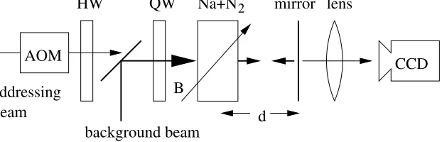
The setup of the experiment (Fig. 1) is an implementation of the single–mirror feedback scheme that has been analyzed by d’Alessandro and Firth.14 It consists of a cell containing sodium vapor in a N
2 buffer gas atmosphere
and a plane feedback mirror at a distance dbehind the medium. An enlarged and spatially filtered cw dye laser beam (background beam) is injected into the cell. The frequency of the laser beam is tuned several GHz above the sodium D1–line, the light is circularly polarized by means of the quarter–wave plate in front of the sodium cell. We
observe the transverse intensity distribution of the light field through the feedback mirror (reflectivity R = 0.915) with the help of an imaging lens and a CCD camera.
2
Na+N
QW
background beam
HW
AOM
addressing
beam
B
d
[image:2.612.154.465.25.125.2]CCD
mirror lens
Figure 1. Scheme of the experimental setup. QW: quarter–wave plate, HW: half–wave plate, AOM: acousto–optic modulator, Na+N2: sodium cell.
The idea of the experiment is that the background beam experiences a local variation of the amplitude and phase inside the sodium vapor, if there is a spatial variation of the complex susceptibility. During the propagation of the light field from the sodium vapor to the feedback mirror and back diffraction takes place and provides the spatial coupling required for the formation of structures. Since the susceptibility of the sodium vapor depends on the intensity of both the incoming and the reflected light field, certain spatial modulations of the susceptibility can stabilize themselves.
The nonlinearity of the sodium vapor originates from optical pumping between the Zeeman sublevels of the sodium ground state by the circularly polarized light. The magnetization induced by the pumping process interacts with an oblique dc magnetic field; a variation of the magnetic field allows to shape the characteristic curve, which gives the absorption and refractive indices as a function of the intensitiy for homogeneous light fields.15 This experiment is
already known to exhibit spatially extended patterns11and plane–wave optical bistability12which are both favorable
for the appearance of LS.9,16
3. EXPERIMENTAL RESULTS
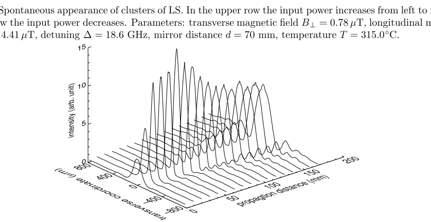
Fig. 2 shows that large-amplitude bright spots appear spontaneously on the smooth background beam when the input power is increased (top row) or decreased (bottom row). For increasing input power, the first spot appears spontaneously at P = 131 mW (c). For higher input powers in general several spots are observed which form characteristic clusters. In Fig. 2 typical examples for these clusters are shown. We observe spontaneous switching between different clusters and multistability of clusters with different orientation and different numbers of spots. Since the lifetime of a cluster is much longer than the transition time between different clusters we conclude that the clusters are stable and stationary structures and that the switching between different clusters occurs due to noise in a highly multistable system. The average number of spots that appear spontaneously increases with increasing input power.
From the facts that a single spot can appear on many different locations within the background beam, and that the spots in the clusters are neither densely packed nor display a well defined symmetry, we draw the conclusion that the spots are self-organizing localized states. The characteristic clusters of LS are formed due to the mutual interaction between LS and due to the interaction with the background beam.17
The bottom row of Fig. 2 shows the observations for decreasing input power. A comparison with the top row shows, that there is multistability between the unstructured state [(a) and (b)] and clusters containing up to three LS [(k) and (l)]. Within this range of input powers single LS can be created and erased with an addressing beam (see Fig. 1). The addressing beam has approximately the width of a LS and it can be switched on and off with an acousto–optic modulator. Due to the frequency shift of 140 MHz induced by the acousto–optic modulator, there is no need for interferometric stability between the addressing beam and the background beam. The choice between ignition or erasure of a LS is made by choosing the polarization of the addressing beam with the help of a half–wave plate. For the creation of LS, both beams have the same circular polarization, for the erasure, the polarization of the addressing beam is orthogonal to the polarization of the background.18
125 mW 127 mW 131 mW 133 mW 133 mW 135 mW
138 mW 136 mW 135 mW 132 mW 127 mW 125 mW
a)
b)
c)
d)
e)
f)
[image:3.612.87.536.22.169.2]g)
h)
i)
j)
k)
l)
Figure 2. Spontaneous appearance of clusters of LS. In the upper row the input power increases from left to right, in the lower row the input power decreases. Parameters: transverse magnetic fieldB⊥= 0.78µT, longitudinal magnetic
fieldBz= 14.41µT, detuning ∆ = 18.6 GHz, mirror distanced= 70 mm, temperatureT = 315.0◦C.
0 50
100
150 200
propagtion distance (mm) 800
400 0
−400 −800 transverse coordinate (
µ
m) 0 5 10 15
intensity (arb. unit)
Figure 3. Profiles of the intensity distribution produced by a LS during propagation from the sodium vapor to the mirror and back. Parameters: B⊥= 4.17µT,Bz= 8.23µT, ∆ = 13.5 GHz,d= 80 mm,P0= 107 mW,T = 340.0◦C.
generated by a LS as the result of such an experiment. The first profile (propagation distance z= 0 mm) shows a profile of the transmitted light field directly behind the sodium vapor. The light field experiences a higher transmission at the site of the LS and therefore there is a small maximum in the transmitted intensity distribution.
During the propagation this maximum becomes higher and smaller, the light field passes through a kind of focus. In the following section we will demonstrate that this focusing effect is due to a phase modulation of the transmitted light field, i.e. the LS acts locally as a focusing lens. The reflected light field which reenters the sodium vapor (last profile in Fig. 3,z= 2d= 160 mm) has a large intensity maximum which is surrounded by several diffraction fringes. This reinjected light field interacts again with the sodium vapor and provides the positive feedback necessary for the stabilization of the LS.
4. THEORETICAL INTERPRETATION
Under the experimental conditions described in the previous sections the sodium vapor can be modeled as aJ = 1 2 →
J0= 1
2 transition in a microscopic model of the sodium D1–line. The origin of the nonlinearity of the sodium vapor
is optical pumping, i.e. the creation of a population difference (or orientation) between the two Zeeman sublevels of the ground state. The dynamical degrees of freedom of the sodium can be reduced to a normalized Bloch vectorm which is built from components of the density matrix describing the sodium ground state11; the orientation is the
componentmz. The equation of motion form is
[image:3.612.105.524.176.392.2]Hereγis the relaxation constant,Dis the diffusion constant and ∆⊥is the Laplace–operator in the transverse plane.
The vectorΩ = (Ωx,0,Ωz−P∆) describes the precession of¯ m in an effective magnetic field. Ωx and Ωz are the corresponding Larmor frequencies of the magnetic field, the term−P∆ stems from the shift of the atomic levels by¯ the interaction with off–resonant light (’light–shift’). ¯∆ is the detuning of the laser with respect to the resonance normalized to the homogeneous linewidth. The pump rateP is proportional to the local intensity. Due to the strong diffusion, the interference of the forward and backward beam inside the medium can be neglected and the pump rate is proportional to the sum of the intensities of the forward and backward fields: P =β(|Ef|2+|Eb|2). The factorβ can be calculated from the atomic model of the D1–line (see e.g. ref.19). Note that the backward light fieldEb is a function of the magnetizationm, therefore equation (1) is nonlinear.
0.0
0.5
1.0
1.5
pump rate P
0(10
5s
−1)
0.50
0.60
0.70
0.80
0.90
1.00
[image:4.612.180.437.157.333.2]orientation
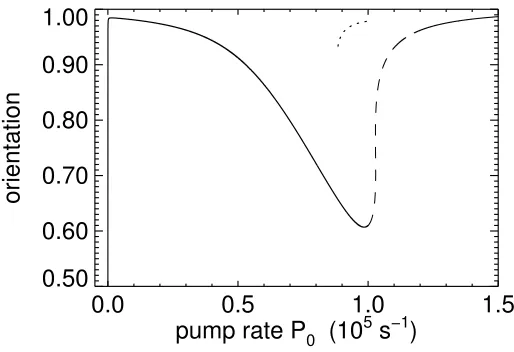
Figure 4. Characteristic curve for the plane–wave solution. The dotted branch denotes the maximum orientation of the LS. Parameters: Ωx= 1.13×10⁵ rad/s, Ωz= 9.35×10⁵rad/s, ∆ = 7.9 GHz,d= 63 mm
The effect of the sodium vapor on the light field is described by the complex susceptibility, which varies linearly with the orientation:χ=χlin(1−mz). We neglect diffraction inside the sodium vapor, since the length of the vapor
(L= 15 mm) is small compared to the propagation distance between the vapor and the feedback mirror (2d≈160 mm) and the collimation length of the laser beam (Rayleigh lengthrR≈13 m). Therefore the transmitted light field
is
Et =Efe−
1
2iχk0L. (2)
k0= 2π/λis the wavenumber of the light. Propagation over the distance 2dfrom the vapor to the mirror and back
into the vapor is described by the paraxial wave equation:
∂zE=−
i
2k0
∆⊥E . (3)
For a spatially homogeneous incoming light field Ef this system has a homogeneous solution. In Fig. 4 the orientation (component mz) of this solution is drawn as a function of the pump rateP0 of the incoming light field.
Due to the interaction of the light shift and the longitudinal magnetic field, the value of the homogeneous solution shows a pronounced minimum for Ωz−P∆¯ ≈0. The rising side of this minimum is very steep, for suitably chosen parameters the system can even show bistability of the homogeneous solution.12
yields an instability of the homogeneous solution towards a spatially extended pattern (i.e. a modulation instability). Numerical simulations show that the bifurcation towards the extended pattern is subcritical. Thus there is also a region with multistability between LS, clusters of LS and extended patterns. This finding suggests that the extended pattern can be thought of as an array of LS; however this is still a topic of ongoing investigations.
In conclusion we observe LS in a system, that has a steep gradient of the homogeneous solution (nascent optical bistability) and exhibits a subcritical modulation instability. This scenario is frequently encountered in the theoretical analysis of optical systems9,16,20,13,21 and seems to be of some generality.
0
50 100
150
distance (mm) −0.5
0.0 0.5
x (mm) 0.6 0.8 1.0 1.2 1.4 1.6
amplitude (a. u.)
0
50 100
150
distance (mm) −0.5
0.0 0.5
x (mm) 0 2 4
[image:5.612.75.541.124.265.2]phase
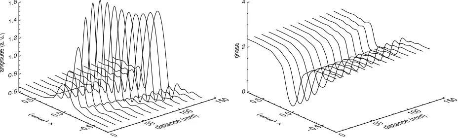
Figure 5. Numerically calculated amplitude and phase of the light field produced by a LS during the propagation between the sodium vapor and the mirror. Parameters: Ωx= 1.13×10⁵rad/s, Ωz= 9.35×10⁵rad/s, ∆ = 7.9 GHz,
d= 63 mm,P0= 0.09×10⁵s−1
In Fig. 5 the calculated variation of the amplitude and phase profiles of a LS during the propagation is shown. The variation of the amplitude shows qualitatively the same behaviour as the experimental result: the incoming light field experiences a higher transmission at the site of the LS and the light field is focused during the propagation. In the simulations as well as in the experiment, the light field reentering the sodium vapor exhibits a large peak which is surrounded by several diffraction fringes.
The phase of the transmitted light field has a pronounced minimum at the site of the LS. This phase shift is responsible for the focusing of the light field during the propagation, therefore the LS acts as a focusing lens. From this result we conclude that the LS stabilizes itself via a self–induced lensing effect.22
5. APPLICATIONS
The use of nonlinear optical systems for information processing is discussed since the discovery of optical bistability.23
Possible applications are also one of the main reasons that promoted the investigations of optical LS in the past years. In the previous sections we already mentioned the controlled switching of LS with an addressing beam. In the following we will show how these ’optical bits’ can be pinned to a fixed position in the transverse plane and we implement a simple two bit buffer register. Finally we examine the possibility of using LS to amplify modulated signals.
There are many facts which are opposed to the direct commercial usage of LS in a single–feedback mirror setup with sodium vapor. Among them is the high effort that must be made to produce the required tunable laser light and the limited number (≈10) of LS that can be created simultaneously. Therefore the intention of this section is to demonstrate these applicationsin principle and to stimulate further research on LS in systems that are more suited for commercial purposes.24–26
5.1. Optical Memory
The drift of LS in gradients of the amplitude and phase5,10,13 and the mutual interaction of LS5,27,28 has been
analyzed repeatedly in theoretical papers. In the experimental system investigated in this article, these effects lead to the appearance of characteristic clusters of LS17 (see fig. 2); similar effects have been observed for LS in a liquid
Furthermore we observe frequent changes of the position of the LS due to noise for nominally constant experimental parameters. For a practical use of LS as bits in an optical memory it is therefore inevitable to fix the positions of the LS in the transverse plane. In ref.10,13the authors make the proposal to purposely modulate the phase or amplitude
of the input light field in order to prescribe the positions of the LS. This system should also be robust with respect to small errors in the position of the addressing beam, since even LS that are created at some distance from the optimal position can drift to the final position when the addressing beam is switched off. Finally, this system can easily be reconfigured by simply changing the modulation of the input light field.
65 mW 68 mW 70 mW 70 mW 72 mW
[image:6.612.89.537.117.204.2]a)
b)
c)
d)
e)
Figure 6. Pinning of LS on positions that are prescribed by modulations in the background light field. Parameters:
B⊥ = 2.38µT,Bz= 7.55µT, ∆ = 12.0 GHz,d= 70 mm,T = 303.0◦C.
For the experiment shown in Fig. 6 this proposal has been realized in a very simple manner by introducing a quadratic aperture into the input beam and thus inducing a quadratic diffraction pattern. The small amplitude modulations appearing in the background beam can be seen in Fig. 6 (a). We are able to create a 2×2–Array of LS: When the input power is increased, the LS pop up spontaneously on the four positions prescribed by the diffraction pattern. Probably because of small misalignments in the experimental setup we did not succeed in producing bistability between the states with and without LS on all four positions simultaneously. In addition to the pinning of LS, this feature would be necessary for an optical memory.
5.2. Buffer register
Another possible application that uses LS as optical bits is demonstrated in Fig. 7. Here the feedback mirror has been slightly tilted in order to produce a shift between the LS in the sodium vapor and the reflected light field. Thus one can initiate a drift motion of stationary structures.9,30,31 In the experiment shown in Fig. 7 the direction of the
drift motion is upwards. Fort= 0µs there is one LS in the upper part of the background beam and a second LS is being created with the addressing beam in the lower part. Therefore in the following the system is in a state where two storage positions are occupied with a LS. After 64µs the upper LS has disappeared, att= 80µs a new LS has been created in the lower part. An empty storage location can be created simply by omitting the addressing beam in one cycle.
t=0
µ
s
t=16
µ
s
t=32
µ
s
t=48
µ
s
t=64
µ
s
t=80
µ
s
a)
b)
c)
d)
e)
f)
Figure 7. Optical buffer register. The LS are drifting upwards since the feedback mirror is tilted. New LS are created in the lower part of the image by the addressing beam with a frequency of 14 kHz. Parameters: B⊥= 0µT,
Bz= 14.41µT,P0= 115 mW,∆ = 11.9 GHz,d= 70 mm,T = 329.5◦C.
This all–optical buffer register could be used in optical telecommunications for the translation of serial data into parallel data, or it can serve as a buffer for the temporary storage of data.32 Since the drift velocity of the LS
[image:6.612.85.536.476.553.2]5.3. Amplification of modulated signals
In ref.7the authors propose an experiment in which the modulation of an addressing beam can be amplified when it
falls onto a LS. Here the main interest is not the amplification of the signal as a whole, but only the amplification of the modulation amplitude (i.e. thedifferential amplification) is of importance. The physical idea is to use the steep part of the LS–branch shown in Fig. 4: for these parameters, already a small modulation of the background intensity can lead to a large modulation of the orientation.
0
200
400
600
800 1000
time (
µ
s)
0.0
0.2
0.4
0.6
0.8
power (mW)
0
20
40
frequency addressing beam (kHz)
0.00
0.10
0.20
0.30
0.40
0.50
[image:7.612.84.531.112.269.2]differential gain
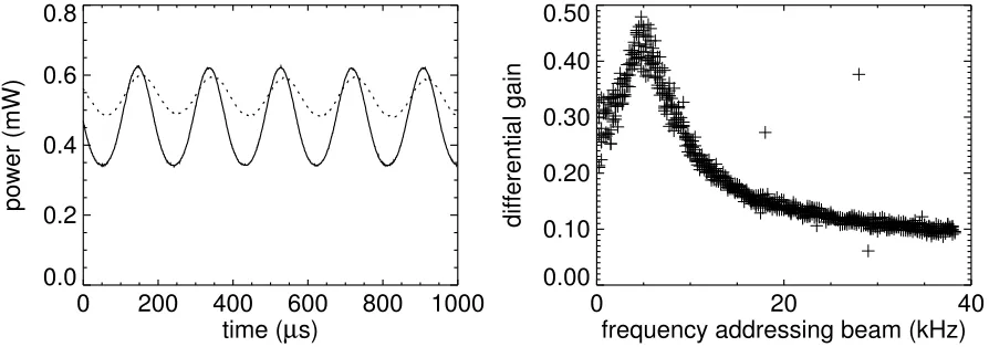
Figure 8. Differential amplification of the addressing beam by a LS. Left: power of addressing beam (straight line) and transmitted power at the site of the LS (dashed line). Right: differential gain as a function of the modulation frequency. Parameters: B⊥ = 1.79µT,Bz= 10.29µT,P0= 106 mW, ∆ = 10.29 GHz,d= 65 mm,T = 320.9◦C.
For the measurement of the differential gain the addressing beam is modulated in time and sent onto a LS. The straight curve in Fig. 8 (left) shows the power of the addressing beam; the mean power is 0.46 mW and the amplitude modulation is 0.16 mW. The dashed curve indicates the transmitted power at the site of the LS. Here, the mean power is 0.54 mW and the amplitude 0.06 mW. Therefore the ratio of the amplitudes of the transmitted signal and the input signal (i.e. the differential gain) is 0.38. In the interpretation of this result it has to be taken into account that the observation of the transmitted beam is performed through the feedback mirror whose transmission is T = 0.085. Thus it can be deduced that under the experimental conditions of Fig. 8 the modulation amplitude in front of the mirror is 0.06 mW/T ≈0.71 mW, corresponding to a differential gain of about 4.4. Therefore it can be concluded that the mechanism proposed in ref.7 works in principle. The setup used in this experiment is not
practical, however, due to the low transmission of the feedback mirror. In the case of LS in a nonlinear cavity the situation may be more favorable and high differential gains have been predicted indeed.7
According to the theoretical considerations the differential gain should vary with the modulation frequency of the addressing beam: the functional dependence is expected to follow a Lorentz curve. We observe a resonant enhancement of the gain, if the frequency of the modulation of the addressing beam is varied (see right hand side of Fig. 8) This data can be well fitted to a Lorentz curve with maximum gain at 4.8 kHz and a half width of 5.8 kHz; the resonance frequency is in the order of magnitude of the frequency of the relaxation oscillations that can be observed when the system is locally excited. This is also the order of magnitude of the Larmor oscillations which determine the fastest characteristic time scale in our system (equation (1)). In the theoretical treatment of differential gain in the nonlinear cavity, the center frequency is found to be of the order of the cavity decay rate. This is the fastest characteristic time scale of the nonlinear cavity. However, a detailed theoretical analysis of the effects determining the resonance frequency remains to be done in both systems.
ACKNOWLEDGMENTS
REFERENCES
1. A. Schreiber, B. Th¨uring, M. Kreuzer, and T. Tschudi, “Experimental investigation of solitary structures in a nonlinear optical feedback system,”Opt. Commun.136, p. 415, 1997.
2. V. B. Taranenko, K. Staliunas, and C. O. Weiss, “Spatial soliton laser: Localized structures in a laser with a saturable absorber in a self–imaging resonator,”Phys. Rev. A56, p. 1582, 1997.
3. P. L. Ramazza, S. Ducci, S. Boccaletti, and F. T. Arecchi, “Localized versus delocalized patterns in a nonlinear optical interferometer,”Quant. Semiclass. Opt. 2, p. 399, 2000.
4. G. I. Stegeman and M. Segev, “Optical spatial solitons and their interactions: universality and diversity,”Science 286, p. 1518, 1999.
5. N. N. Rosanov and G. V. Khodova, “Diffractive autosolitons in nonlinear interferometers,”J. Opt. Soc. Am. B 7, p. 1057, 1990.
6. W. J. Firth and G. K. Harkness, “Cavity solitons,”Asian J. of Phys.7, p. 665, 1998.
7. L. Spinelli and M. Brambilla, “Signal amplification by means of cavity solitons in semiconductor microcavities,” Europ. Phys. J. D6, p. 523, 1999.
8. G. S. McDonald and W. J. Firth, “Spatial solitary-wave optical memory,”J. Opt. Soc. Am. B7, p. 1328, 1990. 9. N. N. Rosanov, “Switching waves, autosolitons, and parallel digital-analogous optical computing,”Proc. SPIE
1840, p. 130, 1991.
10. W. J. Firth and A. J. Scroggie, “Optical bullet holes: Robust controllable localized states of nonlinear cavity,” Phys. Rev. Lett.76, p. 1623, 1996.
11. T. Ackemann, Y. A. Logvin, A. Heuer, and W. Lange, “Transition between positive and negative hexagons in optical pattern formation,”Phys. Rev. Lett.75, p. 3450, 1995.
12. T. Ackemann, A. Heuer, Y. A. Logvin, and W. Lange, “Light–shift induced level crossing and resonatorless optical bistability in sodium vapor,”Phys. Rev. A56, p. 2321, 1997.
13. L. Spinelli, G. Tissoni, M. Brambilla, F. Prati, and L. A. Lugiato, “Spatial solitons in semiconductor microcav-ities,”Phys. Rev. A58, p. 2542, 1998.
14. G. d’Alessandro and W. J. Firth, “Spontaneous hexagon formation in a nonlinear optical medium with feedback mirror,”Phys. Rev. Lett.66, p. 2597, 1991.
15. W. Lange and T. Ackemann, “Alkaline vapors with single-mirror feedback – a model system for pattern forma-tion,”Asian J. Phys. 3, p. 439, 1998.
16. M. Tlidi, P. Mandel, and R. Lefever, “Localized structures and localized patterns in optical bistability,” Phys. Rev. Lett.73, p. 640, 1994.
17. B. Sch¨apers, M. Feldmann, T. Ackemann, and W. Lange, “Interaction of localized strucutures in an optical pattern-forming system,”Phys. Rev. Lett.85, p. 748, 2000.
18. B. Sch¨apers, T. Ackemann, and W. Lange , unpublished.
19. W. Lange, Y. A. Logvin, and T. Ackemann, “Spontaneous optical patterns in an atomic vapor: Observation and simulation,”Physica D96, p. 230, 1996.
20. D. Michaelis, U. Peschel, and F. Lederer, “Multistable localized structures and superlattices in semiconductor optical resonators,”Phys. Rev. A56, p. 3366, 1997.
21. K. Staliunas, “Stabilization of spatial solitons by gain diffusion,”Phys. Rev. A61, p. 053813, 2000.
22. R. Neubecker and T. Tschudi, “Self–induced mode as a building element of transversal pattern formation,”J. Mod. Opt.41, p. 885, 1994.
23. H. M. Gibbs,Optical Bistability: Controlling Light with Light, Academic Press, Orlando, 1985.
24. V. B. Taranenko, I. Ganne, R. J. Kuszelewicz, and C. O. Weiss, “Patterns and localized structures in bistable semiconductor resonators,”Phys. Rev. A61, p. 063818/1, 2000.
25. R. Kuszelewicz, I. Ganne, I. Sagnes, G. Slekys, and M. Brambilla, “Optical self–organization in bulk and multiquantum well GaAlAs microresonators,”Phys. Rev. Lett.84, p. 6006, 2000.
26. T. Ackemann, S. Barland, J. R. Tredicce, M. Cara, S. Balle, R. J¨ager, P. M. Grabherr, M. Miller, and K. J. Ebeling, “Spatial structure of broad-area vertical-cavity regenerative amplifiers,”Opt. Lett.25, p. 814, 2000. 27. C. P. Schenk, P. Sch¨utz, M. Bode, and H.-G. Purwins, “Interaction of self–organized quasiparticles in a two–
dimensional reaction–diffusion system: The formation of molecules,”Phys. Rev. E57, p. 6480, 1998.
29. M. Kreuzer, B. Th¨uring, and T. Tschudi, “Creation, dynamics and stability of localized states in a nonlinear optical single feedback system,”Asian J. Phys. 3, p. 678, 1998.
30. G. Grynberg, “Drift instability and light–induced spin waves in an alkali vapor with feedback mirror,” Opt. Commun.109, p. 483, 1994.
31. J. P. Seipenbusch, T. Ackemann, B. Sch¨apers, B. Berge, and W. Lange, “Drift instability and locking behavior of optical patterns,”Phys. Rev. A56, p. 4401, 1997.