Tunable Electron Multibunch Production in Plasma Wakefield
Accelerators
B. Hidding1,2,3, O. Karger2, G. Wittig2, C. Aniculaesei2, D. Jaroszynski1, B.W.J. McNeil1, L.T. Campbell2, M.R. Islam1, B. Ersfeld1, Z.-M. Sheng1, Y. Xi,3, A. Deng3, J.B. Rosenzweig3, G. Andonian3,4, A. Murokh4, M.J. Hogan5, D.L. Bruhwiler6,7, E. Cormier8
1Department of Physics, SUPA, Strathclyde University,
Glasgow, UK, G4 0NG, 2Department of Experimental Physics, University of Hamburg & CFEL, 3 Department of Physics and Astronomy,
University of California, Los Angeles, USA,
4 RadiaBeam Technologies, Santa Monica, USA, 5 SLAC,
Stanford, USA, 6 University of Colorado at Boulder, Center for Integrated Plasma Studies, Boulder,
Colorado 80309, USA, 7 RadiaSoft LLC, Boulder, Colorado 80304, USA, 8 Tech-X Corp.,
5621 Arapahoe Ave., Boulder 80303, USA
(Dated: March 6, 2014)
Abstract
Synchronized, independently tunable and focused µJ-class laser pulses are used to release mul-tiple electron populations via photo-ionization inside an electron-beam driven plasma wave. By
varying the laser foci in the laboratory frame and the position of the underdense photocathodes
in the co-moving frame, the delays between the produced bunches and their energies are adjusted.
The resulting multibunches have ultra-high quality and brightness, allowing for hitherto
impossi-ble bunch configurations such as spatially overlapping bunch populations with strictly separated
energies, which opens up a new regime for light sources such as free-electron-lasers.
Plasma wakefield acceleration [1, 2] offers the advantage of ultrahigh accelerating gra-dients of the order of tens of GV/m or more, which allows for acceleration of particles to ultrarelativistic energies within few cm – in contrast with conventional accelerators based on metallic cavities, where breakdown limits the accelerating fields to tens of MV/m. An-other fundamental difference is that in conventional accelerators a large number of cavities are needed, in contrast to plasma accelerators where one transient plasma-cavity in the co-moving frame is sufficient. This plasma cavity is generated on the fly, either by an in-tense electron beam or a laser pulse with a duration τ < λp/2, where λp is the relativistic plasma wavelength, which is equal to the plasma cavity length. GeV-scale energies have been demonstrated both in laser wakefield accelerators (LWFAs) [3–5] and in beam-driven plasma wakefield accelerators (PWFAs) in cm to meter-scale [6] plasma sections. Witness bunch(es) to be accelerated in these systems can be injected from an external source or generated directly within the plasma itself. In this Letter, we show how ultra-high quality electron bunch trains can be simultaneously generated in one and the same plasma cavity and tuned independently over a large parameter range. Such highly tunable multibunches have been hitherto inaccessible but are highly important for various fields, such as driver-witness plasma wakefield acceleration, and light sources based on Compton scattering or (multi-color [7]) free-electron lasers (FELs).
within the first wave bucket in order to produce distinct accelerated electron populations that may differ in energy and/or space. To this end, we use an envelope approximation to describe the release laser pulse(s), avoiding computationally expensive resolution of the laser pulse oscillations, and a static current to model the drive beamId. This approach does not capture the full physics of transverse oscillations imparted by the laser pulse, but is ideally suited to explore the bunch generation and acceleration over multi-cm scale distances to
e- energy / GeV e- energy / MeV
driver bunch E / GV/m
E / GV/m
ξrls
e- energy / MeV E / GV/m
10.9 cm
11.9 4.21
-117 e- energy / MeV
E / GV/m
44
1 mm 1.1 mm
0
L1 L2 L3
ξtrap ξtrap ξrls ξrls ξtrap driver bunch a) f)
c) d)
520 0 3.50 mm 3.35 mm 138 0 81 305
2.28 mm 2.45 mm
-50 µm 50 µm 50 µm -50 µm 38 187 0 109 109 0 µm e) b)
distance ξ / µm
ene rgy / G eV 5 10 9 8 7 6 10.9 cm 10 20
L1 L2 L3
B1B2 B3 B1 B2 B3
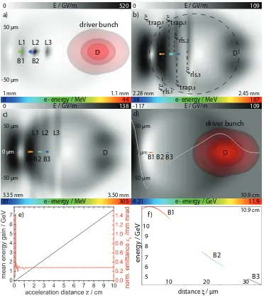
[image:3.612.120.492.211.630.2]B1 B2 B3 30 B1 B2 -50 µm 0 µm 50 µm D D D D
FIG. 1: 3D-PIC simulations of triple-bunch B1–B3 generation with three laser pulses L1–L3. In a)-c) the sum of the electric field shows the y-polarized L1–L3 whereas in d) the
10+ GeV energies. Furthermore, it offers additional insights into betatron phase mixing effects [10, 14] independent of the residual momentum of the laser oscillation kick. For further simulation speed-up, we use Li as the LIT species and Li+ as the HIT component to examine the underlying scheme. Using different LIT/HIT media such as H and He [9] is possible without loss of generality [8]. The requirements of the laser pulses for releasing electrons locally confined within the blowout region are straightforward: a) they should be strongly focused and have a Rayleigh range ZR =πw20/λ < λp, where w0 is the beam waist and λ the laser wavelength, and b) the focused laser intensities must be sufficient to ionize the HIT component. An upper limit is given by the barrier suppression ionization (BSI) threshold [15], which in case of Li+ with an ionization energy ofW
ion ≈75.6 eV corresponds to IBSI ≈ 4×10⁹ ×Wion4 /(Z2) ≈ 3.2×10¹⁶W/cm
−2 and an a 0 ≈
q
Iλ2[µm2]
1.37×10¹⁸V/m ≈ 0.12,
where Z is the ionic charge and λ = 0.8µm. As a basic principle, low Wion and short λ are desirable [11] to reduce the peak electric fields required for ionization. This is important because the electric field of the HIT ionizing laser pulse determines the residual momentum of the newly born electrons, because pre-ionization or self-ionization of the LIT medium is easier, and because the gap to the HIT level may be larger.
Figure 1 shows the release, trapping and acceleration of three electron bunches (B1-B3) generated by three consecutive laser pulses (L1-L3) in a strong blowout region set up by a FACET-class drive beam D with a size σz = σr = 20µm and charge of Q ≈ 3 nC in a Li plasma. The LIT plasma densityne≈1.5×1017cm−3 corresponds to a plasma wavelength
λp ≈ 75µm. Each laser pulse has a duration of τ = 25 fs (FWHM), and they follow D with intervals of ∆ξ = 20µm. In the lab frame, the spots with w0 = 5µm FWHM at an intensity of a0 = 0.14 are separated by ∆z = 20µm; these are the release positions of the HIT electron populations.
In figure 1 a), the peak electric field of Esum≈ 520 GV/m is produced by the focused L2, which is in the process of liberating HIT electrons which form bunch B2, while L3 has not yet reached its focus. The trapping positions can be predicted from the potential differences
ψtrap −ψrls = −1 + p
1 +P2
be modelled asψ = (r2−R2)/4 wherer =pξ2+y2+x2 [18]. For electrons born on axis at
ξrls, forP⊥ ≤mc2 andγd1 the trapping position is ξtrap ≈ − p
4 +ξ2
rls, whereξ = 0 is the blowout region center. This is reflected in figure 1 b), where the underdense photocathode action is complete and bunches B1–B3 are formed and trapped. While the laser pulses continue to diffract, the accelerating system is quasistatic and electrons are accelerated (fig. 1 b-d) with linear energy gain. The evolution of the energy gain ∆E and the normalized emittance n, averaged over all three bunches, is shown in fig. 1 e). Although L1–L3 are approximated by envelopes, the saturated emittance ofn ≈0.3π mm mrad observed in the simulations is in good agreement with the crude scaling for the laser pulse contribution to the emittance in [9], which would predict n≈w0a0/23/2 ≈0.2π mm mrad. The emittance would be further decreased using HIT media with lower ionization thresholds, such as He. In fig. 1 f) we show the corresponding longitudinal phase space distribution of the triple bunch afterz = 10.9 cm in this quasistatic system (see supplemental material movie), where B2 and B3 have a correlated energy chirp ∂W/∂ξ < 0, but for B1, located at the end of the blowout region, in the first part ∂W/∂ξ >0, while in the second part ∂W/∂ξ <0. The peaked energy structure of B1 reflects the fact that this bunch resides in the accelerating electric field mimimum E, which opens up strategies for energy spread minimization.
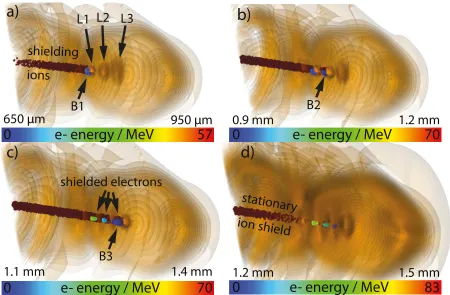
for the forming B2 and then also for the already formed B1, which still has a low energy. In figure 2 c), the same happens with L3 and B3, and in figure 2 d) the complete ionization and shielding process is complete. Each ion shield has a longitudinal shape with a volume of approximately Vshield≈ZRπ(w0/2)2.
e- energy / MeV
57
shielding
ions
L1
a)
b)
1.2 mm
950 µm
e- energy / MeV
0
0
70
650 µm
L2 L3
B1
B2
0.9 mm
c)
d)
shielded electrons
e- energy / MeV
0
B3
1.4 mm
1.1 mm
stationary
ion shield
1.5 mm
1.2 mm
e- energy / MeV
[image:6.612.81.531.186.481.2]0
70
83
FIG. 2: Transient ion shielding. HIT ions (brown spheres) shield the forming electron bunches B1–B3 produced consecutively by laser pulses L1–L3 with zrls,1 < zrls,2 < zrls,3 to
increase the shielding effect.
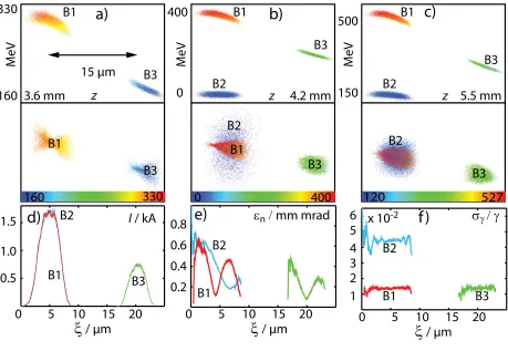
yet have substantially different energies due to the different acceleration times (see figure 3 c) and supplemental material). Such bunch configurations are impossible with conventional accelerators. Slice properties of the three bunch populations of figure 3 c) are plotted for the current I (d), normalized emittance n (e) and relative energy spread σγ/γ (f). It is notable that whileIB1 ≈IB2,IB3 < IB1,B2 although the three laser pulses are identical. This is attributed to the fact thatξrls,2 is located much closer to the center of the blowout region, where the plasma wakefields are significantly lower than at ξrls,1,2. Superposition of laser and plasma fields results in reduced ionization yields and has to be taken into account when targetting a desired bunch charge.
a)
400b)
M eV
c)
500 150 M eV 5.5 mm0 4.2 mm
M
eV
160 330
3.6 mm z
120 527
0 400
160 330
15 µm
z z
d)
e)
f)
B1 B3 B3 B1 B2 B2 B1 B3 B1 B3 B2 B1 B3 B3 B3 B2 B2 B2 B1 B1 B1 B2 B3 1.5 1.0 0.5
0 5 10 15 20
ξ
/ µmξ
/ µmξ
/ µmI / kA
0 5 10 15 20 0 5 10 15 20
[image:7.612.76.535.285.602.2]εn / mm mrad 6 x 10⁻² σγ / γ 5 4 3 2 1 0.8 0.6 0.4 0.2
FIG. 3: Longitudinal phase space of three electron populations B1–B3 where B1 and B2 overlap in space but have distinct energies (a-c). For each population, the sliceI (d), n (e)
and σγ/γ (f) after 5.5 mm acceleration are given.
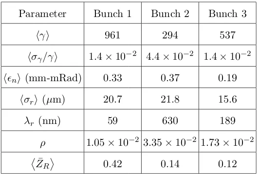
TABLE I: FEL parameters
Parameter Bunch 1 Bunch 2 Bunch 3
hγi 961 294 537
hσγ/γi 1.4×10⁻² 4.4×10⁻² 1.4×10⁻²
hni (mm-mRad) 0.33 0.37 0.19
hσri (µm) 20.7 21.8 15.6
λr (nm) 59 630 189
ρ 1.05×10⁻² 3.35×10⁻² 1.73×10⁻² ¯
ZR
0.42 0.14 0.12
potential of the bunches to drive FEL interaction in 1-D using the Puffin FEL simulation code [19], from which the notation used below is taken. Puffin models the FEL interactions of the multibunches self-consistently within the broad bandwidth radiation fields emitted. The electron distribution evolution of the multibunches, e.g. due to energy chirps and the relative motion of the electron bunches throughout the FEL interaction, are also effectively modelled. An helical undulator of period λu = 1.5 cm and r.m.s. undulator parameter ¯
au = 2.5 is used, with focusing of the multibunches provided by the ‘natural focusing’ of the undulator. Relevant parameters that determine the FEL interaction for each of the three electron bunches are given in Table I where hγi is the mean Lorentz factor, hσγ/γi is the mean relative r.m.s. slice energy spread, n is the r.m.s. normalised emittance, hσri is the mean matched bunch radius, λr is the resonant FEL wavelength, ρ is the FEL parameter and Z¯R
= πF is the mean Rayleigh range scaled with respect to the FEL gain length
lg =λu/4πρ, so that F is the Fresnel number for a gain length [20].
For each of the individual bunches the normalized emittance criterion for FEL lasing of
n < λrhγi/4π is seen to be well satisfied. When matched to the undulator focusing, these small emittances imply the matched bunch radii are relatively small. Due to these relatively dense and fine bunches the FEL coupling parameter ρ, at least for the lower energy bunch, approaches the limit where space-charge effects may need to be considered for more detailed modelling [21]. The small matched bunch radii also imply that Z¯R
diffraction from the bunches will reduce the effective FEL gain length.
An important criterion to allow efficient FEL lasing, irrespective of higher dimensional effects, is that the slice energy spread hσγ/γi ρ, which is not satisfied here for any of the bunches at the start of the FEL interaction. Nevertheless, as the bunches propagate through the undulator, the lowest energy bunch B2 quickly rotates and stretches in longitudinal phase space. As the bunch stretches, the slice energy spread reduces [22] until the slice energy spread criterion becomes satisfied and FEL lasing may commence.
Figure 4 plots the radiation output and electron phase-space distribution of the multi-bunches following propagation through a 3 meter undulator to investigate small signal be-haviour. Comparison with the electron distributions of figure 3 shows that the lengths of the two higher energy bunches B1 and B3, have not changed significantly from∼10µm. In contrast, the low-energy B2 has been stretched to ∼10 times its initial length, so reducing its slice energy spread by approximately the same factor. The energy spread criterion then becomes satisfied and FEL lasing can commence. Lasing around the maximum current of B2 is seen at ct−z ∼140µm and about ω/ω2 ∼1 in the spectral power. Smaller spectral powers are seen due to spontaneous emission from B3 and B1 about ω/ω2 ∼ 4 and ∼ 13 respectively. Lower frequency emission ω/ω2 <0.5 is due to coherent spontaneous emission from the multibunches. An animation of the interaction from the start of the undulator is available in the supplemental material.
The analyzed, flexible scheme shows that highly tunable electron bunches can be gener-ated, allowing for multi-bunch trains and hitherto impossible exotic configurations such as spatially overlapping electron populations with different energies. Thanks to the strictly cor-related energy chirps and high brightness of these bunches FEL-class quality can be reached in the 1D case. Further optimization of energy spread, emittance and brightness is possible and may be a unique route to achieve saturation with plasma-accelerated electron bunches. For example, the emittance can be reduced by at least an order of magnitude simply by using lower ionization threshold media such as helium. This may pave the way towards highly tunable plasma-based multi-bunch, multi-color FEL systems.
B2
B3
B1
B1
B2
B3
FIG. 4: Puffin 1-D simulation FEL output after 3 m undulator. Top: radiation power, middle: electron energies scaled tohγ2i, bottom: Spectral radiation power, with respect to
the peak value,Pn=P/Ppk, as a function of the frequency scaled to the mean resonant frequencyω2 of B2.
Research Scientific Computing Center, which is supported by DOE DE-AC02- 05CH11231, and of JUROPA, and of HLRN.
[1] P. Chen, J. M. Dawson, R. W. Huff, and T. Katsouleas, Phys. Rev. Lett.54, 693 (1985), URL
http://link.aps.org/doi/10.1103/PhysRevLett.54.693.
[2] J. B. Rosenzweig, D. B. Cline, B. Cole, H. Figueroa, W. Gai, R. Konecny, J. Norem, P.
Schoes-sow, and J. Simpson, Phys. Rev. Lett. 61, 98 (1988), URL http://link.aps.org/doi/10.
[image:10.612.82.535.71.421.2][3] W. P. Leemans et al., Nature Physics 2, 696 (2006).
[4] S. Karsch, J. Osterhoff, A. Popp, T. P. Rowlands-Rees, Z. Major, M. Fuchs, B. Marx, R.
Hor-lein, K. Schmid, L. Veisz, et al., New Journal Of Physics 9, 415 (2007).
[5] X. Wang, R. Zgadzaj, N. Fazel, Z. Li, S. A. Yi, X. Zhang, W. Henderson, Y.-Y. Chang,
R. Korzekwa, H.-E. Tsai, et al., Nat Commun 4, (2013).
[6] I. Blumenfeld et al., Nature445, 741 (2007).
[7] D. A. Jaroszynski, R. Prazeres, F. Glotin, and J. M. Ortega, Phys. Rev. Lett.72, 2387 (1994).
[8] B. Hidding et al., german Patent DE 10 2011 104 858.1, US/PCT patent Ser. No.
PCT/US12/043002.
[9] B. Hidding, G. Pretzler, J. B. Rosenzweig, T. K¨onigstein, D. Schiller, and D. L.
Bruh-wiler, Phys. Rev. Lett. 108, 035001 (2012), URL http://link.aps.org/doi/10.1103/
PhysRevLett.108.035001.
[10] Y. Xi, B. Hidding, D. Bruhwiler, G. Pretzler, and J. B. Rosenzweig, Phys. Rev. ST
Ac-cel. Beams 16, 031303 (2013), URL http://link.aps.org/doi/10.1103/PhysRevSTAB.16.
031303.
[11] B. Hidding, J. B. Rosenzweig, Y. Xi, B. O’Shea, G. Andonian, D. Schiller, S. Barber,
O. Williams, G. Pretzler, T. K¨onigstein, et al., AIP Conference Proceedings1507, 570 (2012),
URLhttp://link.aip.org/link/?APC/1507/570/1.
[12] F. Li, J. F. Hua, X. L. Xu, C. J. Zhang, L. X. Yan, Y. C. Du, W. H. Huang, H. B. Chen, C. X.
Tang, W. Lu, et al., Phys. Rev. Lett. 111, 015003 (2013), URL http://link.aps.org/doi/
10.1103/PhysRevLett.111.015003.
[13] C. Nieter and J. R. Cary, Journal of Computational Physics 196, 448 (2004), ISSN
0021-9991, URL http://www.sciencedirect.com/science/article/B6WHY-4B954G3-1/2/
675d7d4de2f99f1448034cb90ce46f8e.
[14] X. L. Xu et al., Phys. Rev. Lett. 112, 035003 (2014), URL http://link.aps.org/doi/10.
1103/PhysRevLett.112.035003.
[15] S. Augst, D. D. Meyerhofer, D. Strickland, and S. L. Chin, J. Opt. Soc. Am. B8, 858 (1991).
[16] A. Pak, K. A. Marsh, S. F. Martins, W. Lu, W. B. Mori, and C. Joshi, Phys. Rev. Lett. 104,
025003 (2010), URLhttp://link.aps.org/doi/10.1103/PhysRevLett.104.025003.
[17] M. Chen, E. Esarey, C. B. Schroeder, C. G. R. Geddes, and W. P. Leemans, Physics of Plasmas
[18] I. Kostyukov, E. Nerush, A. Pukhov, and V. Seredov, Phys. Rev. Lett. 103, 175003 (2009),
URLhttp://link.aps.org/doi/10.1103/PhysRevLett.103.175003.
[19] L. T. Campbell and B. W. J. McNeil, Physics of Plasmas19, 093119 (pages 13) (2012), URL
http://link.aip.org/link/?PHP/19/093119/1.
[20] B. McNeil and N. Thompson, Nature Photonics 4, 814 (2010).
[21] J. Murphy, C. Pellegrini, and R. Bonifacio, Optics Communications 53, 197
(1985), ISSN 0030-4018, URL http://www.sciencedirect.com/science/article/pii/
0030401885903311.
[22] A. R. Maier, A. Meseck, S. Reiche, C. B. Schroeder, T. Seggebrock, and F. Gr¨uner, Phys.