IAC-12-C1.9.7
ATTITUDE MOTION PLANNING FOR A SPIN STABILISED DISK SAIL
Craig Maclean
Advanced Space Concepts Laboratory, Glasgow, UK [email protected]
James Biggs
Advanced Space Concepts Laboratory, Glasgow, UK [email protected]
While solar sails are capable of providing continuous low thrust propulsion the size and flexibility of the sail structure poses difficulties to their attitude control. Rapid slewing of the sail can cause excitation of structural modes, resulting in flexing and oscillation of the sail film and a subsequent loss of performance and decrease in controllability. Disk shaped solar sails are particularly flexible as they have no supporting structure and so these spacecraft must be spun around their major axis to stiffen the sail membrane via the centrifugal force. In addition to stiffening the structure this spin stabilisation also provides gyroscopic stiffness to disturbances, aiding the spacecraft in maintaining its desired attitude. A method is applied which generates smooth reference motions between arbitrary orientations for a spin-stabilised disk sail. The method minimises the sum square of the body rates of the spacecraft, therefore ensuring that the generated attitude slews are slow and smooth, while the spin stabilisation provides gyroscopic stiffness to disturbances. An application of Pontryagin’s maximum principle yields an optimal Hamiltonian which is completely solvable in closed form. The resulting analytical expressions are a function of several free parameters enabling parametric optimisation to be used to provide reference motions which match prescribed boundary conditions on the initial and final configurations. The generated reference motions are utilised in the repointing of a70mradius spin-stabilised disk solar sail in a heliocentric orbit, with the aim of assessing the feasibility of the motion planning method in terms of the control torques required to track the motions.
Key words:solar sail, motion planning, geometric control·
I. NOMENCLATURE
ac Characteristic acceleration of solar sail(m/s2)
¯
aSRP Acceleration due to solar radiation pressure(m/s2)
A1, A2, A3 Basis of the Lie algebra onsu(2)
Ar Reflective area(m)
¯
FSRP Solar radiation pressure force(N)
ˆi,ˆj,kˆ Basis of the body reference frame ˆ
I,J ,ˆ Kˆ Basis of the heliocentric ecliptic reference frame
J1, J2, J3 Principal moments of inertia of
spacecraft(kgm2)
ma Attached mass (excluding sail)(kg)
ms Sail mass(kg)
ˆ
n Sail normal unit vector
¯
N Control torques(N)
P Mean solar radiation pressure at 1AU(N/m2)
¯
q Quaternions of body frame with re-spect to RTN frame
¯
qe Quaternion error
¯
r Radial vector from Sun to space-craft(m)
¯
rmp Centre of mass to centre of pressure vector(m)
ry, rz Position of sliding masses along y and z body axes(m)
ˆ
R,T ,ˆ Nˆ Basis of the RTN reference frame
¯
R(t) Kinematics on SU(2)
Rob Rotation matrix from RTN to body frame
v Spin rate of spacecraft(rad/s) α Cone angle(degrees)
δ Clock angle(degrees)
σa Attached mass assembly loading
(kg/m2)
σs Sail assembly loading(kg/m2)
¯
ωbi Inertially referenced body rates
(rad/s) ¯
ωbo RTN referenced body rates(rad/s)
¯
ωoi(b) Orbital rate with respect to inertial
frame, expressed on body reference frame components(rad/s) ¯
ωe Angular velocity error(rad/s)
II. INTRODUCTION
sails to be designed and built. Solar sailing has gath-ered considerable interest as it has the ability to provide continuous, low thrust propulsion without the need for propellant, enabling mission lifetimes to be extended and the creation of previously unattainable orbits. Ex-amples of missions enabled by solar sailing include the GeoSail mission [1, 2], the Solar-Polar Orbiter [3] and the Interstellar Heliopause Mission [4]. Yet while a large body of work has been carried out into the orbital dynamics of solar sails, the practical attitude control required to achieve these missions has been somewhat neglected with most papers simply deriving the instan-taneous changes in sail attitude necessary to achieve a certain trajectory. However solar sails are flexible structures with large moments of inertia which poses significant problems to their attitude control.
The flexible nature of solar sails means that manoeuvre times are necessarily large to avoid excessive excitation of the sail structure due to large or impulsive control torques. Moreover conventional actuators such as reac-tion wheels are often impractical for solar sail attitude control. Solar sails can be subjected to large gravity gradient torques meaning that reaction wheels quickly saturate in planet centred orbits [5], unless the orbit is carefully chosen [6]. Furthermore reaction wheel size increases with sail size and may become undesirably high for large solar sails, with the added mass an im-pediment to their launch and operation. In addition for missions far from Earth magnetorquers cannot be used for desaturation, meaning cold gas or electric thrusters for example would have to be used. However thrusters are undesirable for solar sail attitude control as fast im-pulsive torques will excite the sail structure and the pro-pellant ejected may contaminate the sail. Thrusters also have a finite supply of propellant which may reduce the operational mission lifetime.
As a result of the difficulties with conventional ac-tuators, several new methods of actuating solar sails have been proposed. Wie, who carried out the first large body of work on the attitude control of solar sails in Earth centred orbits [5, 7], examined the use of controllable booms to change the offset between the centre of pressure and centre of mass of the space-craft and so produce the control torques. The torques produced are continuous, lessening the impact on the sail membrane, and no propellant is expended. How-ever this method posed considerable engineering chal-lenges related to the structure of the control booms, with boom size increasing with solar sail size. Con-trollable sliding masses along sail struts have also been studied as a means of producing control torques via a changing centre of mass centre of pressure offset [8]. In these cases the dynamics of the system were lin-earised and solved to give the required euler angles, which were then tracked using a proportional-integral-derivative (PID) controller. The sliding ballast method was used to produce the attitude control necessary to implement a transfer to Mercury in [9], with inverse control used to derive the position of the masses neces-sary to produce the required torques. The sliding
bal-last method was extended by [10, 11] who used both a feedforward controller based on the eigenaxis theorem to compute the attitude manoeuvre and a feedback con-troller to account for the position and angular velocity errors. The authors in [12] utilised the sliding ballast method for quaternion feedback repointing in addition to BDOT control for detumbling of a small sail in Earth orbit. Wie combined the sliding ballast method with tip mounted pulsed plasma thrusters (PPTs), with the PPTs employed to control the spin rate [8]. In this paper the desired euler angles were again found and tracked us-ing PID control.
Control vanes and electrochromic surfaces have also been proposed as actuation methods for solar sails. The use of control vanes, small reflective surfaces located at the sail extremities, was described in [8, 13] and tested in simulation. However control vanes require mechan-ical actuation to control their articulation, adding extra complexity. Funase [14] detailed a system, included on the spinning IKAROS sail, to provide two-axis stabil-isation by switching the reflectivity of electrochromic sections. Switching the reflectivity between two dif-ferent states changes the torque due to solar radiation pressure (SRP) acting on the sail, and can be regulated to produce the required control torques.
While challenges to their implementation remain, slid-ing ballast masses and electrochromic control seem to be the most feasible methods for solar sail actuation at present as neither utilise propellant mass and both pro-vide continuous control torques which should lessen the impact on the sail structure. Therefore, in this pa-per we look to assess the feasibility of using actuators that can apply a continuous torque and see if the torque requirement is within the range of current solar sail technologies such as sliding ballast masses and elec-trochromic control.
This paper tackles the attitude control of a spin sta-bilised solar sail using a motion planning method, de-rived through the framework of geometric control the-ory, which minimises the body rates of the space-craft. With spin stabilisation the entire spacecraft ro-tates around its own pointing axis using the gyroscopic effect [15]. Spin stabilisation is vital for disk type so-lar sails as they generally do not have any supporting structure and so are very susceptible to flexing. These sails rely on the stiffening effect of the centrifugal force brought about by the spin [13]. Therefore in order to re-duce the effect on the structure of the sail during slew-ing, it may be beneficial to limit the body rates around the non-spinning axes.
op-timal Euler Lagrange approach of calculus of varia-tions were used to solve problems such as time-optimal attitude control [19] and the minimum fuel problem for a fixed time horizon [20]. These local methods have the added complexity of numerically solving two point boundary value problems onboard the spacecraft. The Hamilton-Jacobi-Bellman (HJB) approach from dynamic programming is globally stabilising, but is merically intractable. Solving it off-line is possible nu-merically, [21] but the global optimal solution is only approximated up to a certain order, which cannot be too high for practical implementation.
In this paper an application of the method outlined in [22] is applied to the motion planning in order to try to improve the control of a spinning disk solar sail. Using the mechanisms of geometric control theory, the kine-matics of the spacecraft are written in terms of the Lie algebra on SU(2) and an optimal Hamiltonian derived via an application of Pontryagin’s maximum principle. This leads to the derivation of analytical expressions for the optimal angular velocities and the time evolu-tion of the quaternions. These analytical expressions can then be parametrically optimised to meet boundary conditions imposed on the final pointing direction. The motion planning method is illustrated in simulation for a 70m radius spinning disk sail in a heliocentric orbit. References are tracked using a conventional quaternion feedback controller and assuming ideal actuators which are capable of providing a continuous torque. This will provide an initial analysis of the required torques to perform certain motions which will give an indication of the type of actuators which could feasibly be used. It is shown that the method can be used to perform slews typical of an inclination change manoeuvre for a solar sail in a heliocentric orbit.
This paper serves as a first step in designing attitude manoeuvres for solar sails which initially concentrates on minimising body rates to avoid excitation. The ex-tension to a multi-objective function including torque will be considered elsewhere.
III. MODELS
While the solar sail is in reality a flexible structure, in this paper the simplifying assumption is made that the spacecraft can be treated as a rigid disk. This assumption is feasible as the attitude of the sail disk will be moving at such a slow rate that the flexible structure will not be excited. The general equations describing the attitude control problem are then that of a rigid body with external forces describing the effect of the actuators and perturbations.
Reference Frame Definitions
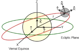
The spacecraft under consideration is in orbit around the Sun. The centre of the Sun is chosen as the origin of a heliocentric ecliptic reference system with basis vectorsI,ˆJ ,ˆKˆ. As in [23], the X and Y axes lie in the ecliptic plane towards the vernal equinox and winter solstice positions of the Earth respectively, with the
[image:3.595.331.489.96.198.2]Z-axis completing the orthonormal reference frame. The co-ordinate system is shown in Figure 1.
Figure 1: Heliocentric ecliptic and RTN co-ordinate systems.
Also shown in Figure 1 is the Radial-Transverse-Normal (RTN) reference frame used to describe the orbit of the spacecraft. In this reference frame Rˆ is parallel with the radial vector, Nˆ is parallel with the orbit normal andTˆcompletes the orthonormal frame. A body fixed reference frame (BRF) with basisˆi,ˆj,kˆis rigidly attached to the centre of mass of the spacecraft. The body and RTN frames are coincident when the sail attitude angles (cone angle αand clock angle δ) are zero. The body ratesω¯bo = [ω1bo ω2bo ω3bo]T describe the rotation of the body frame with respect to the orbit frame.
Finally, a non-spinning frame (NSF) which is fixed to the x-axis of the body frame but does not spin is employed. Since the spacecraft is symmetric, only the direction of the spin axis is of importance (for pointing of the thrust vector.) Therefore the non-spinning frame is employed to show that the spin-axis of the sail has achieved a certain orientation with respect to the orbit frame when the angular velocities around the non-spinning axes are brought to zero.
Kinematic Model
The attitude kinematics of the spacecraft in the body frame with respect to the RTN orbit frame can be pa-rameterised using quaternions:
d¯q dt =
1
2Ω¯q (1)
Where q¯ = [q0 q1 q2 q3]T denotes the
quater-nions which represent the attitude of the spacecraft in the body frame with respect to an RTN orbit frame, and
dq¯
dttheir rate of change. Note that the subscriptbo(body with respect to orbit) is omitted in the description of the quaternions and unless otherwise stated the quaternions represent the attitude of the body frame with respect to the orbit frame. The skew symmetric matrixΩis given by:
Ω =
0 −ω1bo −ω2bo −ω3bo
ω1bo 0 ω3bo −ω2bo
ω2bo −ω3bo 0 ω1bo
ω3bo ω2bo −ω1bo 0
The quaternions must satisfy the constraintq02+q12+
q22 +q32 = 1. The quaternion differential equations
are used as they do not suffer from problems with sin-gularities or imaginary numbers. This representation is equivalent to the kinematic matrix representation on
SU(2):
dR(t)¯
dt = ¯R(t)(ω1boA1+ω2boA2+ω3boA3) (3)
whereR(t)¯ ∈ SU(2) represents the spacecrafts ori-entation, A1, A2, A3 form a basis for the Lie algebra su(2)of the Lie groupSU(2):
A1= 12
i 0
0 −i
A2= 12
0 1
−1 0
A3= 12
0 i i 0
(4)
whereiis an imaginary number and the Lie algebra’s commutator defined by[X, Y] =Y X−XY called the Lie bracket withX, Y ∈ su(2)such that[A1, A2] =
A3,[A2, A3] =A1and[A1, A3] =−A2whereR(t)¯ ∈
SU(2)is of the form:
¯ R(t) =
z1 z2
−z¯2 z¯1
(5)
withz1, z2 ∈ Candz¯1,z¯2 their complex conjugates
such that |z1| 2
+ |z2| 2
= 1. Physically the basis
A1, A2, A3 describe the infinitesimal motion of the
spacecraft in the roll, pitch and yaw directions respec-tively. Furthermore, the two sets of kinematic equa-tions (1) and (3) are equivalent with the isomorphism
F :SU(2)↔H:
F:
z1 z2
−¯z2 z¯1
↔z1+z2·j=q0e+q1i+q2j+q3k (6)
defining the coordinate change and where the complex numbersz1 =q0+iq1, z2=q2+iq3are regarded in
their quaternion formz1 =q0e+q1i,z2 =q2e+q3i
subject to the usual quaternionic multiplication. For more details of this isomorphism see [24] pp. 169-171.
Dynamic Model
Euler’s rotational equations of motion for a rigid spacecraft are defined as:
J·ω˙¯bi+ ¯ωbi×J·ω¯bi= ¯N (7)
WhereJ denotes the moment of inertia matrix of the spacecraft,ω¯bi andω˙¯bi the angular velocity and angu-lar acceleration vectors of the spacecraft in the inertial frame andN¯ = [N1 N2 N3]T the external torques.
Since no disturbance torques are modelled, the external torques are simply the control torques. Assuming that the body frame originates from the spacecraft centre of
mass and is coincident with the principal axis of the spacecraft, Euler’s equations reduce to:
˙
ωbi1= N1+(J2−JJ3)ωbi2ωbi3
1
˙ ωbi2=
N2+(J3−J1)ωbi3ωbi1 J2
˙ ωbi3=
N3+(J1−J2)ωbi1ωbi2 J3
(8)
WhereJ1, J2andJ3are the principal moments of
in-ertia of the spacecraft. The absolute angular velocity of the spacecraft in the inertial frame,ωbiis given by:
¯
ωbi = ¯ωbo+ ¯ωoi(b) (9)
whereω¯oi(b)is the angular velocity of the orbital frame
with respect to the inertial frame, expressed in body frame components. This component can be computed via:
¯
ωoi(b)=Robω¯oi (10)
whereRob is the rotation matrix from the orbit frame to the body frame in quaternion components with ele-ments:
R11ob= 1−2(q22+q23)
R12ob= 2(q1q2+q3q0)
R13ob= 2(q1q3−q2q0)
R21ob= 2(q1q2−q3q0)
R22ob= 1−2(q21+q 2 3)
R23ob= 2(q3q2+q1q0)
R31ob= 2(q1q3+q2q0)
R32ob= 2(q2q3−q1q0)
R33ob= 1−2(q21+q22)
(11)
The quaternions which describe the attitude of the non-spinning frame with respect to the orbit frame can be found from the quaternions relating the body frame to the orbit frame, and the quaternion multiplication rule in matrix form [7]:
¯ qf =
q0r q1r q2r q3r −q1r q0r q3r −q2r −q2r −q3r q0r q1r −q3r q2r −q1r q0r
¯
qi (12)
where q¯r = [q0r q1r q2r q3r]T are the quater-nions specifying the rotation,q¯ithe quaternions before the rotation is applied andq¯f the quaternions resulting from the rotation.
In the case of the rotation from the body frame to the non-spinning frame q¯r = [cosγ/2 −
sinγ/2 0 0]T whereγ=vtandvis the spacecraft spin rate, q¯f are the quaternions in the non-spinning frame and q¯i are the quaternions of the body frame with respect to the orbit frame.
Solar Sail Properties
Sail radius 70m
Sail characteristic acceleration 5×10⁻⁴m/s2
Total assembly loading 0.01824kg/m2
Sail assembly loading 5×10⁻³kg/m2
Total assembly mass 280.77kg
Sail mass 76.97kg
Table 1: Solar sail properties
offset exists between the centre of mass and centre of pressure, we calculate the principal moments of inertia of the spacecraft to be J1 = 188.65×10³ kgm2,
J2=J3= 94.325×10³kgm2.
Solar Radiation Pressure Model
The sail is assumed to be ideal. From [13] the ac-celeration due to solar radiation pressure,¯aSRP, for an ideal sail is given by:
¯
aSRP =F0(ˆr·ˆn)2nˆ (13)
wherer¯is the radial vector from the Sun andrˆthe unit vector,nˆis the sail normal unit vector (corresponding to [1 0 0] in the body frame), and where:
F0= (
rAU |¯r|)
2a
c (14)
withrAU the mean distance from the Earth to the Sun (1AU) andacthe sail characteristic acceleration. The characteristic acceleration of an ideal sail is given by:
ac=
2P σs+σa
(15)
whereP = 4.563×10⁻⁶N/m2is the nominal solar
radiation pressure constant at1AU from the Sun. The sail and attached mass assembly loadings are given as
σs = mAs
r andσa = ma
Ar respectively, where ms and
ma are the masses of the sail and attached mass and
Aris the reflective area.
IV. DERIVATION OF REFERENCE MOTIONS
In this section a summary of the method in [22] is given which enables the derivation of the reference mo-tions. The formulation of the motion planning method is described in the context of a constrained functional optimisation problem that includes equality constraints and a performance index (an integral function of the angular velocities). This formulation ensures smooth and feasible motions are defined and enable the deriva-tion of analytic soluderiva-tions in closed form. This renders a class of feasible curves subject to the equality con-straint that satisfy the necessary conditions for optimal-ity. This analytic form essentially reduces the original constrained functional optimisation problem to an un-constrained parameter optimisation problem where the
parameters are chosen to match the boundary condi-tions. The motion planning problem is defined by the kinematic constraint (equality constraint):
dR(t)¯
dt = ¯R(t)(vA1+ω2boA2+ω3boA3) (16)
where the spacecraft is constrained to spin around its major axis at a constant rate ω1bo = v. Amongst all admissible motions of (16) we seek solutions that
min-imise the functional l( ¯R(t)) = RT
0
DdR¯(t)
dt , dR¯(t)
dt E
dt
between the given boundary conditions R(0) = ¯¯ R0
and R(T¯ ) = R¯T where T is a fixed-terminal time and h·,·i = −1
2trace(·,·) is the trace form.
As the trace form is left (respectively right) in-variant this is equivalent to minimising l( ¯R(t)) =
RT
0
D
¯
R(t)−1dR¯(t)
dt ,R(t)¯
−1dR¯(t)
dt E
dt and from (16) it
follows thatl( ¯R(t)) = 12R0Tv2+ω22bo+ω23bodt. As
vis constant on the fixed-time intervalT this is equiv-alent to minimising the performance index:
f0=
1 2
Z T
0
ω22bo+ω23bodt (17)
This initial cost function is chosen as it (i) ensures smooth motions (ii) minimises the integral of angular velocities on the unconstrained axes which avoids the system accumulating more angular velocity than needed (iii) avoids dangerously fast slew rates which could excite the sail membrane, while making sure that the final attitude is specified (not at rest in final time but with small bounded final velocity) and (iv) allows the construction of the optimal motions in closed form using the framework of geometric control theory:
Lemma 1. The class of reference motions that min-imise the cost function (17) subject to the equality con-straint (16) are defined by :
ω2∗bo=ζsin((v+c)t+β)
ω3∗bo=ζcos((v+c)t+β) (18)
q∗0= cos(1
2t(c+v)) cos(Kt2 ) +Kc sin(12t(c+v)) sin(Kt2 )
q∗1= sin(1
2t(c+v)) cos( Kt
2 )− c Kcos(
1
2t(c+v)) sin( Kt
2 )
q∗2=±ζ Ksin
c+v
2 t+β
sin K
2t
q∗3=±ζ Kcos
c+v
2 t+β
sin K
2t
(19) where ω1∗bo = v, ω2∗bo ω3∗bo are the optimal an-gular velocities and q0∗, q∗1, q∗2, q3∗ the corresponding quaternion components subject to the given bound-ary conditions q(0) = ¯¯ qi = [1 0 0 0]T and
¯
q(T) = ¯qf and whereζ, c, βare parameters available for optimisation, v is the given spinning angular velocity andK=pc2+ζ2is a constant.
in terms of several free parameters v, ζ, c, β (18,19). This initial constrained optimal control problem de-fined amongst all admissible curves has been reduced to a class of analytically defined feasible curves. This essentially reduces the motion planning problem to an unconstrained parameter optimisation problem. The problem now is to choose the free parameters
ζ, c, β such that the boundary conditions are matched at the terminal time t = T (they are not included in the original performance index). In order to match a prescribed final pointing direction q¯f =
[q0f q1f q2f q3f]T at the terminal time t = T to high-precision the available parameters can be op-timised to minimise the performance index:
min
ζ,c,β{(q0−q0f) 2
+(q1−q1f)2+(q2−q2f)2+(q3−q3f)2}t=T (20) The result is a set of optimal values of the free param-etersζ∗, c∗, β∗which can be input into (18) and (19) to give the optimal angular velocities and quaternions for the manoeuvre to q¯f = [q0f q1f q2f q3f]T in the timet = T. The analytical results can then be validated by comparison with the quaternions resulting from the numerical integration using the optimal angular velocities.
Note that the cost (20) only includes pointing error and not torque, so resulting motions will not be torque optimal. If the resulting torques are too high a function can be used as in [22] to reduce the torques required to track the motions, at the expense of increased error in the pointing direction.
V. APPLICATION TO A SPINNING DISK SAIL
The method described above was applied to the re-pointing of a spin stabilised disk solar sail in a helio-centric orbit. The semi-major axis of the orbit was cho-sen to be0.24AU, with all other orbital elements cho-sen to be zero att= 0. A spin rate ofv= 0.0209rad/s
was chosen as in [13]. Two example manoeuvres will now be shown. In each case the sail starts at the ini-tial quaternionq¯i = [1 0 0 0]T, corresponding to cone and clock angles ofα=δ= 0◦.
The desired cone and clock angles in each case can be converted to quaternions by utilising the quaternion multiplication rule (12) to rotate the initial quaternion in the body frameq¯ifirst by an angle−δand then by −α. These quaternions were then entered into the mo-tion planner to generate the required reference momo-tions. A conventional quaternion feedback controller is used to track the reference motions:
¯
u(t) =−C1q¯e−C2ω¯e (21)
whereC1, C2are gains and:
¯
qe=
q0f q1f q2f q3f
−q1f q0f q3f −q2f
−q2f −q3f q0f q1f
−q3f q2f −q1f q0f
¯q (22)
andω¯e= ¯ωa−ω¯dis the error between the actual and desired angular velocities. Only the vector part of the
error quaternionq¯e(i.e. q1e, q2e, q3e) is used in
track-ing. Since the method is not inherently rest-to-rest, in the final 2%of the manoeuvre the desired angular velocities in the non-spinning axes are switched to zero. The spacecraft was actuated using ideal thrusters around the two non-spinning axes. The manoeuvre time was chosen to be1.01×104seconds.
Manoeuvre A
In this case the sail is reorientated to a cone an-gle α = 35◦ and clock angle δ = 0◦ (q¯f =
[image:6.595.306.551.261.383.2][cos 7π/72 0 −sin 7π/72 0]T), corresponding to the attitude necessary for the initial stage of an incli-nation change manoeuvre. The results are shown in Figures 2, 3 and 4.
Figure 2: Angular velocity tracks for Manoeuvre A.
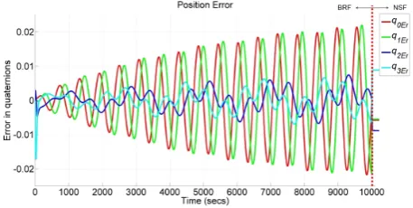
Figure 3: Error between actual and desired quaternions for Manoeuvre A. The dotted line marks the tran-sition from the body reference frame (BRF) to the non-spinning frame (NSF).
Note that in Figure 3 the error in the quaternions
qEris defined as the difference between the actual and desired quaternions at each time-step, and should not be confused with the quaternion error defined in (22). The sail reaches the desired attitude of the body frame with respect to the orbit frame in9.99×103seconds,
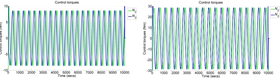
[image:6.595.305.534.440.555.2]Figure 4: Control torques for Manoeuvre A.
the non-spinning frame with respect to the orbit frame has been reached.
Manoeuvre B
In this case the sail was reorientated to a cone angle
α = 35◦ and clock angle δ = 180◦ ((q¯f = [0 −
[image:7.595.73.297.360.473.2]cos 7π/72 0 sin 7π/72]T). The results are shown in Figures 5, 6 and 7.
Figure 5: Angular velocity tracks for Manoeuvre B.
Figure 6: Error between actual and desired quaternions for Manoeuvre B. The dotted line marks the tran-sition from the body reference frame (BRF) to the non-spinning frame (NSF).
VI. DISCUSSION
In the previous section the motion planning method was applied to the reorientation of a simple spinning
Figure 7: Control torques for Manoeuvre B.
disk sail, enabling the sail to achieve a desired attitude without despinning. However from Figures 4 and 7, the required torques are relatively high, of the order
101 N m. This is due to a combination of the
mo-ments of inertia of the solar sail under consideration being particularly high (of the order 105 kgm2), and
the gyroscopic effect of the spinning sail, meaning that large control torques are required to change the sail at-titude. Assuming that there is no offset in the x-axes, the available torques N¯ in the y and z body axes due to an offset between the centre of mass and centre of pressure can be found from:
¯
N = 0ˆi+ (rmpzFSRP x)ˆj−(rmpyFSRP x)ˆk (23)
where rmpy, rmpz are components of the centre of mass to centre of pressure vector r¯mp, FSRP x is the x-component of the SRP force (F¯SRP) and ˆj,kˆ are unit vectors of the body frame. From simulation, the acceleration due to SRP in the x-axis at a distance of 0.24AU from the Sun reached a peak value of 0.0087m/s2. From [7] and [12], the conventionally assumed maximum centre of mass centre of pressure offset lies in the range0.25−0.6%of the characteristic length of the sail. For the140mdiameter sail consid-ered here, this givesr¯mp= [0 0.84 0.84]Tm. Then, for a spacecraft mass of280.77kg,Fsrpx = 2.44N and from (23), the maximum torque available due to the centre of mass centre of pressure offset isNmax=
[0 2.05 2.05]TNm. Manoeuvres A and B clearly vi-olate this torque limit. Therefore the references from the motion planning method in this paper cannot be tracked using the sliding ballast method using an offset of0.25−0.6%of the characteristic length of the sail. From (23), an offset of r¯mp = [0 12.3 12.3]Tm (8.8%of sail diameter) is required to produce a torque of30N m(the maximum torque in Manoeuvres A and B). Considering a system with two translating masses along the y and z body axes, with each mass equal to half the attached mass of the above sail (101.9 kg), the distance the masses would require to move can be found from pg. 791 of [7]:
¯ rc=
ma/2
ms+ma
(0ˆi+ryˆj+rzˆk) (24)
[image:7.595.75.293.531.642.2]the y and z body axes, leads tory=rz= 33.9m. However there are several problems with this approach. Moving masses of this magnitude to a position almost halfway along the radius of the sail would be a con-siderable engineering challenge as motors would have to quickly and accurately reposition the masses. This is unlikely given the magnitude of the masses and the distances involved. Therefore there would likely be considerable delay in achieving the desired position of the masses and hence the required torques. In addition the control torques are dependent on the attitude of the sail and the position of the sail on the orbit, meaning that the value ofFSRP xwill not be constant and so the maximum torques available will vary. If the torques cannot be produced when required, tracking references may be unfeasible. Furthermore, the moments of in-ertia of the spacecraft will change as the large masses move, altering the symmetry and perhaps rendering the references invalid.
The control torques which are required to track the ref-erences could be reduced in a number of ways. These include adding an extra term in the cost function during the parametric optimisation which minimises the con-trol torques, as in [22]. In addition the concon-trol torques could be reduced by increasing manoeuvre time which would further decrease the body rates. However this may cause unacceptable drift from the target orbit dur-ing the reorientation. Finally conventional thrusters could be used to produce the required large control torques, without significant delay, but as stated above the impulsive nature of the torques could excite the sail structure. It will be necessary to implement a re-alistic actuation method, including actuator dynamics, in order to assess the feasibility and practicality of the method.
Figures 3 and 6 show the deviation from the reference tracks throughout the manoeuvres. While these values are small, they are still significant. The accuracy of the method would improve if the attitude of the space-craft in the non-spinning frame could be accurately controlled. At the moment at the end of the manoeuvre the spacecraft is simply brought to a state of pure spin, leading to a drift from the desired attitude. A solution to this may be to find the quaternion differential equa-tions which describe the attitude of the non-spinning frame with respect to the orbit frame, and describe the kinematics of the spacecraft in this way. This would then allow a quaternion component to be included in the control that brings the spacecraft to a state of pure spin, correcting any error in position.
Finally, in order to truly assess the benefits of the method a structural analysis of the spacecraft during the manoeuvre must be carried out. The bending modes of the spacecraft could be found and then compared against the control frequency to ensure that the space-craft structure is not excited, while the bending equa-tions could be integrated alongside the Euler equaequa-tions to assess whether the motion planning method can be used in the face of the errors introduced by a flexing spacecraft.
VII. CONCLUSIONS
This paper has applied a method for generating atti-tude reference motions to a70mradius spin-stabilised disk sail in a heliocentric orbit. The kinematics of the spinning sail were written in terms of the Lie algebra onSU(2)and the optimal Hamiltonian found through application of Pontryagin’s maximum principle. The optimal angular velocities and time evolution of the quaternions were found using Lax Pair integration, en-abling the completely analytical expressions to be para-metrically optimised to produce reference tracks for a given set of boundary conditions.
The method was tested in simulation during two re-pointing manoeuvres related to an inclination change orbital manoeuvre. It was found that while the ref-erences enabled the spinning sail to reach a desired attitude while minimising the body rates, the control torques required were beyond the current technologi-cal limits of sliding ballast or electrochromic control. In addition, the need to bring the sail to a state of pure spin at the end of the manoeuvre resulted in a small er-ror in the final pointing direction.
Future work will see a method implemented to min-imise control torques during the parametric optimisa-tion, and a sliding mass method modelled to assess whether the desired control torques can be feasibly pro-duced. In addition a structural analysis will be car-ried out to determine whether the minimisation of the body rates reduces the impact of the attitude manoeu-vre on the sail structure, justifying the increased control torques that maintaining spin stabilisation throughout requires.
References
[1] Macdonald, M. and McInnes, C.R., ”GeoSail; An enhanced magnetosphere mission, using a small low cost solar sail”, In: Proceedings of the 51st In-ternational Astronautical Congress, Rio de Janeiro, Brazil, October 2000.
[2] Macdonald, M., Hughes, G.W., McInnes, C.R., Lyngvi, A., Falkner, P. and Atzei, A., ”GeoSail: an elegant solar sail demonstration mission”, Journal Spacecraft and Rockets 44 (4), pp. 784-796, 2007a.
[3] Macdonald, M., Hughes, G.W., McInnes, C.R., Lyngvi, A., Falkner, P. and Atzei, A., ”Solar polar orbiter: a solar sail technology reference study”, Journal of Spacecraft and Rockets 43 (5), 960-972, 2006.
[4] Macdonald, M., McInnes, C.R. and Hughes, G.W., ”Technology requirements of exploration beyond Neptune by solar sail propulsion”, Journal of Spacecraft and Rockets 47 (3), 472-483, 2010.
[6] Polites, M., Kalmanson, J. and Mangus, D., ”So-lar sail attitude control using small reaction wheels and magnetic torquers”, Proceedings of the Institu-tion Of Mechanical Engineers Part G - Journal Of Aerospace Engineering, 222(G1), pp.53-62, 2008.
[7] Wie, B., ”Space Vehicle Dynamics and Control,” AIAA Education Series, 2nd addition, 2008.
[8] Wie, B., Murphy, D., ”Solar-sail attitude control design for a sail flight validation mission”, Jour-nal of Spacecraft and Rockets, 44 (4), pp. 809-821, 2007.
[9] Bolle, A., Circi, C., ”Solar sail attitude con-trol through in-plane moving masses”, Journal of Aerospace Engineering, 222 (1), pp. 81-94, 2008.
[10] Scholz, C., Romagnoli, D., Dachwald, B. and Theil, S., ”Performance analysis of an attitude con-trol system for solar sails using sliding masses”, Advances in Space Research, 48, pp. 1822-1835, 2011.
[11] Romagnoli, D. and Oehlschlagel, T., ”High per-formance two degrees of freedom attitude control for solar sails”, Advances in Space Research, 48, pp. 1869-1879, 2011.
[12] Steyn, W.H. and Lappas, V., ”Cubesat solar sail 3-axis stabilization using panel translation and mag-netic torquing”, Aerospace Science and Technol-ogy, 15, pp. 476-485, 2011.
[13] McInnes, C.R., ”Solar Sailing: Technology Dynamics and Mission Applications”, Springer-Praxis, Chichester, 1999.
[14] Funase, R., Shirasawa, Y., Mimasu, Y., Mori, O., Tsuda, Y., Saiki, T. and Kawaguchi, J., ”On-orbit verification of fuel-free attitude control system for spinning solar sail utilizing solar radiation pres-sure”, Advances in Space Research, 48, pp. 1740-1746, 2011.
[15] Sidi, M.J., ”Spacecraft Dynamics and Control: A practical engineering approach”, Cambridge Uni-versity Press, 2002.
[16] Scrivener, S.L. and Thompson, R.C., ”Survey of Time-Optimal attitude Maneuvers”, Journal of Guidance, Control, and Dynamics, 17(2), pp. 225-231, 1994.
[17] Vadali, S.R. and Junkins, J.L., ”Optimal open loop and stable feedback control of rigid spacecraft attitude maneuvers”, Journal of Astronautical Sci-ences, 32(2), pp. 105-122, 1984.
[18] Tsiotras, P., ”Stabilization and Optimality Re-sults for the Attitude Control Problem”, Journal of Guidance Control and Dynamics, 19(4), 1996.
[19] Bilimoria, K.D., Wie, B., ”Time-optimal three-axis reorientation of a rigid spacecraft”, Journal of Guidance, Control, and Dynamics, 16(3), pp. 446-452, 1993.
[20] Seywald, H., Kumar, R.R., Deshpande, S.S. and Heck, M.L., ”Minimum fuel spacecraft reorianta-tion”, Journal of Guidance, Control, and Dynam-ics, 17(1), pp. 21-29, 1994.
[21] Lawton, J., Beard, R. and Mclain, T., ”Suc-cessive Galerkin approximation of nonlinear opti-mal attitude control”, Proceedings of the American Control Conference, San Diego, California, June, 1999.
[22] Biggs, J. and Horri, N., ”Optimal geometric mo-tion planning for spin-stabilized spacecraft”, Sys-tems and Control Letters, 61 (4), pp. 609-616, 2012.
[23] Bate, R.R., Mueller, D.D. and White, J., ”Funda-mentals of Astrodynamics,” Dover Books, pp. 13, pp. pp. 156-159, 1971.