Incremental ECAP of thick continuous plates -
machine and initial trials
A Rosochowski1 and L Olejnik2
1 Reader, University of Strathclyde, Glasgow, UK
2 Senior Lecturer, Warsaw University of Technology, Warsaw, Poland E-mail: [email protected]; [email protected]
Abstract. Incremental ECAP (I-ECAP) can be used for SPD of continuous bars, plates and sheets. This paper describes design, construction and preliminary trials of a prototype machine capable of processing thick continuous plates. To increase productivity, a two-turn I-ECAP is used, which is equivalent to route C in conventional one-turn ECAP. The machine has a reciprocating punch inclined at 45°, a clamp holding the plate in the die during deformation and a feeder incrementally feeding the plate when it is not deformed; all these devices are driven by hydraulic actuators controlled by a PLC. The machine is capable of deforming materials at room temperature as well as elevated temperatures. The die is heated with electric heaters. The machine has also an integrated cooling system and a lubrication system. The material used for the initial trials was Al 1050 plate (10501000) conversion coated with calcium aluminate and lubricated with dry soap. The process was carried out at room temperature using 1.6 mm feeding stroke and a low cycle frequency of approximately 0.2 Hz. The UFG structure after the first pass of the process revealed by STEM confirms process feasibility.
1. Introduction
[image:1.595.67.521.494.713.2]The process of incremental equal channel angular pressing (I-ECAP) was proposed in 2005 and first described in 2007 [1]. It was invented as an extension of ECAP to enable processing of continuous billets such as bars [2], plates [3] and sheets [4]. It is known that feeding of long billets into a classical ECAP die is problematic if attempted using only the friction forces [5]. Therefore I-ECAP decuples the feeding and deformation stages by feeding a billet incrementally and synchronically with a reciprocating punch as shown for one-turn channel in Fig. 1.
Fig. 1 Schematics of I–ECAP with one-turn and two-turn channel.
In order to decrease the number of ECAP passes, required to accumulate high strain, the classical ECAP process was modified to incorporate a channel with two turns [6], which is equivalent to route C (180° rotation about billet axis) between consecutive passes of ECAP with one turn channel. In the recent years, this idea has been explored under different names, for example, S-type ECAP [7], two-turn ECAP [8] and ECAP in parallel channels [9]. The concept of I-ECAP using a two-turn channel was analysed in [10]. Fig. 1 shows the tool configuration in this case, with a stationary die and a stationary (or reciprocating) clamp. The billet is fed incrementally and synchronically with the reciprocating punch. The billet material is subjected to simple shear twice, as indicated by the dashed zones at the first and the second turn of the channel. The finite element analysis proved feasibility of the two-turn version of I-ECAP [10]. It has been shown that, for the appropriate tool geometry and process parameters, the new version of I-ECAP enables obtaining a well defined and uniform strain distribution. This, together with the improved productivity and the ability to process continuous billets, should make it an interesting option for industrial applications. Comparing to bars, plates have much larger volume so severe plastic deformation (SPD) of plates would increase productivity. The current paper reports the design, engineering and testing effort put into building a prototype machine, which would be able to process thick continuous plates using a two-turn I-ECAP.
2. Machine
The design specification for the new machine assumed the cross section of the processed
plate to be 10 mm 50 mm and the length to be unlimited (for practical reasons the length
[image:2.595.119.463.470.702.2]used was 1000 mm). To be able to process long plates, the plate was to be fed horizontally, then turn down vertically and finally turn again to leave the die horizontally as shown in Fig.2. The angles of these turns were both 90°. The offset of the input and output channel axes was 15 mm and the radii were equal to 2 mm and 4 mm. To deform the material in the same way at both channel turns, the punch was to move at an angle of 45°.
Fig. 2 Geometry of the channel.
Clamp
Punch
Die
Input
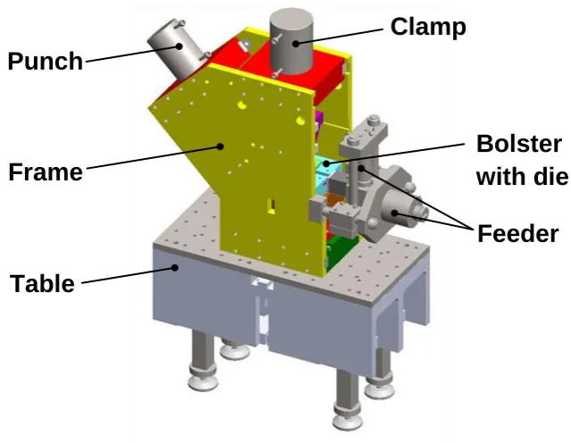
The die was supported by a massive bolster, which could be moved into position by sliding it between two side plates of the machine frame. The same frame supported the punch, the clamp and the material feeding systems. All these systems, together with a table, are shown in Fig. 3. Functionally, all the systems involving machine movements had to be synchronised. The feeder would not be capable of bearing the process force during the punch deformation stage, therefore, a clamp was adopted to close the die and provide the required support for the plate. On punch withdrawal, the clamp would be released to enable feeding the plate.
Following this design, the machine was built with the intension to prove the concept of the process and test its industrial feasibility (Fig. 4a). The punch and the clamp were driven by two hydraulic actuators with the capacity of 800 kN and 1000 kN respectively. The feeder also used two actuators, a vertical one for clamping the plate and a horizontal one to move it forward. Thus the machine required four hydraulic actuators, which were supplied with oil by four hydraulic pumps fed from a single hydraulic tank (Fig. 4b). Synchronising the work of four actuators required several displacement and hydraulic pressure sensors providing information for a PLC unit located in a control cabinet (Fig. 4c). The cabinet pulpit served as a machine-user interface (Fig. 4d). An additional PC-based data acquisition system was used to record all relevant data with high resolution. The machine was intended for room temperature as well as for elevated temperatures (up to 300°C) to enable processing a variety of metals. The bolster system was equipped with a number of electric heaters and thermocouples positioned at important locations in the bolster and the die. A separate multichannel system enabled precise control of temperature. To avoid overheating of the machine, there was a closed circuit water cooling system incorporating cooling channels and a chiller. There was also a lubricating system, which supplied lubricant to the material deformation zone.
Punch
Feeder
Clamp
Fig. 3 Main systems of the I-ECAP machine for plates.
Bolster
with die
Frame
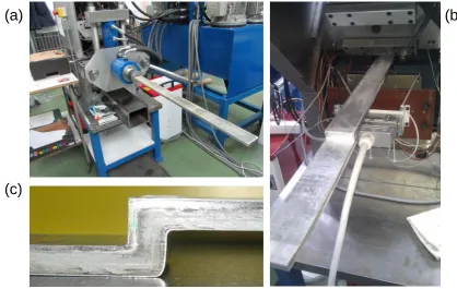
[image:3.595.135.455.233.481.2]Fig. 5 I-ECAP machine for plates in action: feeding of plate (a), receiving processed plate (b) and deformation zone (c).
(a)
(c)
[image:4.595.81.500.438.703.2](b)
Fig. 4 I-ECAP machine for plates (a), hydraulic power pack (b), control cabinet (c) and its pulpit (d).
(a)
(c)
(d)
3. Test results
The material used for the initial trials was Al1050 plate (10501000) conversion coated
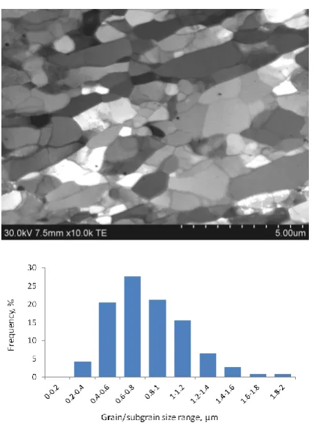
[image:5.595.189.417.259.571.2]with calcium aluminate and lubricated with dry soap. The process was carried out at room temperature using 1.6 mm feeding stroke and a low cycle frequency of approximately 0.2 Hz. Fig. 5a illustrates the plate being fed to the machine while Fig. 5b shows the plate partly processed and moved forward for inspection of the deformation zone (Fig. 5c). The UFG structure after the first pass of the process revealed by STEM confirms process feasibility. Fig. 6 displays this structure for the plane normal to plate axis. The grain size distribution in this plane and the average grain size o 0.83 micron is what one could expect from route C after two passes of classical ECAP for this material.
4. Conclusions
The concept of I-ECAP has been successfully implemented on a semi-industrial scale by designing and building a machine capable of refining grain structure in thick continuous
plates with a 10 mm 50 mm cross section. For the first time such a process was used for two
turns of the channel doubling the value of the strain achieved in one pass and increasing productivity. The first test was carried out at room temperature so the next series of experiments will be about using an aluminium alloy rather than pure aluminium in order to test machine's capability at elevated temperatures; the first heating trial has successfully increased the plate temperature to 200°C, on its way through the die towards the deformation zone. The initial tests carried out so far have provided invaluable information
regarding possible improvements, which will gradually be implemented in order to create an efficient and robust machine suitable for industrial applications.
References
[1] Rosochowski A and Olejnik L 2007 Proc. of 10th Int. Conf. on Material Forming,
Esaform (Zaragoza) (American Institute of Physics) vol 907 p 653
[2] Rosochowski A, Olejnik L and Richert M 2008 Mater. Sci. Forum, 584–586 139
[3] Olejnik L, Rosochowski A and Richert M 2008 Mater. Sci, Forum, 584–586 108
[4] Rosochowski A, Rosochowska M, Olejnik L and Verlinden B 2010 Proceedings of 13th Int.
Conf. on Metal Forming (Toyohashi) Steel Research International81/9 470
[5] Segal V M 2010 J. Mater. Process. Tech. 210 542
[6] Shchukin V Ya and Segal V M 1976 Device for strengthening materials by pressure
U.S.S.R patent SU 515968.
[7] Liu Z Y, Liang G X, Wang E D and Wang Z R 1998 Mater. Sci. Eng. A 242 137
[8] Rosochowski A and Olejnik L 2002 J. Mater. Process. Tech.125–126 30
[9] Raab G I 2005 Mater. Sci. Eng. A 410-411 230