ContentslistsavailableatScienceDirect
Journal
of
Manufacturing
Systems
jo u r n al ho m e p a g e :w w w . e l s e v i e r . c o m / l o c a t e / j m a n s y s
A
geometrical
model
for
surface
roughness
prediction
when
face
milling
Al
7075-T7351
with
square
insert
tools
Patricia
Mu ˜
noz-Escalona
a,∗,
Paul
G.
Maropoulos
b aUniversityofStrathclyde,DepartmentofMechanicalandAerospaceEngineering,Glasgow,UK bUniversityofBath,DepartmentofMechanicalEngineering,Bath,UKa
r
t
i
c
l
e
i
n
f
o
Articlehistory:
Received13February2012
Receivedinrevisedform16June2014 Accepted18June2014
Availableonlinexxx
Keywords:
Facemilling Surfaceroughness Taguchi Toolrunouts
a
b
s
t
r
a
c
t
Surfacequalityisimportantinengineeringandavitalaspectofitissurfaceroughness,sinceitplaysan importantroleinwearresistance,ductility,tensile,andfatiguestrengthformachinedparts.Thispaper reportsonaresearchstudyonthedevelopmentofageometricalmodelforsurfaceroughnessprediction whenfacemillingwithsquareinserts.Themodelisbasedonageometricalanalysisoftherecreationof thetooltrailleftonthemachinedsurface.Themodelhasbeenvalidatedwithexperimentaldataobtained forhighspeedmillingofaluminumalloy(Al7075-T7351)whenusingawiderangeofcuttingspeed,feed pertooth,axialdepthofcutanddifferentvaluesoftoolnoseradius(0.8mmand2.5mm),usingthe Taguchimethodasthedesignofexperiments.Theexperimentalroughnesswasobtainedbymeasuring thesurfaceroughnessofthemilledsurfaceswithanon-contactprofilometer.Thedevelopedmodelcan beusedforanycombinationofmaterialworkpieceandtool,whentoolflankwearisnotconsidered andissuitableforusinganytooldiameterwithanynumberofteethandtoolnoseradius.Theresults showthatthedevelopedmodelachievedanexcellentperformancewithalmost98%accuracyinterms ofpredictingthesurfaceroughnesswhencomparedtotheexperimentaldata.
©2014TheSocietyofManufacturingEngineers.PublishedbyElsevierLtd.Allrightsreserved.
1. Introduction
Productqualityhasalwaysbeenoneofthemostimportant ele-mentsinmanufacturingoperations.Inviewofthepresentglobal economyandcompetition,continuousimprovementinqualityhas becomea major priority, particularlyfor major corporationsin industrializedcountries,suchasUSA,UK,Germany,Japan,etc.The rangeoftechnologiesinvolvedinthemanufacturingsector con-tinuestogrowwiththeintroductionofimprovedequipmentand toolsinordertoproducehighqualityfinalproducts,withspecific characteristics,suchas:dimensionalaccuracy,surfaceroughness, etc.Machiningprocessesrequirespecificattentiontoguaranteethe qualityofafinalproductagainstcertainmanufacturing specifica-tions.Besidestheobviousproblemsrelatedtocorrectdimensions, oneofthebiggestproblemsisachievingtheappropriatefinishor surfacesmoothnessontheworkpiece.Surfacesarecommercially andtechnologicallyimportantforanumberofreasons.Few rea-sonsare:(1)esthetic; asmooth andfreeofscratches surfaceis morelikelytogiveafavorableimpressiontocostumer,(2)surfaces affectsafety,(3)surfacesinteractwithitsenvironment,duetoits
∗Correspondingauthor.
E-mailaddress:[email protected](P.Mu ˜noz-Escalona).
influenceonmechanicalpropertiessuchas:wear,corrosionand lubrication[1–5].
General defectscaused by and produced during component manufacturingcanberesponsibleforinadequatesurfaceintegrity. These defects are usually caused by a combination of factors, such as defectsin theoriginal material, themethod by which the surface is produced, and lack or proper control of process parameters that can result in excessive stresses and tempera-ture. For example, roughness is a measure of the texture of a surface and is a consequence of the cutting parameters, tool geometry,etc.usedduringthemachiningprocess.Dependingon how rough the surface is (deepnessof thegrooves left by the tool onthe machined surface) a piece can wear more quickly and have higher friction coefficients than a smoother surface [6].
Oneofthemostpromisingadvancedmanufacturing technolo-giesinthelastdecadeisthehighspeedcutting,duetoitspotential forfasterproductionrates,shorterleadtimes,reducedcostsand improvedpartquality,since thetechniquecombines high spin-dlespeeds withincreased feedrates [7].This resultsin a high chip-formingrateandlowermillingforces,producinganimproved surfacequalityandtightertolerances.However,appropriatetools andcuttingparametersshouldbeusedinordertocompletethe machiningprocesswithoutdamagingthecuttingtool.Thisisthe
http://dx.doi.org/10.1016/j.jmsy.2014.06.011
Nomenclature
ap axialdepthofcut(mm) εa axialrunout(mm) εr radialrunout(mm)
fz feedpertooth(mm/rev*tooth) HBN Brinellhardnessnumber i toothnumber
n peaknumberofthesurfaceroughnessprofile r toolnoseradius(mm)
Ra experimentalsurfaceroughness(m) Rap predictedsurfaceroughness(m) %RE relativeerror(%)
Su maximumstrength(MPa) Sy yieldstrength(MPa) V cuttingspeed(m/min)
mainfactorofwhythepredictionandcontrolofthesurface rough-nessandthetoolweararechallengestoresearchers.
Inrecentyearstherehavebeenseveralproposalsregarding dif-ferentmodelsforsurfaceroughnesspredictionsduringamilling process.
Baeketal.[8]analyzedtheeffectsoftheinsertrunouterrorsand thevariationofthefeedrateonthesurfaceroughnessoperations usingasurfaceroughnessmodel.Theexperimentswereconducted inAISI1041ductilesteel.
In2004,Wang[9]analyzedtheinfluenceofcuttingconditions andtoolgeometryonthesurfaceroughnesswhenslotendmilling aluminumalloy2014-T6.Thedevelopedsurfaceroughness mod-elsforbothdrycuttingandcoolantconditionswerebuiltusinga responsesurfacemethodology(RSM).Theresultsshowedthatthe dry-cutroughnesswasreducedbyapplyingcuttingfluid.
Theresearch madeby Franco etal. [10],contributes onthe developmentofanumericalmodelforsurfaceroughnessprofile predictionwhenusingroundinserts.Themodelrelatesthefeed, thecuttingtoolgeometryandthetoolerrors,incorporatingan algo-rithmthatmakespossiblethevariationofthesurfaceroughness fromthevaluesthatcanbeadoptedbythetoolerrors.
Researcher,Oktemaetal.[11],predictedthesurfaceroughness byusingRSM(responsesurfacemethodology)coupledwithGA (geneticalgorithms).ThestudiesweremadeinAl7075-T6.
In2005,Reddyetal.[12]studiedtheeffectoftoolgeometry (radialrakeangleandtoolnoseradius)andcuttingconditions (cut-tingspeedandfeedrate)onthemachiningperformanceduringend millingofmediumcarbonsteel.Firstandsecondorder mathemat-icalmodels,intermsofmachiningparametersweredevelopedfor surfaceroughnesspredictionusingRSM.Theresultsshowedthat thecuttingspeed,thefeed,theradialrakeangleandthetoolnose radiusaretheprimaryfactorsinfluencingthesurfaceroughnessof mediumcarbonsteelduringendmillingprocesses.
Thestudyofplanesurfacegenerationmechanisminflatend millingprocesswasmadebyRyuaetal.[13].Theyconcludedthat thebottomofaflatendmillinghasanendcuttingedgeanglethat playsanimportantroleinsurfacetextureandthatthesurface tex-tureisproduced bysuperpositionofconical surfacesgenerated bytheendcuttingedgerotation.Theevaluationofthegenerated surfacetexturecharacteristicwasdoneusingRSM.
AlsoOzcelik[14]in2006,presentedthedevelopmentofa sta-tisticalmodelforsurfaceroughnessestimationinahigh-speedflat endmillingprocess,underwetcuttingconditions,using machin-ingvariablessuchasspindlespeed,feedrate,depthofcutandstep over.
Researcher,Jesuthanametal.[15],proposedthedevelopmentof anovelhybridneuralnetwork(NN)trainedwithgeneticalgorithm
(GA)andparticleswarmoptimization(PSO)forthepredictionof surfaceroughness.TheproposedhybridNNwasfoundtobe com-petentin termsof computationalspeedand efficiencyoverthe NNmodel.In2007,Zhangetal.[16]studiedtheTaguchidesign applicationtooptimizethesurfacequalityofafacemilling opera-tionwhenusingaCNC.TheresultsverifiedthattheTaguchidesign wassuccessfullyinoptimizingthemillingparametersforsurface roughness.
BharathiandBaskarin2012[17]developedageneralizedmodel basedonparticleswarmoptimization(PSO)techniquetoachieve a desired surface roughness when face milling aluminum. The machiningtimewasincludedasinputparametertogetherwith cuttingspeed,feedanddepthofcut.Theyconcludedthattheuse ofoptimizationtechniquereplacestheselectionofcutting param-etersbytrialanderrormethod.
Finally,Arrazolaetal.in2013[18]compileddifferentadvances inthemodelingofmachiningprocesses.Initspapertheadvancesin predictive,analytical,computationalandempiricalmodelsamong othersforthepredictionofvariablessuchassurfaceroughness, cuttingforces,stresses,chipformation,etc.arehighlighted.
Fromanalyzingalltheliterature,ithasbeenobservedthatthe proposedmodelsarebasedoncomputational,numericalanalysis andcomplexmathematicalcalculusandbasicallyaddressestheuse ofendmillingprocessesforroundinsertswhenusingafacemilling processwithaspecificnumberofteethandtooldiameter.Based onthesefindings,theaimofthisresearchistodevelopamodel forsurfaceroughnesspredictionbasedsolelyongeometrywhen facemillingwithsquareinserts.Themodelcanbeusedforanytool geometryregardingtoolnoseradius,tooldiameterandnumberof teeth,wherealsoparameterssuchasthefeedpertoothandtoolrun outsareconsidered.Thevalidationofthemodelwillbeconducted byusingexperimentalsurfaceroughnessdataobtainedwhenface millingaluminumalloy7075-T7351underspecificcutting condi-tions.
This newcontribution will represent a useful capability for researchersintheareasinceitwillallowthepredictionof rough-nessbeforeconductingtrialanderrorexperiments,representing savingincostandtime.
2. Developmentofthegeometricalmodelforsurface roughnessprediction
Theproposedgeometricalmodelisdevelopedbasedona geo-metrical analysis. In this case, a visual observation of the Al 7075-T7351machinedsurfaceisconductedandarecreationofthe tooltrailleftonthemachinedsurfaceisanalyzed.Inthiscasethe tooltrailisdevelopedconsideringthefeedpertooth,thecutting toolnoseradiusandthetoolrunouterrors.Frompreviousresearch [8,10]itwasnotedtheinfluenceofthetoolrunoutvariableonthe surfaceroughnessandtheimportanceofincludingthisvariablefor thepredictionofthesurfaceroughness.
Thetoolrunouts(axial(εa)andradial(εr)deviationsofthe tool)aredefectsthat consistinsmalldiscrepancies inthe rela-tivepositionofthedifferentcuttingteeth.Thesediscrepanciesare obtainedformanyreasonssuchas:manufacturingtolerancesofthe cuttingtoolinsertsandseats,inaccuracyinthefixtureofthe index-ableinserts,uncertaintyintheclampingforceoftheinsertscrews, imperfectionsinthemachinetoolaxismovement,etc.[10].
Fig.1showsaschematicofthetoolrunoutsandangleKiand Fig.2showsthecontributionofthetoolrunoutsonthesurface roughnessprofile.
Fig.1.Schematicoftheaxial(εa)andradial(εr)deviationduringrotationofthe
toolandangle,Ki.
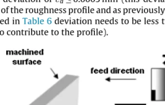
consequentlythevalueofsurfaceroughness.Theradialtool devi-ationproducesasmallmovementoftheprofileina“rightorleft” direction(dependingonthesignofthedeviation)anditdoesnot affecttheheightoftheprofile.
Inthegeometricalmodelatwoteethcuttingtoolisconsidered, tooth(i)isconsideredthepatternwith(εa=εr=0)andtooth(i+1) willhave(εa =/ εr =/ 0).
Inordertosimplifythemodelthebackcuttingprocesswillnot beconsidered.Alsodespitetheinfluenceoftoolwearonsurface roughnessthisvariableisnotincludedinthemodelsince:(1)new insertsareemployedduringeachtrial,(2)thelengthofcutused forthemillingprocessissmall(333.3mm),(3)themilling pro-cesswasconductedunderMQL(MinimumQuantityLubrication), (4)theinclusionoftoolwearwouldrequireamuchlongertime forexperimentsandahigherbudget,consideringitacompletely separatestudy,outsidethescopeofthisresearch.
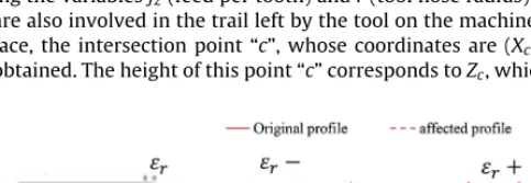
Fig.3showsaschemeofthetrailleftbythecuttingtoolonthe machinedsurface,wheretheroughnessprofileisobserved.Inthis casetooth(i)isrepresentedbythickcontinueslineandtooth(i+1) isrepresentedbythickdashline.
WhenanalyzingthisFig.3,whichisthestartingpointforthe developmentofthemodel,itisobservedthatasthetoolmoves alongthecuttinglength,tooth(i)startstocut(thickcontinuesline) andthentooth(i+1)(thickdashline)whichisfzawayfromtooth (i)startstocutaswell.Asobserved,sincetheinsertsselectedfor thecuttingprocesshaveasquaregeometry,theyarecomposedof twosections.Thefirstsectionisdelimitedbyacirclesection(tool’s noseradius)andthesecondsectionisdelimitedbyaline(giving shapetoasquarewithroundcorners).
Bytakingintoaccounttheintersectionofthesectionofthecircle (negativesize,∪)andthesectionoftheline,andbyalso consider-ingthevariablesfz(feedpertooth)andr(toolnoseradius)which arealsoinvolvedinthetrailleftbythetoolonthemachined sur-face,theintersectionpoint“c”,whosecoordinatesare(Xc,Zc)is obtained.Theheightofthispoint“c”correspondstoZc,whichalso
Fig.2.Illustrationofhowthe2Dsurfaceroughnessprofileisaffectedwhen consid-ering“+”or“−”toolrunouts.
corresponds to the surface roughness value (predicted by the model).Thispoint“c”(intersectionbetweenthecircle(tool’snose radiusfromtooth(i)andthelineofthetool’sshapefromtooth (i+1)))isrepeatedalongthemachinedsurface,definingthe sur-faceroughnessprofile(shadedareainFig.3).Itmustbehighlighted thatthisheight(Zc),changesdependingontheaxialtoolrunouts deviationsthatareconsideredforeachofthetool’steeth.
AlsoFig.3showstheparametersthatareusedtodeterminethe surfaceprofile.Asitisobservedthefigureincludesthepositionof tooth(i)andtooth(i+1),aswellasthemarksleftbytheteeth, denotedas“n”and“n+1.Itmustbehighlightedthatthesemarks dependsonthepositionoftheteeth.
Eq.(1)presentsthenegativepartofthesquarerootofthe cir-cleequation,whichinthiscaseisthepartofthecirclethatitis consideredforthedevelopmentofthemodel(∪).
Z=Zn−
r2−(X−X
n)2 (1)
whereXnandZnvaluesarethecoordinatesofthecenterofthecircle (thatformsthetool’snoseradius).
Formark“n”thesecoordinatesare:
Xn=nfz+εri (2)
Zn=r+εai (3)
Formark“n+1thesecoordinatesare:
Xn+1=(n+1)fz+εri+1 (4)
Zn+1=r+εai+1 (5)
WhenanalyzingFig.3itisobservedthatthepointsthatneedto beconsideredfortheroughnessprofilearepoint“a”andpoint“c”, asthesepointswillappearalongtheroughnessprofileduringthe cuttingprocess.
Point“a”coordinatesare:
Xa=(n+1)fz+εri+1 (6)
Za=εai+1 (7)
Aspreviouslymentionedpoint“c”definestheheightofthe pro-fileandasobservedwhenanalyzingFig.3thispointisobtained throughtheintersectionofthecirclesectionthatcorrespondsto tool’snoseradiusoftooth(i)andthelinearsectionoftooth(i+1). ThesecoordinatesarenamedXcandZc.Theintersectionpointis obtainedby equating theequationof a circle (Eq.(1))and the equationofalinewhichisreportedinEq.(8).
ZL=mXL+b (8)
whereZLiscoordinateZatanypointofthelinewithaXLcoordinate, XLiscoordinateXatanypointofthelinewithaZLcoordinate,mis slope,andbisinterceptionwithZaxis.Inthiscasetheinterception willgiveZcoordinateofpointb,namedZb.
Eq.(9)reportstheequationoftheslope
m=−tan(Ki+1) (9)
WhensubstitutingEq.(9)inEq.(8)andconsideringXL=Xaand ZL=Zathenthecuttingpoint“b”withtheZaxisisobtainedand showninEq.(10)whereaspreviouslymentionedb=Zb.
Zb=[(n+1)fz+εri+1)]·tan(Ki+1)+εai+1 (10)
Whensubstituting Eqs.(10) and (9) in Eq. (8) thefollowing is obtained.
ZL=−tan(Ki+1)·[X−((n+1)fz+εri+1)]+εai+1 (11)
[image:3.646.72.262.57.215.2] [image:3.646.50.292.637.721.2]Fig.3. Schemeofthetrailleftbythecuttingtoolwheretheroughnessprofilecanbeobserved.
ToobtainZccoordinate,whichallowsthegenerationofthe2D profile,thisoneisdefinedbyEq.(13),whichasobserved,is com-posedbytwoexpressions13aand13b.
Eq.(13a)correspondstotheequationofthecircle,whichisused tocalculateZcwhen“X”isbiggerthen“Xn”(Eq.(2)),butsmalleror equalto“Xc”(Eq.(12)).
Eq.(13b)correspondstotheequationofaline,whichisused tocalculate“Zc”when“X”isbiggerthen“Xc”(Eq.(12))butsmaller than“Xn+1”(Eq.(4)).Itmustbehighlightedthattheseequations
wereobtainedbyusingtheMathCadsoftwareversion14.
Xc=
−[m(Zb−Zn)−Xn]+
[m(Xb−Zn)−Xn]2−(m2+1)·[(Zb−Zn)2+Xn2−r2]
(m2+1)
(12)
Zc(X,i,n)
r+εai−r2−[X−(nf
z+εri)]
2
∀
nnfz+εri≤X≤Xc (13a) −tan(Ki+1)·(X−((n+1)fz+εri+1))+εai+1
∀
nXc<X≤(n+1)fz+εri+1 (13b)(13)
Itmustbehighlightedthatthedevelopedmodelisvalidforthe averagesurfaceroughnessdowntothecenterofthefacingpass, wherethecenterisdefinedbythepaththattheaxisofrotationof thetooltakesacrossthesurface.
3. Experimentalprocedureforthevalidationofthe developedgeometricalmodelforsurfaceroughness prediction
Oncethemodelwasdeveloped,thiswasvalidatedby compar-ingthepredictedvaluesofsurfaceroughnessobtainedfromthe modelwithexperimentalvaluesobtainedwhenfacemilling alu-minumalloy7075-T7351sampleswiththefollowingdimensions, 333.3mm×76.2mm×31.75mm.
Theselectionofthismaterialwasbasedonitsimportancein theaerospaceindustrydue toitshightoughnesscharacteristic, beenwidelyusedwherelowweightisneededsuchasinplates, sheetsandextrusionsofairframes.Theselectionofsquareinserts istoimprovepredictionmethodstoestimatesurfaceroughnesson facemillingpartswhenusingthisinsertgeometryandinaddition, squareinsertsalsoallowshouldercuts.
Tables1and2showthechemicalcompositionandthe mechan-icalpropertiesofthisAl7075-T7351respectively.
AsacuttingtoolstandardinsertholderofØTool=32mm,with
two(2)teethwasused.Twotypesofuncoatedindexableinserts,
Table1
ChemicalcompositionofAl7075-7351.
%Al±0.1 %Cr±0.007 %Cu±0.013 %Mg±0.381 %Zn±0.020
87.1 0.174 1.586 2.693 5.240
Varianspectrophotometer.ModelAA-275(weightpercentage).
SDHT 120508FR-ALP CWK26 and SDHT 120525FR-ALP CWK26 wereusedfortheexperimentswherethefirstonecorrespondsto 0.8mmoftoolnoseradiusandthesecondto2.5mmoftoolnose radius.Thistypeofinsertwasrecommendedbythetoolsupplier forthemachiningofaluminumalloyunderawetcuttingoperation. Fig.4showsaschemeoftheinsertgeometryusedforthisstudy.
AssuggestedbyDinizandFilho[19],inordertoachieveabetter performanceofthetool(longertoollife)byremovingthematerial injustonesinglepassthefollowingconditionsmustbeapplied:(1)
Table2
MechanicalpropertiesofAl7075-T7351.
Su(MPa) 593
Sy(MPa) 448
HBNa 135
aLoad500kgandØ
ball=10mm.
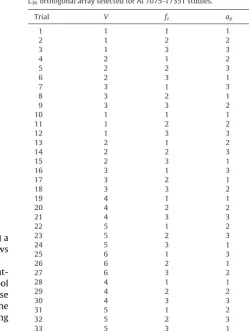
[image:4.646.115.473.59.252.2] [image:4.646.300.557.302.329.2]Fig.5. Schemeofthecuttingprocessusedinthisstudy.
ØTOOL>workpiecewidth;inourcase,32mm>31.75mmand(2)a
symmetricpositionofthetoolagainsttheworkpiece.Fig.5shows aschematicofthecuttingprocess.
Thecuttingparametersselectedforthis studywerethe cut-tingspeed,thefeedpertooth,theaxialdepthofcutandthetool noseradius,sincefrompreviousresearchitwasobservedthatthese variableshadthehighestinfluenceonthesurfaceroughnessofthe workpiece[20–22].Table3showsthevaluesoftheselectedcutting parameters.
AsobservedfromTable3,six(6)levelswereselectedforthe cuttingspeed,three(3)levelsforthefeedpertoothandaxialdepth ofcutandtwo(2)levelsforthetoolnoseradiusparameter.
ADeckelMaho,DMV50 evolution,CNC, highspeedvertical machine center, witha maximum spindlespeed of 18,000rpm wasusedfor thefacemillingoperation. Allthetestswere con-ductedunderminimumquantityoflubricant(MQL),since:(1)tool wearwasnotconsideredasacriterionthatwillaffecttheresultof thecuttingprocessduetothesmallamountofmaterialthatwas removedfromtheworkpiece,(onesinglepassof333.3mm),(2) newinsertswereusedforeachtrialand(3)thismaterialneeded tobecutunderaMQLcuttingcondition.
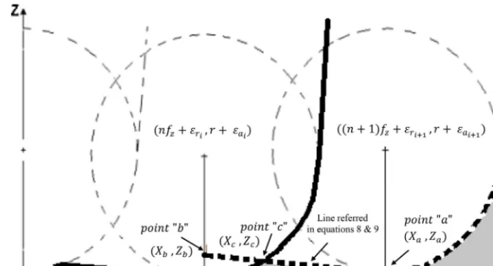
Forthedesignofexperiment(DoE),theTaguchimethodwas applied.Thismethodusesaspecialdesignoforthogonalarray(OA) tostudytheentireparametersspacewithonlyafewnumbersof experiments.TheselectionoftheappropriateOAisbasedonthe followingcriteria:thenumbersoffactorsandinteractionof inter-est,thenumbersoflevelsforthefactorsofinterestandthedesired experimentalresolutionorcostlimitation[23].InthisstudyaL36
mixedleveldesign (L36=61.32.21)wasselected.Table4shows
theorthogonalarrayselectedforthestudy,wherenumbers1–6 representthelevelsofeachcuttingvariable.
Oncethespecimensweremachinedtheywereputonabench forsurfaceroughnessmeasurement.Thesurface roughnesswas measuredacrossthedirectionofthemachinedsurfacelay(feed
Table3
Selectedcuttingparametersforthestudy.
Level V(m/min) fz(mm/rev.tooth) ap(mm) r(mm)
1 600 0.1 3.0 0.8
2 800 0.2 3.5 2.5
3 1000 0.3 4.0 –
4 1200 – – –
5 1400 – – –
6 1600 – – –
Table4
L36orthogonalarrayselectedforAl7075-T7351studies.
Trial V fz ap r
1 1 1 1 1
2 1 2 2 1
3 1 3 3 1
4 2 1 2 1
5 2 2 3 1
6 2 3 1 1
7 3 1 3 1
8 3 2 1 1
9 3 3 2 1
10 1 1 1 2
11 1 2 2 2
12 1 3 3 2
13 2 1 2 2
14 2 2 3 2
15 2 3 1 2
16 3 1 3 2
17 3 2 1 2
18 3 3 2 2
19 4 1 1 1
20 4 2 2 1
21 4 3 3 1
22 5 1 2 1
23 5 2 3 1
24 5 3 1 1
25 6 1 3 1
26 6 2 1 1
27 6 3 2 1
28 4 1 1 2
29 4 2 2 2
30 4 3 3 2
31 5 1 2 2
32 5 2 3 2
33 5 3 1 2
34 6 1 3 2
35 6 2 1 2
36 6 3 2 2
direction)usinganon-contact whitelampprofilometer ProScan 2000andfollowingASMEB46.1standards.
Theroughnessaveragevalueofeachspecimenwasdetermined bymeasuringthreeareas(lineroughnessaveragemeasurement), locatedinthecenterofthespecimen,specifically,8cmawayfrom theedgeoftheworkpieceandjustwherethevicewasretaining theworkpiece.Theideaofmeasuringtheroughnessatthe work-piececenter,wasinordertomakesurethattheobtainedvaluesof surfaceroughnesswerenotaffectedbypossiblevibrationsdueto theimpactofthetoolenteringtheworkpiece.Thenanaverageof thesethreevalueswasusedtorepresenttheexperimentalsurface roughnessvalueofthespecimen(Ra).Thesurfaceroughnessvalues measuredwithinthemeasuringareaaresufficienttorepresentthe roughnessofeachworkpiece[24].
Inthiscasestudy,thesamplesizefortheRameasurementwas 4mmintheXdirectionand4mmintheYdirection.Inorderto coverthis4mm×4mmarea,atotalof1335stepswithasizeof 0.003mmanda0.8mmforcut-offwavelength.Oncemeasuringthe roughnessaftertheseconditions,thewavinessfilterwasapplied andthefinalroughnessofvalue(Ra)wasreported.Theselection ofapropervalueofcut-offwavelengthisimportantasthis fac-tordetermineswhichwavelengthbelongstowavinessandwhich belongstoroughness.Thevalueselectedforthemeasurementswas suggestedbythemanufacturer’suser’sguideprofilometerProScan 2000.Besidesthethreevaluesofsurfaceroughnessobtainedfrom themachinedsurfacebyusingtheProScan2000,the2Dsurface roughnessprofilewasalsoobtained(Fig.6andTable5).
Therelativeerrorbetweentheexperimentalvalueandthe pre-dictedvaluewascalculatedusingEq.(14).
%RE=
Ra−Rap Ra [image:5.646.97.242.58.247.2] [image:5.646.311.561.72.403.2]Table5
Experimentalandpredictedvaluesofsurfaceroughness,radialεrandaxialεa devi-ations,angleKiand%RE.
Trial Ki(◦) εr(mm) εa(mm) Ra±0.001
(m)
Rap±0.001 (m)
%RE
1 0.40 0.009 0.0002 0.699 0.686 1.9 2 0.29 0.001 0.0002 1.017 1.014 0.3 3 0.28 0.009 0.0002 1.472 1.473 0.1 4 0.39 0.002 0.0002 0.679 0.671 1.2 5 0.24 −0.009 0.0002 0.838 0.846 1.0 6 0.12 −0.008 0.0001 0.646 0.644 0.3 7 0.41 −0.008 0.0003 0.712 0.716 0.6 8 0.24 −0.009 0.0002 0.835 0.846 1.3 9 0.13 −0.006 0.0001 0.699 0.692 1.0 10 0.22 −0.009 0.0002 0.376 0.382 1.6 11 0.11 0.001 0.0001 0.399 0.400 0.3 12 0.11 0.008 0.0001 0.596 0.587 1.5 13 0.19 0.008 0.0001 0.328 0.361 10.1 14 0.11 −0.008 0.0001 0.368 0.384 4.3 15 0.08 −0.007 0.0001 0.425 0.443 4.2 16 0.21 −0.009 0.0002 0.365 0.375 2.7 17 0.12 −0.002 0.0001 0.422 0.419 0.7 18 0.07 −0.009 0.0001 0.381 0.401 5.2 19 0.31 −0.008 0.0002 0.548 0.539 1.6 20 0.22 0.008 0.0001 0.759 0.764 0.7 21 0.15 0.001 0.0001 0.781 0.795 1.8 22 0.39 0.005 0.0002 0.688 0.689 0.1 23 0.19 0.002 0.0001 0.668 0.662 0.9 24 0.13 −0.009 0.0001 0.694 0.685 1.3 25 0.26 0.009 0.0001 0.461 0.470 2.0 26 0.25 −0.007 0.0002 0.872 0.879 0.8 27 0.17 0.005 0.0001 0.888 0.893 0.6 28 0.21 −0.008 0.0002 0.365 0.378 3.6 29 0.13 0.005 0.0001 0.461 0.457 0.9 30 0.08 −0.008 0.0001 0.415 0.442 6.5 31 0.20 0.009 0.0001 0.344 0.337 2.0 32 0.13 0.002 0.0001 0.437 0.451 3.2 33 0.08 −0.009 0.0001 0.408 0.441 8.1 34 0.23 −0.006 0.0002 0.408 0.398 2.5 35 0.12 −0.008 0.0001 0.418 0.408 2.4 36 0.09 −0.005 0.0001 0.453 0.486 7.3
%RE* 2.4
where%REisrelativeerror,Raisexperimentalsurfaceroughness (m),Rapispredictedsurfaceroughness(m).
Aspreviouslystated(Fig.2)theaxialdeviationistheonethat influencesthedeepness ofthesurfaceroughness profile.When analyzingTable6thebehavioroftheaxialdeviationispresented. Asobservedasthevalueofthisvariableisincreasedhigherthan 0.0005mm,thethickdashlinewhichcorrespondstotooth(i+1) doesnotmakeanycontributionsonthedevelopmentofthe sur-faceroughnessprofile,thisiswhytheaxialdeviationisaverysmall value.Thedeviations(toolrunouts)wereobtainedbyusing arbi-trarynumbersandinthiscasearadialdeviationofεr≤0.009mm andaxialdeviationofεa≤0.0003mm(thisdeviationaffectsthe deepnessoftheroughnessprofileandaspreviouslymentionedand asobservedinTable6deviationneedstobelessthan0.0005mm inordertocontributetotheprofile).
Fig.6. Schemeindicatingtheareaswherethesurfaceroughnessmeasurements weretaken.
Table6
Exampleof2Dtheoreticalsurfaceroughnessprofilewhenconsideringdifferent valuesofaxialdeviation.
Axialdeviation(mm) Surfaceroughnessprofile
0.0000
0.0001
0.0005
0.0007
Thickcontinueslinecorrespondstotooth(i). Thickdashlinecorrespondstotooth(i+1).
With regard to the value of angle Ki, these were obtained from previous analysis of a surface roughness profile where tan(Ki)=(Ra/fz)wasconsidered.Alsowhenanalyzingthisvariable itwasobservedasimilarvalueofangleKiforthesamegroupof feedpertoothandtoolnoseradius.
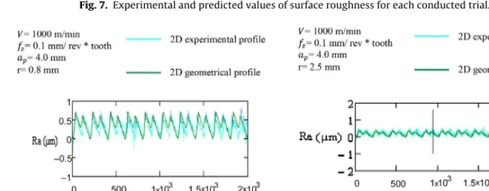
FromTable5itcanbeobservedthatthe%RE*(relativeerror percentageaverage)is2.4.Thisresultisconsideredasanexcellent approach,sincethedevelopedmodelisabletopredictthesurface roughnesswithalmost98%ofaccuracywhencomparingitwith theexperimentalvaluesofsurfaceroughnessobtainedwhenface millingtheAl7075-T7351.Despitethefactthatfew%REgavevalues higherthan2.4%(10%),itmustbehighlightedthatingenerala differenceof20%betweenthethreevaluesofsurfaceroughness measurementsconductedineachmachinedsurfacewasobtained, forthisreasontheapproachofthedevelopedmodelisconsideredas excellent.AvisualrepresentationoftheresultsshowninTable5is presentedinFig.7whereasitwasexpected,anoverlapbetweenthe predictedandexperimentalvaluesofsurfaceroughnessisobserved duetothesmallvalueof%REthatwasachievedbythedeveloped model.
Aspreviously stated the developed model is capable of not onlypredictingthesurfaceroughnessbuttoreproducethe sur-faceroughnessprofile.Fig.8showsacomparisonbetweena2D geometricalprofileobtainedbyusingthedeveloped modeland the2Dexperimentalsurfaceroughnessprofileforspecificcutting conditions.
[image:6.646.301.550.81.395.2] [image:6.646.35.284.83.435.2] [image:6.646.74.244.610.718.2]Fig.7.Experimentalandpredictedvaluesofsurfaceroughnessforeachconductedtrial.
Fig.8. Comparisonbetweenthe2Dprofilesobtainedbythedevelopedgeometricalmodelandtheexperimentalprofile.(a)Trial7and(b)trial16.
highlightedthatthisbehaviorremainedconstantforallthe36 tri-alsthatwereconductedinthisstudy.Finallytheresultsshowthat auniquecuttertoothcandefinethesurfaceprofileofmilledparts whenconsideringthefrontcuttingprocessandtheseresultsarein agreementwiththeresearchofFranco[10].
4. Conclusions
Inthisresearchithasbeendemonstratedtheusefulof devel-oping models for theprediction of thesurface roughness as a fundamentalvariableinthesurfaceintegrityofmechanical com-ponents.Theuseofthemodelsallowsdecreasingtrialanderrors experimentsandthesearchofoptimalvariablesforspecificvalue ofroughness.Thedevelopedmodelissimpletouse,itsaccuracyis 98%,andnotonlyallowsobtainingthevalueofroughnessbutalso thedevelopmentofthe2Dsurfaceroughnessprofile.Themodel canbeappliedtoanycombinationofmaterialworkpieceandtool whentoolwearisnotconsidered.Alsosincethemodelisbasedona geometricalanalysisitcanbeappliedtoanytooldiameter,number ofteethandsquareinsertwithanyvalueoftoolnoseradius.
5. Furtherwork
Consideringtheimportanceandimpactofthetoolwearonthe surfaceroughness,furtherworkwillbeconductedinorderto incor-poratethisvalueonthedevelopmentofanewmodelforsurface roughnessprediction,wheretoolwearmechanismsuchasabrasion andadhesionwillbeconsidered.
Acknowledgements
Theauthorsgratefullyacknowledgepartialsupportofthiswork totheUniversityofBathwiththephysicalfacilitiesneededto com-pleteit.
References
[1]KimJ-D,KangY-H.Highspeedmachiningofaluminiumusingdiamondend mills.IntJMachToolManuf1997;37(8):1155–65.
[2]MedicusK,Daves M,DuttererB, EvansC, Fielder R.Toolwear and sur-facefinishinhighspeedmillingofaluminiumbronze.MachSciTechnol 2001;5(2):255–68.
[3]GadelmawlaES,KouraM,MaksoudTMA,ElewaIM,SolimanHH.Roughness parameters.JMaterProcessTechnol2002;123:133–45.
[4]SaïK,BouzidW.Roughnessmodelinginupfacemilling.IntJAdvManufTechnol 2005;26:324–9.
[5]CakirMC,CihatE,DemirayakI.Mathematicalmodelingofsurfaceroughness forevaluatingtheeffectsofcuttingparametersandcoatingmaterial.JMater ProcessTechnol2009;209:102–9.
[6]ChildsT,MaekawaK,ObitawaT,YamaneY.Metalmachining.Theoryand applications.1sted.UK:JohnWileyandSons;2000.
[7]KalpakjianS.Manufacturingprocessesforengineeringmaterialsand technol-ogy,vol.157–158;2003.p.543–52.
[8]BaekD,KyunT,KimH.Optimizationoffeedrateinafacemillingoperation usingasurfaceroughnessmodel.IntJMachToolsManuf2001;41:451–62. [9]WangY,ChangH.Experimentalstudyofsurfaceroughnessinslotendmilling
Al2014-T6.IntJMachToolsManuf2004;44:51–7.
[10]FrancoP,EstremsM,FauraF.Influenceofradialandaxialrunoutsofsurface roughnessinfacemillingwithroundinsertscuttingtools.IntJMachTools Manuf2004;44:1555–65.
[11]OktemaH,ErzurumluT,KurtaranH.Applicationofresponsesurface method-ologyintheoptimizationofcuttingconditionsforsurfaceroughness.JMater ProcessTechnol2005;170:11–6.
[12]ReddyS,VenkateswaraR.Selectionofoptimumtoolgeometryandcutting conditionsusingasurfaceroughnesspredictionmodelforendmilling.IntJ AdvManufTechnol2006;26:1202–10.
[13]RyuaS,ChoibD,ChongN.Roughnessandtexturegenerationonendmilled surfaces.IntJMachToolsManuf2006;46:404–12.
[14]OzcelikB,BayramogluM.Thestatisticalmodelingofsurfaceroughnessin high-speedflatendmilling.IntJMachToolManuf2006;46:1395–402.
[15]JesuthanamC,KumananS,AsojanP.Surfaceroughnesspredictionhybrid neu-ralnetwork.MachSciTechnol2007;111:271–86.
[16]Zhang J, Chenb J, Kirby D. Surface roughness optimization in an end millingoperationusingtheTaguchidesignmethod.JMaterProcessTechnol 2007;184:233–9.
[image:7.646.136.471.54.206.2] [image:7.646.128.474.232.367.2][18]Arrazola PJ,Özel T,Umbrello D, Davies M, Jawahir IS.Recent advances in modelling of metal machining processes. CIRP Ann Manuf Technol 2013;62:695–718.
[19]Diniz A,FilhoJ.Influence ofthe relativepositionoftool andworkpiece ontoollife,toolwearandsurfacefinishinthefacemillingprocess.Wear 1999;232:67–75.
[20]LinTS.Reliabilityandfailureoffacemillingtoolswhencuttingstainlesssteels. JMaterProcessTechnol1998;79:41–6.
[21]LinTS.ExperimentaldesignandperformanceanalysisofTiN-coatedcarbide toolinfacemillingstainlesssteel.JMaterProcessTechnol2002;127:1–7.
[22]GhaniJA,ChoudhuryIA,HassanH.ApplicationofTaguchimethodinthe opti-mizationofendmillingparameter.JMaterProcessTechnol2004;145:84–92. [23]MontgomeryD.Design,analysesofexperiments.3rded.USA:JohnWileyand
Sons;1997.