A Review of
Flow
Forming Processes and Mechanisms
MARINI Daniele
1, a *,
CUNNINGHAM David
2, band CORNEY Jonathan
3, cDepartment of Design, Manufacture & Engineering Management (DMEM), University of Strathclyde, Montrose Street, Glasgow, UK
adaniele.marini@strath.ac.uk, b Jonathan.Corney@strath.ac.uk, cdave.cunningham@strath.ac.uk
Keywords: Flow Forming, Review, Spinning, Process Modeling, Design of Experiments.
Abstract. After years of purely academic interest and niche applications, today the flow forming process is increasing demand in aerospace, automotive and defense industries. This review surveys academic paper of last fifty years, in order to evaluate the current state-of-the-art for academic and practitioner. Theoretical and experimental approaches are collected and compared by evaluating their prediction models. As a result, several knowledge gaps are identified, for example stress and strain tensors evolutions are not determined for workpiece, due to high computational cost and uncertainty about the correct finite elements approach to adopt. Similarly although, the final microstructure is often evaluated for specific cases, study of its evolution during plastic deformation has not been reported. Residual stress and final material proprieties, such as corrosion behavior, have been not studied numerically or experimentally. Tool path impact and alternative geometries are not deeply explored. Particular attention is given to process experimental optimization and characterization through Design of Experiment, which is still limited to a few papers and sometimes not well developed. The results of this review will help define a research agenda for future developments.
1. Introduction
The flow forming process is becoming more used in forming industry. After its initial introduction in 50s-60s and its use as an alternative of deep drawing, this process felt into obscurely for long time regarding its industrial application. However during this period, research about its mechanics and characterization continued in universities, mainly in Germany and Japan. Essentially flow forming is deformation process acted by rollers that compresses and stretches a blank (called a preform) over a rotating mandrel, usually through consecutive stages. The appearance of heavy duty CNC machines has provided the versatility to fulfill the small-medium batches’ request and with flexibility, which allows a range of designs in addiction to providing final near to net shape. The process allows a reduction in weight and costs, important to industrial applications. Process potentialities are detected in quality enhancing, formable shapes increasing and workable materials range enlarging. Spinning and flow forming techniques have been applied for components production in automotive, aerospace and oil & gas industries. Thus a reduction of cost can be achieved as well as potential lightweight production and near net shape components, eliminating forging steps and further machining. Complete systematic and structured literature review for flow forming, is possible only with a full understanding of the whole processes mechanism. This paper is a first attempt to collect practical and theoretical knowledge in a systematic way. For this reason, the methodology described in [1] for shear forming is applied, in order to acquire the required knowledge and investigation aims for flow forming. The other few reviews in literature such as [2]
and [3] do not have a systematic approach. In order to apply [1] methodology to flow forming,
2. Investigative methodologies
Experimental Methodologies are used for investigating a huge range of process and product characteristics. Mainly applied strategies consist in the correlation between material and the input process parameters with measured output or in-process evaluation of characterizing entities. The measured characteristics in the flow forming experiments are typically the radial, tangential and axial forces measured on the rollers measurement, during the operation; direct evaluation of surface roughness and indirect evaluation of material properties through microscopic and optical investigations; evaluation on material and mechanical proprieties of the final piece through destructive test or on-process parameters measurement; dimensional accuracy evaluation of the worked product. In [4], backward and forward variants have been investigate with different reduction ratios and parameters setting on mild steel. They evaluate the impact of process variables on a product’s dimensional accuracy and schematize the different material flow conditions in the different setting through the definition of plastic wave of material. A coefficient that defines the size of the wave is introduced in order to evaluate the instability of the process. As observed in [5], correct tool geometry (attack angle) impacts enormously on axial flow and circumferential, in order to avoid huge friction phenomena. [6] test precedent theories on hardest and low deformable materials. [7] investigate the forming limit in Aluminum alloys for forward and backward flow forming, adopting different process parameters and rollers configurations. Micro-spinnability and macro-spinnability are evaluated for the four combinations of materials and heat treatments. The latter is evaluated through thickness reduction until failure (destructive technique) or until reaching the desired reduction ratio (non-destructive). [6] explore the effect of flow forming on steel using Vickers and Rockwell hardness evaluation. They also map the relationship between axial contact and circumferential contact, which are evaluated using the axial on circumferential contact methodology developed by [8]. The microstructure is investigated in order to detect the grade of grain elongation, in comparison with thickness reduction. The authors described the phase of production through a flowchart and they use analytical methods for determining the preform dimensions and the expected ultimate strength. [9] investigate the insurgence of defects in flow forming steel tubes production. [10] perform different test on flow formed pressure vessels in AISI 4130 steel in order to evaluate the effect of the heat treatments. [11] investigate the cracks propagation mechanism for Niobium alloys. [12] deploy causes of roundness errors and other quality unconformities in flow forming processes. [13] test surface micro hardness of workpiece for mapping equivalent true stress strain along forward flow forming operation. Evolution of strain is characterized by roller/mandrel contact and thickness reduction ratio. [14] relate the indentation hardness and the Von-Mises true strain for flow forming of splined steel wheels. The authors map strain in dependence on mandrel’s external surface detachment, for different type of reduction ratio. Same approach used later in [15] for evaluating hardening in internal splined wheels forming. [16]
discuss the influence of heat treatment of the preform above reduction ratio and steel final strength for backward flow forming. [17] investigate the influence of process parameters on fatigue behavior of flow formed wheels for automotive industry.
authors propose and optimize a set of variables, which are built by simulation trials of validation.
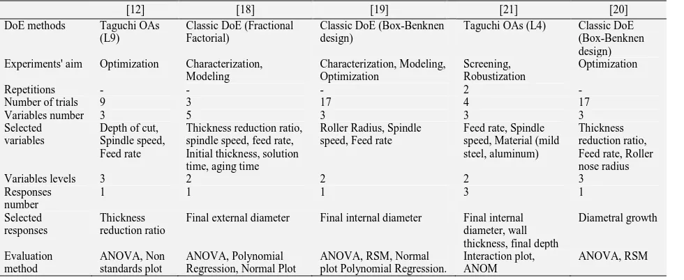
[image:3.595.59.549.139.340.2][21] use only an interaction plot and analysis of means without producing optimization of output.
Table 1 summarizes DoE approaches.
Table 1: Summary of experimental DoE approaches to flow forming.
[12] [18] [19] [21] [20]
DoE methods Taguchi OAs (L9)
Classic DoE (Fractional Factorial)
Classic DoE (Box-Benknen design)
Taguchi OAs (L4) Classic DoE (Box-Benknen design) Experiments' aim Optimization Characterization,
Modeling Characterization, Modeling, Optimization Screening, Robustization Optimization
Repetitions - - - 2 -
Number of trials 9 3 17 4 17
Variables number 3 5 3 3 3
Selected variables
Depth of cut, Spindle speed, Feed rate
Thickness reduction ratio, spindle speed, feed rate, Initial thickness, solution time, aging time
Roller Radius, Spindle speed, Feed rate
Feed rate, Spindle speed, Material (mild steel, aluminum)
Thickness reduction ratio, Feed rate, Roller nose radius
Variables levels 3 2 2 2 3
Responses number
1 1 1 3 1
Selected responses
Thickness reduction ratio
Final external diameter Final internal diameter Final internal diameter, wall thickness, final depth
Diametral growth Evaluation method ANOVA, Non standards plot ANOVA, Polynomial Regression, Normal Plot
ANOVA, RSM, Normal plot Polynomial Regression.
Interaction plot, ANOM
ANOVA, RSM
Theoretical Methodologies (Analytical and Numerical). Theoretical methodologies are able to investigate the tension and displacement states and their evolution in the deformed blank during the whole process. A combination of this knowledge with failure or deformation models and criteria can predict the failure, damage accumulation and final characteristics of the worked piece.
Analytical methodologies aim to develop a theoretical model in order to forecast the flow of the metal during the process. This would provide an evaluation of the working energies and forces required for a given designed geometry. This can also give general feasibility boundaries to the process (e.g. maximum reduction ratio).Each model starts with the hypothesis of volume constancy, and they evaluates the proportionality between axial growth and radial reduction. [22] use a grid-lines model in order to evaluate the tri-axial state of strain during flow forming process. [23]
develop an energy model in order to predict the working forces and their relation with the reduction ratio. They divide the energy exchange in the process into four main parts: plastic deformation energy (under the roller), velocity discontinuity energy consumption (due to the metal flow velocity discontinuities in the various worked zone), frictional energy (contacts mandrel/piece and piece/rollers), blocking energy (mandrel constrains). [24] simplify the approach described in [23]
approach for stainless steels, excluding diametral growth, which is negligible for hard materials. They evaluate power absorbance by friction and velocity, and conclude that the first parameter has no influence. [25] use the same model but with different reference system. Regarding aluminum alloys, another application of [23] model is perform by [26], including diametral growth and plasticity parameters. [7] use upper-bound method for analyzing the contact between roller and workpiece during flow forming process. This allows the authors to develop simple a formulas for S
(circumferential contact) and L (axial contact). In this way, it is possible to evaluate S/L ratio for establishing dominant flow between axial and circumferential deformation. This methodology has been tested and confirmed valid for different conditions and materials by several papers, through numerical and experimental method [9,12,20, 23,27,28]. [27] extend this work in order to obtain a detailed analytical expression of contact zone. [29] develop an upper-bound method built in comparison with tubes ironing. [30] adopt previous models for shear forming and spinning in order to evaluate their approaches. [31] develop a simple formula for the calculation of the tension through monitoring continuously the forces with power sensors.
through a previous evaluation of the final geometry of the workpiece. The implicit necessity of 3-dimensional modeling and complexity of contact surfaces create difficulties in this kind of approach. A total of eleven papers have developed numerical models for flow forming. Three papers use an implicit approach [4,30,32], meanwhile six use an explicit approach [26,27,33–36]. Implicit code is more related to nature of the problem than explicit one. Although because non-linearity of the process creates difficulty in an implicit solution’s convergence and high computational cost which causes more researcher to use explicit approaches. Explicit approach seems to be best alternative because of its robustness and computational efficiency, even if produce mainly a quasi-static response. Explicit code is also conditionally stable and time step incur to obvious limitations. Elevate number of increments is necessary, due to large natural process time.
3. Mechanics of flow forming
Prediction of product final geometry. Definition of final product geometry is main task of research in flow forming. Several authors develop knowledge, experimentally and theoretically, about changes in final expected workpiece dimension. In flow forming, final diameter is imposed by roller distance although several effects, such as springback, material proprieties and tension state influence final shape of formed product. Accuracy of product diameter and dimensional tolerance are related between process parameters and configuration. Diametral growth affects mainly soft material (aluminum or copper alloys) as described theoretically by [23] and [24]. The diametral growth increases with decreasing in feed rate and increasing in depth of cut [39]. Circumferential on axial length on contacts ratio (S/L) is primary technique for minimizing this factor [9]. There is no theoretical model available to accurately predict springback. It generally depends on the amount of reduction, strain hardening exponent of the material, geometry of the roller and feed [9]. Roundness
error is influenced by depth of cut and feed rate. Depth increasing decreases workpiece roundness, due to most uniform deformation under the roller. On the other hand, this deformation causes other defects (e.g. waviness). In this field, improved FEM models, including material characterization, and experimental models would have great impact on geometrical prediction. Better connection needs to be established between analytical models, FEM and experimental validation. For now, S/L remains a good measurement of process parameters impact on flow forming process accuracy.
Prediction of surface properties. Relationship between process parameters and surface roughness is an open field in flow forming research. In [6], surface finishing seems to be independent from reduction ratio and always less than 0.9 µm (Ra) for stainless steel and hard to deform alloy, such as Titanium or Inconel. Lubricant selection has impact on surface finishing of these materials. For steel, surface obtained is between 0.5 and 0.8 µm. The impact of different lubricants and reduction ratios influences these values but surface roughness never falls below or exceed the cited values
[40]. An increase in feed rate impacts negatively on surface roughness, due to the consequent radial force’s increase. With a constant roller radius value, [9] notice an increasing of roughness with a feed ratio increasing. Same authors develop the only empirical relationship for calculating marks’ height on the surface. Material microstructure, feed rate and roller dimensions are parameters with most impact on surface roughness. Surface roughness prediction is still an open field for research. A higher number of experimental researches should investigate influence of other characteristic of preform on final surfaces roughness. In a future, FEM models would be able to use material grains as element and consequently predict surface roughness.
Prediction of mechanical proprieties. Due to cold process nature, material mechanical proprieties or workpiece change during flow forming operation. Relationship between them and process parameters are not only subject of study in this field. Initial microstructure and heat treatments have huge impact on product properties as well as anisotropy of final microstructure. Hollomon's power law is deployed by some authors [20,23] for predicting the final ultimate strength of a component, which appears to be a good approximation. Erasmus law, used in [10], is derived from Hollomon’s
fatigue strength of flow formed components. Fatigue testing evidences a non-complete relationship with surface roughness. A strict correlation is founded between fatigue strength and microcracks on the surface generated by flow forming process. Defining correctly product final proprieties ensures proper process and further operations’ design, for reaching product quality targets.
Prediction of product microstructure and its effects: Material behavior plays a fundamental role in severe cold plastic forming process, so preform microstructure and heat treatments. Evolution of microstructure for different process configuration is tested by several authors. The anisotropy of the final flow formed structure is tested in [41]. The grains are stretched along the flow forming axis. As, consequence, the catastrophic crack in burst test happens in hoop direction instead axial. As exposed in [14] for steel, elongation of the worked material grains along the feed axes is noticed as well as ferrite grains stretch in the zone of huge plastic deformation. These zones are usually located in the mandrel contact zone. Generally, increasing carbon content and increasing amount of alloying elements decrease spinnability as well as inclusion and precipitates. Generally, low carbon alloys should not be used [10]. For hard to deform material, [6] notice no valuable changes in the micro-hardness, for dissimilar reductions ratio. In [11], a niobium alloy has huge hardening in first pass, which compromises the structure integrity in sequent forming steps. So annealing is preferable between the passes. [7] suggests that the aluminum alloys may reach a spinnability of 0.7 (limited only for solution-treated alloys). The micro-hardness investigation shows a clear inhomogeneity related to the anisotropy of the final structure, due to elongated grains in axial direction, increasing exponentially with increases in thickness reduction. Surface hardness demonstrate same relationship with thickness reduction [6,11,26]. Different heat treatments (quenching, tempering, annealing) are evaluated in [5] as influent parameter on final microstructure of the flow formed parts. Annealing does not give resilience to crack propagation, less strength and hardness. Adversely, tempering and quenching give the opposite effect but impurities and inclusions limit their usage. They propose an ideal combined heat treatment cycle, based on ideal combination of strength and toughness. [10]
agree with the previous statement, including normalizing in the tested heat treatments for steels. The annealing improves steel formability and decreases working stresses and forces but do not provide enough tensile strength to final part, differently from other hardening treatments.
Prediction of stresses and strains evolution is consequent step of forces prediction. Therefore, damage evolution is assessed to workpiece along forming operation. None of the authors complains about residual stress insurgence and their impact on stress/strain behavior and proprieties of worked product. Material microstructure evolution is not studied in comparison with strain behavior during process. [13] deduct maximum equivalent plastic strain form experimental measures of surface hardness. A map of true strain is developed for all contact regions. Setting a maximum admissible strain is possible to map available thickness reductions. [15] use similar procedure for mapping equivalent strain of two aluminum alloys. Alloy with greatest point-to-point difference in equivalent Authors associate strain behavior to high alloy grains variation, and yield stress increasing to hardening behavior. Front tension increases with deformation ratio but decreases with frictional forces’ increase between workpiece and mandrel, as in [31] though sensor measurement during flow forming of tubes. [32] identify complex tensional and strain states in contact zone, dividing it in three zones. Numerical model results are in agreement with [23].
Table 2: Effect of process parameters on forming forces components and forming power.
Process parameters Force components Total forming
Power
Axial Tangential Radial
Increasing feed ratio + + + +
Increasing mandrel speed negligible negligible negligible negligible Increasing working depth not available not available not available not available
Increasing thickness reduction ratio + + + +
Increasing preform diameter + negligible + +
Increasing roller attack angle + + - optimum exists
Increasing roller nose radius not available not available not available not available
increasing roller diameter + negligible + +
increasing friction factor + + not clear optimum exists
Increasing preform hardness + not clear not clear not clear
Increasing preform yield strength + + + +
Increasing preform ductility not clear not clear not clear not clear
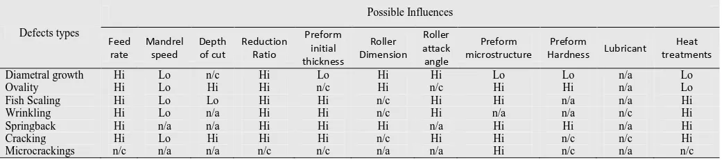
Prediction of failure. Prediction of instant stresses, accumulated strains and damage evolution should lead to an understanding of failure mechanisms and the prediction of failure [1]. Due to absence of general connection with strain and stresses, modes of failure have been identified in fracture and their defects insurgence. Different authors identify fracture phenomenon as result of tension in forward flow forming and buckling in backward. [7] individuate the critical reduction ratios for microcracks propagation. Reaching them, fractures become visible at the microscope. Main reason for generating of this phenomenon is nucleation of microvoids, due to inclusions and incoherent particles. This propagation is registered both on surface and on the material matrix. Also if material appears to have good macro-spinnability proprieties, microcracks eventually extend to form cracks both in axial and circumferential direction. These defects generated on the surface will degrade the surface finish and eventually reduce the feasible thickness reduction, also if part looks good at naked eyes. Although these deformations have only small effects on the ultimate tensile strength, they affect fatigue life and extended in macrocracks for higher reduction ratio. Microcracks and macrocracks are strictly connected with flow stability [10]. Excessive diametral growth (thickness variation), ovality (out-of-roundness), fish scaling (bulging or waviness), wrinkling and springback are main defects, which may occur during flow forming process. Table 3
summarizes defects types and effects of process issues on their insurgence. Ovality is influenced by feed rate and roller radius, but the defect can be minimized through correct selection of these two parameters, as deployed in [42]. Decreasing feed rate produces deformation in radial direction, which causes an increasing in ovality. Highest values of feed rate combined with low reduction rate produce largest ovality. [16] assert influence of heat treatments and microstructure on ovality.
the relationship between defects and the ratio of circumferential on axial contact length is used by several authors. S/Lratio expresses plastic flow quality for given of process parameters; therefore it represents a simple and effective instrument for obtaining indications about defects insurgence. If axial contact length (L) overcomes circumferential length (S), circumferential plastic flow dominates (S/L<1). Geometrical inaccuracies and defects emerge in this case. Increasing S/L,
[image:7.595.39.561.262.378.2]interfacial friction enhances axial flow. In this case (S/L>1), most of material flows in axial direction and defects tend to disappear. Although, if contact ratio becomes too large (S/L>>1), friction coefficient become close to unity and material flow at angle smaller than attack angle. In this case, wave-like surfaces and thickness variation in workpiece occur. Initial thickness, feed rate, roller attack angle and reduction ratio need to be balanced in order to obtain a defect less part. Material failure is connected with tension and stress tensors, crack propagation mechanism and process instability.
Table 3: Influences of process parameters on defects and geometrical inaccuracies (H, high; L, low; n/a, not available; n/c not clear)
Defects types
Possible Influences
Feed rate
Mandrel speed
Depth of cut
Reduction Ratio
Preform initial thickness
Roller Dimension
Roller attack angle
Preform microstructure
Preform
Hardness Lubricant
Heat treatments
Diametral growth Hi Lo n/c Hi Lo Hi Hi Lo Lo n/a Lo
Ovality Hi Lo Hi Hi n/c Hi n/c Hi Hi n/a Lo
Fish Scaling Hi Lo Lo Hi Hi n/c Hi Hi n/a n/a Hi
Wrinkling Hi Lo n/a Hi Hi n/c Hi n/a n/a n/c Hi
Springback Hi n/a n/a Hi Hi Hi n/a Hi Hi n/a Hi
Cracking Hi Lo Hi Hi Hi n/c Hi Hi n/c n/c Hi
Microcrackings n/c n/a n/a n/c n/c n/a n/a Hi n/c n/a n/c
4. Conclusions
The sensitivity of the flow forming process to material properties affects both prediction accuracy and so the impact of theoretical models. This study has identified several knowledge gaps. Stress and strain tensors evolutions are not fully determined for workpiece, due to high computational cost and difficulty in identify the best finite elements approach. Ratio of circumferential to axial contact is widely used as a defect prediction parameter, although the process’ failure mechanism is still not fully understood. Forming forces and powers are fully analytically and numerically defined in correlation with process parameters. None of the review authors connects microstructural evolution with instant stresses and accumulated strains in order to obtain a general model of failure. Final microstructure is often evaluated for specific cases but its evolution during plastic deformation is not studied. Residual stress, springback and some final material proprieties, such as corrosion behavior, have been not studied numerically or experimentally. Tool path impact and alternative geometries are not deeply explored. Similarly, microcracks investigation and causes are not well investigated. Process experimental optimization and characterization through Design of Experiment is still limited to a few papers and usually not well developed. Lack of accurate numerical models makes it difficult to do process optimization through algorithms. Consequently an empirical approach needs to be adopted so heat treatment experiments and flow forming operation need to be systematically performed in order to achieve required properties for final component. In this regard the DoE approach has unrealized potential for optimization of geometrical inaccuracy and final properties in many flow forming processes.
References
[1] O. Music et al., A review of the mechanics of metal spinning, J.Mat.Pro.Tech. (JMPT) 210 (2010) 3-23. [2] M. Sivanandini et al., Flow Forming Of Tubes-A Review, Int. J. 5 (2012) 1-11.
[3] C. Wong et al., A review of spinning, shear forming and flow forming processes, IJT&M 43 (2003) 1419-1435. [4] M. Hayama, H. Kudo, Experimental Study of Tube Spinning, JSME,167 (1979) 769-775.
[6] R.P. Singhal et al., Some Experimental Observations in the Shera Spinning of Long Tubes,JMWT,14(1987)149-157. [7] S.C. Chang et al. Tube spinnability of AA 2024 and 7075 aluminum alloys, J.Mat.Pro.Tech, 80-81 (1998) 676-682. [8] M. Gur, J. Tirosh, Plastic flow instability under compressive loading during shear spinning process, ASME, 1(1982) 17–22.
[9] K. M. Rajan et al., An Investigation of the Development of Defects During Flow Forming of High Strength Thin Wall Steel Tubes, Prac.Fail.An. 1 (2001) 69-76.
[10] K.M. Rajan, P. U. Deshpande, K. Narasimhan, Effect of heat treatement of preform on the mechanical proprieties of flow formed AISI 4130-a theoretical an experimental assessment, J.Man.Pro.Tech. 126 (2002).
[11] R.K. Gupta et al., Investigation of Cracks Generated During Flow Forming of Nb-Hf-Ti Alloy Sheet, J.Fail. An, 6 (2007) 424-428.
[12] M.J. Davidson, K. Balasubramanian, G.R.N. Tagore, Experimental investigation on flow-forming of AA6061 alloy-A Taguchi approach, JMPT 200 (2008) 283-287.
[13] M.J. Roy et al., Evolution of plastic strain during a flow forming process, JMPT, 209 (2009) 1018-1025.
[14] M. Haghshenas et al., Plastic strain distribution during splined-mandrel flow forming, M&D, 32 (2011) 3629-3636. [15] M. Haghshenas et al., Investigation of strain-hardening rate on splined mandrel flow forming of 5052 and 6061 aluminum alloys, Mat.Sc. 532 (2012) 287-294.
[16] B. Podder et al., Effect of preform heat treatment on the flow formability and mechanical properties of AISI4340 steel, M&D 37 (2012)174-181.
[17] S. Notarigiacomo et al., The influence of flow-forming process parameters on the fatigue behaviour of high-strength steel wheels for the automotive industry, EC Off. Publ. (2009).
[18] A.R.F. Nahrekhalaji et al., Modeling and Investigation of the Wall Thickness Changes and Process Time in Thermo-Mechanical Tube Spinning Process Using Design of Experiments, Eng., 2 (2010) 141-148.
[19] M. Srinivasulu et al., Experimental investigations to predict mean diameter of AA6082 tube in flow forming process- DOE approach, IOSRJEN 2 (2012) 52-60.
[20] A. Jalali Aghchai et al., Flow forming optimization based on diametral growth using finite element method and response surface methodology, J. Eng. Man. 226, (2012) 2002-2012.
[21] L. Wang et al., Roller path design by tool compensation in multi-pass conventional spinning, M&D 46(2013)645-653.
[22] T.R. Mohan et al., Studies on power spinning of tubes, Int. J.Prod.Res., 10 (1970) 351-364.
[23] M. Hayama at al., Analysis of Diametral Growth and Working Forces in Tube Spinning, JSME 22 (1979) 776-784. [24] R.P. Singhal, N. Delhi, P.K. Saxena, N.G. Commission, R. Prakash, Estimation of Power in the Shear Spinning of Long Tubes in Hard-To-Work Materials, J. Mat. 23 (1990) 29-40.
[25] S.S. Jolly et al., Analysis of Power and Forces in the Making of Long Tubes in Hard-to-Work Materials, Proc.W.Congr.Eng. 2 (2010).
[26] H.R. Molladavoudi, F. Djavanroodi, Experimental study of thickness reduction effects on mechanical properties and spinning accuracy of aluminum 7075-O, Int.J.Adv.Man.Tech. 52 (2010) 949-957.
[27] M.J. Roy et al., Analytical solution of the tooling/workpiece contact interface shape during a flow forming operation, JMPT 210 (2010) 1976-1985.
[28] M.H. Parsa, et al., Flow-forming and flow formability simulation, Int. J. Adv. Man. Tech. 42 (2008) 463-473. [29] J.W. Park, Y.H. Kim, W.B. Bae, Analysis of tube-spinning processes by the upper-bound stream-function method, JMPT 66 (1997) 195-203.
[30] H.N. Nagarajan et al., Mechanics of Flow Forming, CIRP Ann – Man. Tech. 30 (1981)159-162. [31] K.S. Lee, L. Lu, A study on the flow forming of cylindrical tubes, JMPT 113 (2001) 739-742.
[32] Y. Xu, S. Zhang, P. Li, K. Yang, D. Shan, Y. Lu, 3D rigid–plastic FEM numerical simulation on tube spinning, JMPT 113 (2001) 710-713.
[33] X. Kemin et al., Elasto-plastic FEM analysis and experimental study of diametral growth in tube spinning, JMPT 69 (1997) 172-175.
[34] X. Kemin et al., The disposal of key problems in the FEM analysis of tube stagger spinning, JMPT 69(1997)176-179.
[35] C.C. Wong et al., Effects of roller path and geometry on the flow forming of solid cylindrical components, JMPT 167 (2005) 344-353.
[36] H. Lexian et al., An analytical contact model for finite element analysis of tube spinning process, JEM 222 (2008) 1375-1385.
[37] K. Li et al., Research on the distribution of the displacement in backward tube spinning, JMPT 79 (1998) 185-188. [38] M.S. Mohebbi at al., Experimental study and FEM analysis of redundant strains in flow forming of tubes, JMPT 210 (2010) 389-395.
[39] M. Joseph Davidson et al., An experimental study on the quality of flow-formed AA6061 tubes, JMPT, 203 (2008) 321-325.
[40] R. Prakash et al., Shear spinning technology for manufacture of long thin wall tubes of small bore, JMPT 54 (1995) 186-192.
[41] K.M. Rajan et al., Experimental studies on bursting pressure of thin-walled flow formed pressure vessels, JMPT 125-126 (2002) 228-234.