Rochester Institute of Technology
RIT Scholar Works
Theses Thesis/Dissertation Collections
2010
Evaluating the effectiveness of packet filter firewall
applications in a “dual stack” internet protocol
environment
Walter C. Snyder
Follow this and additional works at:http://scholarworks.rit.edu/theses
This Thesis is brought to you for free and open access by the Thesis/Dissertation Collections at RIT Scholar Works. It has been accepted for inclusion in Theses by an authorized administrator of RIT Scholar Works. For more information, please [email protected].
Recommended Citation
Evaluating the effectiveness of packet filter firewall applications in a “dual stack”
Internet Protocol environment
by
Walter C. Snyder II
Thesis submitted in partial fulfillment of the requirements
for the degree of
Master of Science in
Computer Networking and System Administration
Rochester Institute of Technology
B. Thomas Golisano College of Computing and Information Sciences
Department of Networking, Security & Systems Administration
Thesis Approval Form
Rochester Institute of Technology
B. Thomas Golisano College of Computing and Information Sciences Department of Networking, Security & Systems Administration
Master of Science in
Computer Networking and System Administration for
Evaluating the effectiveness of packet filter firewall applications in a “dual stack” Internet Protocol environment
by
Walter C. Snyder II
Thesis Committee
Name Signature Date
Dr. Sumita Mishra, Assistant Professor, Ph.D.
Chairperson
Daryl G. Johnson, Associate Professor
Committee Member
Dr. Charles Border, Associate Director, Ph.D.
ii
Thesis Reproduction Permission Form
Rochester Institute of Technology
B. Thomas Golisano College of Computing and Information Sciences Department of Networking, Security & Systems Administration
Evaluating the effectiveness of packet filter firewall applications in a “dual stack” Internet Protocol environment
by
Walter C. Snyder II
Reproduction Permission
I, Walter C. Snyder II, hereby grant permission to the Wallace Library of the Rochester Institute of Technology to reproduce my thesis in whole or part. Any reproduction must not be for commercial use or for profit.
iii
iv
Abstract
It is becoming more apparent that there is a need for service providers to update their deployment plans for Internet Protocol version 6 or IPv6. The availability of IPv4 addresses is expected to reach exhaustion in late 2011 [1]. Transition to IPv6 will not happen all at once. Devices using IPv6 networking, are being introduced to an environment entrenched with Internet Protocol version 4 or IPv4. For network service and infrastructure providers, this means a period of time where support for both Internet protocols will be necessary. The “dual IPv4, IPv6 stack” is a reality to be dealt with for the next several years.
IPv6 solves the IP address capacity problem and brings new features but it also brings new risks. The “dual stack” approach increases the number of potential contact points between networked devices and will require an increase to the scope of interface management. For the network administrator, it will be important to understand how the “dual stack” environment will function and how to assure security.
Technology providers have been implementing IPv6 capabilities including networking services and security tools for the past several years in anticipation for the transition from IPv4 to IPv6. This thesis will describe the technical background and an experiment to test the
v
Acknowledgements
vi
Table of Contents
1 Introduction ... 1
1.1 Thesis statement ... 1
1.2 Understanding the need for firewall research ... 2
1.2.1 Firewall fundamentals ... 3
1.3 IPv6 overview ... 4
1.3.1 IPv6 RFCs ... 4
1.3.2 Where IPv6 fits into the network “stack” ... 6
1.3.3 IPv6 packet architecture compared to IPv4 ... 8
1.3.4 IP address representation and assignment ... 11
1.3.5 Next header or protocol codes ... 14
1.4 Security concerns for IPv6 ... 16
1.5 Implications of research ... 16
1.6 Hypothesis: ... 17
1.7 Summary ... 17
2 Related work ... 18
2.1 “Evaluation and testing of Internet firewalls,” 1999 ... 18
2.2 “IPv6 Firewall with OpenBSD,” 2002 ... 18
2.3 “IPv6 Packet Filtering,” 2005 ... 19
2.4 “Packet Filter Algorithm to prevent the security hole of routing header in IPv6,” 2006 20 2.5 “Security aspects in IPv6 networks – implementation and testing,” 2007 ... 20
2.6 “Firewall Design Considerations for IPv6,” 2007 ... 20
2.7 “Design and Implementation of Distributed Firewall System for IPv6,” 2009 ... 21
2.8 “Guidelines on Firewalls and Firewall Policy,” 2009 ... 22
2.9 “IPv6 support in firewalls,” 2009 ... 22
2.10 Summary ... 22
3 Approach and Methodology ... 24
3.1 Common Criteria ... 24
vii
3.3 A criteria for evaluating the effectiveness of packet filter firewall applications ... 27
3.4 Summary ... 28
4 Experiment ... 29
4.1 Experimental system and packet filter firewall applications under test ... 29
4.1.1 system-config-iptables in Fedora Core 10 ... 30
4.1.2 Windows Firewall with Advanced Security in Windows Server 2008 ... 30
4.2 Scope and firewall test application ... 31
4.2.1 Transmission Control Protocol (TCP) ... 31
4.2.2 Modeling the TCP/IP packet filtering process ... 32
4.2.3 Port number assumptions ... 35
4.2.4 Port scanning/connectivity tool - Nmap ... 35
4.3 Experimental Steps ... 37
4.3.1 Install and configure “Server Host” system ... 37
4.3.2 Deploy a packet filter firewall using the “application under test” ... 37
4.3.3 Confirm listening services on “Server Host” ... 38
4.3.4 Connectivity of “Server Host” with firewall “as designed” ... 38
4.3.5 Connectivity of “Server Host” with firewall in “accept all” and “block all” ... 38
5 Results ... 39
5.1 System-config-firewall/iptables on Fedora Core 10/Linux ... 39
5.1.1 “Server Host” and “Observer Host” configuration ... 39
5.1.2 Creating a packet filter firewall using “system-config-firewall” ... 40
5.1.3 Confirming listening services on Fedora Core 10, “Server Host” ... 44
5.1.4 Connectivity of Fedora Core 10 server with firewall “as designed” ... 45
5.1.5 Connectivity of Fedora Core 10 “Server Host” with firewall “accept all” ... 48
5.1.6 Connectivity of Fedora Core 10 server with firewall “block all” ... 50
5.1.7 Summarizing results, “system-config-firewall/iptables” ... 52
5.2 Windows Firewall with Advanced Security ... 55
5.2.1 “Sever Host,” Windows Server 2008 configuration ... 55
5.2.2 Creating a packet filter firewall using Windows Firewall with Advanced Security 55 5.2.3 Confirming listening services on Windows Server 2008 ... 58
5.2.4 Connectivity of Windows Server 2008 with firewall “as designed” ... 59
viii
5.2.6 Connectivity of Windows Server 2008 with firewall “block all” ... 63
5.2.7 Summarizing results with Window Firewall with Advanced Security ... 66
5.3 Results Summary ... 68
6 Conclusion ... 70
6.1 Recommendations ... 70
6.2 Future work ... 70
6.3 Summary ... 71
7 Works Cited ... 73
Appendix A: Usage notes: System-config-firewall/iptables ... 77
A.1. Fedora Core 10 Firewall from the Control Panel ... 79
A.2. A granular view of firewall rules ... 81
A.3. Problem with the initial firewall created by system-config-firewall. ... 82
A.4. Adding a new rule ... 83
A.5. Summary ... 84
Appendix B: Usage Notes: Windows Firewall with Advanced Security ... 85
B.1. Windows Firewall from the Control Panel ... 85
B.2. Window Firewall Settings ... 86
B.3. Windows firewall from a MMC view ... 87
B.4. Monitoring ... 88
B.5. Firewall Properties and Log file settings ... 89
B.6. Access to individual rules ... 90
B.7. Narrowing down the list of rules... 90
B.8. Looking for just TCP protocol related rules ... 91
B.9. Adding a new rule ... 92
B.10. Properties of a specific rule ... 93
ix
List of Figures
Figure 1. Comparison of IPv6 and IPv4 packets ... 8
Figure 2. Types and examples of IPv6 and IPv4 address prefixes ... 12
Figure 3. Experimental system ... 29
Figure 4. TCP’s “three way handshake” process ... 32
Figure 5. An IPv6 packet with a TCP protocol payload ... 33
Figure 6. Modeling firewall operation ... 34
Figure 7. “Trusted Services” window, system-config-firewall ... 40
Figure 8. “Other Ports” window, system-config-firewall ... 41
Figure 9. “ICMP Filter,” system-config firewall ... 41
Figure 10. Output from "service iptables status," Fedora Core ... 43
Figure 11. Output from "service ip6tables status," Fedora Core ... 43
Figure 12. Inventory of listening services, Fedora Core ... 44
Figure 13. Port scan results of IPv4 address, Fedora Core “Server Host” ... 46
Figure 14. Port scan results of IPv6 address, Fedora Core “Server Host”, part a ... 47
Figure 15. Port scan results of IPv6 address, Fedora Core “Sever Host,” part b ... 47
Figure 16. Results of “service iptables stop,” Fedora Core “Server Host” ... 48
Figure 17. Results of “service ip6tables stop,” Fedora Core "Server Host"... 48
Figure 18. Port scan results of IPv4 address, “permit all” fw, Fedora Core "Server Host"... 49
Figure 19. Port scan results of IPv6 addresses, “permit all” fw, Fedora Core "Server Host" ... 50
Figure 20. Results of “service iptables panic” ... 50
Figure 21. Results of “service ip6tables panic” ... 51
Figure 22. Port scan results of IPv4 address, “block all,” Fedora Core “Server Host” ... 51
Figure 23. Port scan results of IPv6 address, “block all,” Fedora Core “Server Host” ... 51
Figure 24. PING port scan results of IPv6 address, “block all,” Fedora Core “Server Host”... 52
Figure 25. Output from “wireshark” while running “nmap –PN”... 52
Figure 26. Inbound rules window, “Windows Firewall with Advanced Security” ... 56
Figure 27. Properties window, “netcat_allow” rule ... 57
Figure 28. Output , “netstat -anp TCP” and “netstat -anp TCPv6” ... 58
Figure 29. Port scan results of IPv4 address, Windows 2008 Server “Server Host”... 60
Figure 30. Port scan results of IPv6 address, Windows 2008 Server “Server Host”... 61
Figure 31. Port scan results of IPv4 address, “permit all” fw, Windows 2008 “Server Host” ... 62
Figure 32. Port scan results of IPv6 address, “permit all” fw, Windows 2008 “Server Host” ... 63
Figure 33. Port scan results of IPv4 address, “block all” fw, Windows 2008 “Server Host” ... 64
Figure 34. Port scan results of IPv6 address, , “block all” fw, Windows 2008 “Server Host” ... 65
Figure 35. Port scan with –PN, of IPv6 address, “block all” fw, Windows 2008 “Server Host” ... 65
x
Figure 37. “Trusted Services” window, system-config-firewall ... 79
Figure 38. “Other Ports” window, system-config-firewall ... 80
Figure 39. ICMP filter window, system-config-firewall ... 80
Figure 40. Results of “service iptables status,” Fedora Core ... 81
Figure 41. Results of “service ip6tables status,” Fedora Core ... 82
Figure 42. Revised iptables ... 83
Figure 43. Revised ip6tables ... 83
Figure 44. Windows Control Panel view of Windows Firewall ... 85
Figure 45. Windows Firewall panel ... 86
Figure 46. “General” and “Exceptions” configuration ... 87
Figure 47. Windows Firewall, MMC view ... 88
Figure 48. Windows Firewall, Monitoring ... 88
Figure 49. Windows Firewall, “Domain” and “Customize” tabs within Properties window ... 89
Figure 50. Customize Logging, Public Profile ... 89
Figure 51. Inbound Rules, Windows Firewall with Advanced Security ... 90
Figure 52. Inbound Rules filtered, Windows Firewall with Advanced Security ... 91
Figure 53. Inbound Rules filtered and sorted, Windows Firewall with Advanced Security ... 91
xi
List of Tables
Table 1. Terminology, Portions adapted from RFC 2460 [2] ... xii
Table 2. Major RFCs relating to IPv6 ... 5
Table 3. OSI Model and related protocols and data structures ... 7
Table 4. Codes: IPv4/Protocol and IPv6/Next Header ... 14
Table 5. Threats listed in the “Firewall Protection Profile” [33] ... 25
Table 6. Categories of Criteria from ICSA “Modular Firewall Certification Criteria” [35] ... 26
Table 7. Snyder’s criteria for evaluating “dual stack” Internet Protocol firewall applications .... 27
Table 8. Well known port numbers used with TCP transport protocol ... 35
Table 9. “nmap” interpretation of response to “syn” request ... 36
Table 10. Summary of results, “system-config-firewall/iptables” ... 53
Table 11. Summary of results, “Windows Firewall with Advanced Security,” ... 67
xii
Table 1. Terminology, Portions adapted from RFC 2460 [2]
Node a device, e.g., a computer that implements either or both Internet protocol
version 4 or version 6
Router a device that forwards IP packets not explicitly addressed to itself
Host any node that is not a router
Upper layer a protocol layer above the IP layer
Link a communication facility or medium over which nodes can communicate at
the link layer or the layer immediately below the IP layer. An example would
be Ethernet.
Neighbors nodes attached to the same link
Interface a node’s attachment to the link
Address an ip layer identifier for an interface
Packet an IP header plus its payload
Link MTU the maximum transmission unit or maximum packet size in bytes or octets
Path MTU the minimum transmission unit of all the links between a source and
destination
Firewall a hardware of software device that sits between the network and a host or
another network that filters Internet packets and grants access based on
specific rules.
Stateful packet filtering a type of filtering which requires monitoring a series of packet between a
given source and destination over time so as to track state or status.
Stateful configuration When a node receives configuration parameters from a known authoritative
source on the network. This may be based on authentication or past history
1
1
Introduction
1.1 Thesis statement
While it has been fifteen years since it was formally proposed [2], Internet Protocol version 6, or IPv6, is poised to become a significant factor in global computer networking in the next few years. Every computerized device wishing to connect to the Internet requires a unique address. The current Internet Protocol, version 4, or IPv4 is expected to reach address
exhaustion in late 2011 [3], [1]. IPv6 extends global networking significantly by offering a greater capacity for unique host address numbers. IPv6 also promises efficiencies for routing, configuration, and security.
The list of those involved or active with IPv6 grows almost daily. Microsoft® and Cisco Systems, Inc. have included IPv6 features in their products [4] for years. Network carriers such as Comcast®, AT&T™ and Verizon [5], [6], [7] have made IPv6 part of their business activities. Google™ [8] provides a search engine for the IPv6 Internet. Government agencies worldwide [9] [10] have active plans for IPv6 deployment.
2
Firewalls are an essential part of security for any networked computer device. Firewalls regulate connectivity or access between computers on or across networks by blocking or allowing access to Internet protocol packets based on their characteristics or contents. Modern firewall applications must include both IPv4 and IPv6 capabilities. Experts have suggested that firewall designers provide a level of common rule leveraging or “cloning” [11].
With IPv6 on the horizon, it is time to consider packet filtering for dual, IPv4/IPv6 networked services. The goal of this study is to evaluate the capability and effectiveness of operating system applications to provide packet filter firewalling for services bound to both version 4 and 6 Internet protocols. To the best of my knowledge a study with this specificity has not been published before.
1.2 Understanding the need for firewall research
3
1.2.1 Firewall fundamentals
The ease of use for sharing digital information through networked computer devices has revolutionized the modern world. Nefarious users, however seek to abuse this ease of
information sharing which has spanned the field of computer security. Computer security methods seek to manage access to and protect information stored on networked systems.
The domain of computer security is often described in terms of Confidentiality, Integrity, and Availability or CIA. Some information is meant to be kept secret or confidential between certain parties. The integrity or truthfulness of digital information or users is important.
Authentication is an integrity verification technique and is commonly applied to both users and information. Availability references the scope and application of computer security techniques. A security solution must provide continuous protection and provide a means for those properly authorized to access protected information or system configuration controls.
A firewall is one of the fundamental technologies for providing control of access to computer services and the information they provide. The scope of firewall policy includes filtering parameters that are applied to the fundamental digital packet or the higher level, application level information such as webpage or email content. Firewall devices may also include functionality for; authorization, encryption, monitoring, logging, and analysis of traffic flows for certain behavior or intrusion detection techniques. Packet filtering within the firewall however remains as a fundamental component and an area that is impacted by the migration from IPv4 to IPv6.
4
firewall device between their corporate network and connection to an Internet service provider.
We know that IPv6 is coming and requires upgrades to both user and network
infrastructure including workstations, routers, servers, and security devices such as firewalls. Ideally, the transition to IPv6 will happen quietly during the night as system administrator’s work diligently in the background. Getting to this point however will require significant preparation.
1.3 IPv6 overview
IPv6 represents a new format for the messages exchanged across the global Internet. The following section will review and compare the technical aspects of IPv6 and IPv4.
1.3.1 IPv6 RFCs
5 Table 2. Major RFCs relating to IPv6
Title rfc date rfc date rfc date
1 Internet Protocol, version 6 (IPv6) 1883 Dec-95 2460 Dec-98 2 IP Version 6 Addressing Architecture 2372 Jul-98 3515 Apr-03 4291 Feb-06 3 Internet Control Message Protocol
(ICMPv6) for the Internet Protocol Version 6 (IPv6) Specification
1885 Dec-95 2463 Dec-98 4443 Mar-06
4 Neighbor Discovery for IP version 6 (IPv6), IP to link layer address, like ARP, introduces NS, NA, RS, RA
1970 Aug-96 2461 Dec-98 4861 Sep-07
5 Secure Neighbor Discovery (SEND) 3971 Mar-05 6 IPv6 Stateless Auto configuration, uses
NS, NA, RS, RA, introduces DAD
1971 Aug-96 2462 Dec-98 4862 Sep-07 7 Path MTU Discovery for IP version 6 1981 Aug-96 8 Recommendations for Filtering
ICMPv6 Messages in Firewalls
4890 May-07
9 Basic Transition Mechanisms for IPv6 Hosts and Routers
1933 Apr-96 2893 Aug-00 4213 Oct-05 10 Dynamic Host Configuration Protocol
for IPv6 (DHCPv6)
3315 Jul-03
11 DNS Extensions to Support IPv6 Address Aggregation and Renumbering
2874 Jan-00
12 IP Authentication Header 1826 Aug-95 2402 Nov-98 4302 Oct-05 13 IP Encapsulation Security Payload 1827 Aug-95 2406 Nov-98 4303 Dec-05 14 Deprecation of Type 0 Routing
Headers in IPv6
5095 Dec-07
15 Mobility Support in IPv6, one of many 3775 Jun-04
6
management protocol (IGMP) which are two protocols that for IPv4 are separate. ICMPv6 includes other functions such as Neighbor Discovery, Auto configuration, and Path Discovery. These permit network nodes to be more independent but require the exchange of ICMPv6 protocol messages.
There are a variety of other RFCs related to IPv6 that propose transition mechanisms such as IPv6 tunnels over IPv4 networks, and updates to other popular network functions such as Dynamic Host Configuration Protocol (DHCP) and Domain Name Services (DNS). Embedded security features including authentication and encryption are also features of IPv6 and are described by RFCs. Mobile node support continues to be an area for development in IPv6.
Recently there have been two RFCs related to packet filter firewalling. RFC 4890 provides recommendations for filtering IMCPv6 messages, a portion of which are required for proper functioning of IPv6 [13]. RFC 5095 depreciates routing headers, a type of extension header that can permit networking around network firewall devices [14] [15]. Recent RFC’s demonstrate a maturing of the IPv6 technology and an emphasis on security.
1.3.2 Where IPv6 fits into the network “stack”
The migration to IPv6 represents a change to one of the essential components that make up the computer network system. Internet protocol is the technology that makes the global connection of disparate networks function as one unified network. The most successful Internet protocol is IPv4 which was specified in 1981 [16].
7
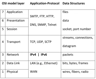
[image:21.612.139.475.176.451.2]stack. Each layer has a related protocol or application and relates to a kind of data structure or representation.
Table 3. OSI Model and related protocols and data structures
OSI model layer Application-Protocol Data Structures
7 Application
SMTP, FTP, HTTP, DNS, SNMP, Telnet
files
6 Presentation data
5 Session socket, port number
4 Transport TCP, UDP, SCTP
streams, connections, datagram
3 Network IPv4 | IPv6 packets 2 Data Link LAN (e.g., Ethernet)
WAN
bits, bytes, frames 1 Physical wires, fibers, radio
Internet protocol is the technology that allows disparate networks to communicate. It sits between local area network technologies like Ethernet and connection orientated
8
network technologies such as Ethernet and it will carry common transport protocols such as TCP and UPD in a similar manner as IPv4.
1.3.3 IPv6 packet architecture compared to IPv4
IPv6 presents a new and streamlined header format for IP packets. IPv6 specifies a fixed size packet header which includes a much larger address capacity and removes parts that were redundant or used infrequently.
IPv6 packet components (number of bits) IPv4 packet components (number of bits)
# of Bytes
Figure 1. Comparison of IPv6 and IPv4 packets
The first four bits of either IP header represent the version number which will guide any processing algorithm. Header length in IPv6 has been fixed at 40 bytes as compared to the variable length available with IPv4 of 20 to 60 bytes, so in IPv6 there is not any HLEN tag. The IPv6 header replaces “service” with “traffic class” and “flow label.” These are designations designed to assist with the management of quality of service or priority for certain Internet
Ver(4) 4 Ver(4) Hlen(4)
8 Flag(3) 12 16 20 24 28 32 36 40 44 48 52 56 60 …
payload … continues Nxt Header (8) Head Len (8) payload …
payload … continues
Nxt Header (8) Head Len (8) payload … payload … continues
Header Options (optional)
Nxt Header (8) Head Len (8) payload … payload … continues
Nxt Header (8) Head Len (8) payload …
Frag Offset (13) TTL (8) Protocol (8) Head. Chcksum(16)
Source Address (32) Destination Address (32) Nxt Header (8) Hop Limit (8)
Service (8) Total Len.(16) Identification (16)
Source Address (128)
Destination Address (128) Flow Label (20) Traf Class(8)
9
traffic. Payload length in IPv6 describes the length of the packet (header plus data payload) where IPv4 had the Total Length flag.
1.3.3.1 Fragmentation in IPv6 is specified by a special type of extension header
The fragmentation options, originally part of the IPv4 header, are designated as one of the extension headers in the IPv6 header
[2]
. Fragmentation occurs when IP packets are larger than the data link layer packet size or MTU (minimum transfer unit) of a network segment that they traverse. IP packets that are larger than a given data link MTU must be broken down into smaller pieces and then eventually reassembled at their destination. An IP packet will traverses various data links with different MTUs as it flows across the global Internet. The links with the MTUs smaller than the IP packet’s actual size are critical in this process.Ethernet, for example, typically has a data link layer size of 1500 bytes. The minimum packet size for an IPv6 datagram is 1280 bytes but can be as large as 65,535 bytes, or even larger if the jumbo gram option is used. When IP datagrams are larger than 1500 bytes, Ethernets maximum packet size, fragmentation is required.
10
1.3.3.2 TTL has been replaced by Hop Limit
The Time to Live or TTL flag from the IPv4 header has been replaced by the Hop Limit flag in the IPv6 header. Both exist as a means to prevent IP datagrams from being routed around the Internet indefinitely. Hop Limit in IPv6 formalizes this descriptor and specifies the maximum number of routers that an IPv6 packet may traverse a before it is dropped.
1.3.3.3 Next Header or Protocol and checksum
The IPv6 includes a “next header” indicator which is similar to the “protocol” flag in the IPv4 header. “Next header” describes the protocol of the payload of the particular IP packet. I will elaborate on the various types of protocol codes in a subsequent section. In the IPv6 header there is no checksum flag. The functionality of a checksum, to verify the integrity of the IP header and payload, is redundant with the functionality in other lower or upper level
networking components e.g., data link or transport layers. With IPv4 routing the checksum has to be evaluated and recalculated at each router along the way. Removing the checksum
requirement from the IPv6 header is intended to improve routing performance by illuminating this unused integrity check.
1.3.3.4 Address specification
11
1.3.4 IP address representation and assignment
Digital representations of either IPv4 or IPv6 addresses as a string of ones and zeros are too cumbersome for humans to deal with so shorthand notations have been developed. IPv4 represents a 32 bit address with a string of four, base ten, numbers ranging from 0 to 255 separated by decimals, e.g., 192.168.100.130. Each base ten number element represents 8 bits. IPv6 represents a 128 bit address with a string of, up to 8 groups, of 4 each, base 16 (or hex) digits, separated by colons ( : ), e.g., fe80::d0g0:bafd:c706:6574. With this notation for IPv6, strings of two or more zeros can be represented by a double colon (: :).
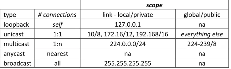
IP addresses are allocated or assigned by a registration process coordinated by the Internet Assigned Numbers Authority or IANA. It is assumed that certain IP address numbers will be used for certain purposes and scopes. It is also possible for a computer to have several network interfaces. In the case of IPv4 networking, one computer network interface usually has one IP address or node. IPv6 extends this concept; in fact most IPv6 nodes will have multiple addresses relating to the scope or type of the communication that is assumed. Figure 2 shows the various types of addresses and examples of prefixes for each.
Types and examples of IPv6 addresses
128 bits represented by 8 groups of 4 each base 16 digits separated by colons (:)
scope
type # connections link - local global
loopback self ::1 na
unicast 1:1 FE80::/10 2000::/3
multicast 1:n FF00::/8 tbd
anycast nearest tbd tbd
12
Types and examples of IPv4 addresses
32 bit represented by 4 groups of 3 each, base 10 digits separated by dots (.) scope
type # connections link - local/private global/public
loopback self 127.0.0.1 na
unicast 1:1 10/8, 172.16/12, 192.168/16 everything else
multicast 1:n 224.0.0.0/24 224-239/8
anycast nearest na na
[image:26.612.71.440.103.213.2]broadcast all 255.255.255.255 na
Figure 2. Types and examples of IPv6 and IPv4 address prefixes
Network communications may occur within a host computer. One way a computer can communicate with itself using networking technology is by using the “loopback” address. This is just one IP address number that has been set aside to mean “this computer.” The loopback address for IPv6 is “::1.” With IPv4 the loopback address is “127.0.0.1.” Loopback addresses are useful for diagnostic or development purposes.
Unicast addresses are used for communications between two nodes or computer devices on a network and referred to as 1 to 1 communication. The most basic form of a computer network is two or more computers sharing a local area network (LAN) or data link technology such as Ethernet. IPv6 specifies a “link-local” address starting with the prefix”FE80” and is configured automatically using the network interface’s media access control or MAC address as a suffix [17]. A MAC or IEEE 802 address is a unique 48 bit number programmed into the network electronics. The link-local address is intended to be used for a device to
13
global Internet. IPv6 link-local and global addresses are like the “private” and “public” in IPv4 systems.
IPv6 expands the capability for multicast addresses. Multicast is a method of message transmission where one computer node sends messages to multiple nodes. Computer nodes must first join a multicast group and agree to share messages. IPv4 has multicast capability but it never really caught on. IPv6 offers additional multicast addresses and their use is being promoted for applications such as video conferencing, entertainment content distribution and system administration. Sometimes multicast is used by a group of routers within a network system.
IPv6 adds a type of address called “anycast.” This is an address type used to connect to or commutate with the nearest or first responding device of some type or category. For example, a node may want to contact the nearest router or shared network printer.
14
1.3.5 Next header or protocol codes
The primary task of the Internet Protocol header is to serve as a “wrapper” or container for some other message data, e.g., Transport datagram. The Internet Protocol packet consists of the header and the payload of other protocol data. The contents of the payload of a given Internet protocol packet are indentified by the “Next Header” tag in the IPv6 header and the “Protocol” flag in the IPv4 header. The “Next Header” or “Protocol” flags are information used by packet filtering firewalls after the address.
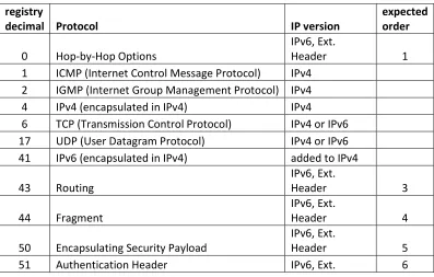
[image:28.612.108.505.464.717.2]Table 4 displays the code decimal number and the protocol name represented by that number and a descriptor of what IP version the protocol applies to [18]. Some of the IPv6 “next header” protocols are designated as extension headers. These can be nested or encapsulated in each other. The recommended order for this nesting is described in the last column.
Table 4. Codes: IPv4/Protocol and IPv6/Next Header
Codes : IPv4 - Protocol and IPv6 -Next Header
registry
decimal Protocol IP version
expected order
0 Hop-by-Hop Options
IPv6, Ext.
Header 1
1 ICMP (Internet Control Message Protocol) IPv4 2 IGMP (Internet Group Management Protocol) IPv4
4 IPv4 (encapsulated in IPv4) IPv4
6 TCP (Transmission Control Protocol) IPv4 or IPv6 17 UDP (User Datagram Protocol) IPv4 or IPv6
41 IPv6 (encapsulated in IPv4) added to IPv4
43 Routing IPv6, Ext. Header 3 44 Fragment IPv6, Ext. Header 4
50 Encapsulating Security Payload
IPv6, Ext.
Header 5
15
Header
58 ICMPv6 IPv6
59 No Next Header IPv6
60 Destination Options
IPv6, Ext.
Header 2, 7
Hop-by-Hop Options, indicated by next header 0, are intended to be information for routers along the path between a source and destination. IP version protocol encapsulation, protocol 4, is possible providing support for tunneling through networks. IPv4 packets can be encapsulated in IPv4 packets as indicated by protocol code 4. IPv6 packets may be encapsulated in IPv4 packets indicated by protocol code 41 [19].
Transmission Control Protocol or TCP and User Datagram Protocol or UDP transport packets can be encapsulated in IPv6 packets just like with IP4 packets. The next header codes for TCP and UDP in IPv6 are the same as the protocol codes in IPv4, 6 and 17 respectively. Routing headers are specified by code 43 and Fragment headers specified by code 44.
Encapsulated Security Payload, an encrypted payload is specified by code 50 and authentication header, used for authentication and integrity is specified by code 51.
IPv6 includes a revision to Internet Control Message Protocol or ICMP which can be specified by next header 58. Code 59 means that there is no next header and Code 60 provides the option for destination options or a kind of “read me first” payload.
16
filter firewall rules but in actuality are like Virtual Private Network or VPN features. I expect that ordinary network services will use TCP or UDP transport protocols and not extension headers.
1.4 Security concerns for IPv6
“Burdensome” is the term used to describe the task of developing and implementing firewall rules for the possible extension headers within IPv6 packets by Caicedo, Joshi, and Tuladhar in the 2009 article “IPv6 Security Challenges” [20]. These authors point out the
requirements for some ICMPv6 messages and the fact that nodes will most likely have multiple IPv6 addresses such as link-local, global, and possibly multicast making administration more challenging. IPv6 promises opportunity but brings complexity and risk. Transition mechanisms such as those described in RFC 2893 will make it possible for IPv6 tunnels to be created over existing IPv4 networks [19]. It is important to consider what can be done with IPv6 despite these significant security risks. Widespread deployment of IPv6 will require mitigation of these issues through trading off features and flexibility.
1.5 Implications of research
17
1.6 Hypothesis:
Operating systems have for many years offered improving levels of support for IPv6
networking. I expect that host based firewall applications are available that can easily
apply protocol filtering and address rules to both IPv4 and IPv6 interfaces.
1.7 Summary
IPv6 is a protocol designed for the next generation of Internet communication. It comes with a simpler format and contains a much larger address capacity necessary for future growth of Internet service provisioning.
IPv6 includes addressing schemes for local, group, any and global Internet
communications which may reside on the same network interface making managing these interface more challenging. IPv6 expands the IP packet payload options by including a series of extension headers that cover functions such as intermediate routing, fragmentation,
confidentiality, authentication, and destination options. IPv6 packets will carry the commonly used TCP and UDP packets over existing local area network technologies such as Ethernet.
18
2
Related work
Research on IPv6 has moved through various phases from early experimental network testing to more recent security issues. Firewall testing with automated means can be found in a report from 1999. A method for firewall/routing IPv6 tunnels over IPv4 was published in 2002. More recent research has focused on the security of IPv6. I believe the focus on security of IPv6 in recent years is a leading indicator for eventual widespread IPv6 deployment.
2.1 “Evaluation and testing of Internet firewalls,” 1999
Al-Tawil and Al-Kaltham describe an approach to test a firewall using various configurations including single and simultaneous testing with attacks coming from within neighboring networks or rogue sources [21]. The authors use both automatic and subjective means to evaluate two different firewalls. This work provides a methodology for evaluating packet filter firewalls that includes variable architectures and an automated packet generation tool called Security Administrator's Tool for Analyzing Networks or SATAN. SATAN was used to interrogate individual host servers to evaluate packet filter firewall effectiveness.
2.2 “IPv6 Firewall with OpenBSD,” 2002
19
described in RFCs 4213 and 2893 and cover the combinations of Router to Router, Host to Router, Host to Host, and Router to Host. These are interesting solutions to connect IPv6 islands through existing IPv4 networks.
Within this publication Millican reviews useful approaches to packet filter firewalling including recommendations to; “block all and permit only what is required” as a default policy, using logging, stateful TCP filtering, and return of reset error messages to mask the firewall presence. Millican includes a list of protocol and ports numbers to explicitly block. This is functionally redundant but allows for recording or logging of specific attacks that the firewall may encounter. In addition, an administrator can have the extra confidence that a known attack is blocked. Packet filter rules are organized by incoming or ingress and outgoing or egress rules. Millican includes rules to allow certain ICMPv6 packets, contained in IPv6 packets for error reporting, MTU, and neighbor discovery. This is a fairly sophisticated example of a firewall that provides tunneling of IPv6 over IPv4 and comprehensive packet filter rules.
2.3 “IPv6 Packet Filtering,” 2005
20
2.4 “Packet Filter Algorithm to prevent the security hole of routing header in IPv6,” 2006
Lim, Kim, and Kim describe the vulnerability introduced with the routing extension header, an option for IPv6. They demonstrate a condition where and IP packet can be routed around a typical firewall that reads only one, actual destination address [15]. If a routing header extension is applied within an IPv6 packet the destination address may represent an
intermediate destination and not necessary a final address. A routing extension header can contain a list of destination addresses with the last one as the real, “final” destination address. Lim, Kim, and Kim propose a network firewall algorithm that reads all of the encapsulated destination addresses and applies an access control list to them.
2.5 “Security aspects in IPv6 networks – implementation and testing,” 2007
Zagar, Grgic, and Rimac-Drlje describe security threats to IPv6 networks such as reconnaissance attacks, routing headers, fragment headers denial of service attacks, IPCMv6 spoofs, the risks of tunnels, and potential holes in dual stack approaches [24]. The authors tested the effectiveness of IPv6 firewalls on two systems, Mandrake Linux 10 and Windows XP using Network Mapper or nmap, an open source, port, and vulnerability scanner. They also simulated an intrusion detection approach using Ethereal, an open source packet capture application.
2.6 “Firewall Design Considerations for IPv6,” 2007
21
header will improve intermediate router efficiency but emphasizes the possible obscurity for packet filter firewalls due to extension headers. Efficiency improvements as described by Potyraj include; removal of checksum, streamlining and fixed size of header, extension header approach, and movement fragmentation from router to originator. The vulnerabilities
introduced by extension headers such as routing, fragmentation options, and tunneling are described in detail through various case scenarios. Potyraj offers several recommendations to address the vulnerable scenarios possible with IPv6’s extension headers.
2.7 “Design and Implementation of Distributed Firewall System for IPv6,” 2009
Lai, Jiang, and Yang describe an approach to use both a network and host firewalls working together to provide security in IPv6 systems [26]. Their approach is targeted for IPv6 packets that contain the Encapsulated Security Payload, or ESP extension header. With IPv6, nodes can set up essential virtual private networks or VPNs between themselves by implement the ESP header. For IPv6 packets that use ESP, the content of the packet is only understandable to the source and destination nodes that have the secret decryption key. This makes firewalls unable to inspect packet contents to apply policy or packet filtering criteria since they can only see source and destination address on encrypted packets. Lai, Jiang and Yang suggest
22
2.8 “Guidelines on Firewalls and Firewall Policy,” 2009
Scarfone and Hoffman from the National Institute of Standards published a guideline for firewalls [11]. This is a revision of a 2002 document which provides a comprehensive practical tutorial and guide for the development of policy and firewall systems. The 2009, revision 1 Guidelines includes a section on recommendations for IPv6 which recommends that; IPv6 firewalls have the same rules available as with IPv4; that tools offer a cloning rule feature to ease the process of making IPv6 filtering rules from existing IPv4 rules, provide capability for managing ICMPv6 content, and a means to filter IPv6 tunnels over IPv4.
2.9 “IPv6 support in firewalls,” 2009
Håkan Lindberg and Tomas Gilså of the .SE, the organization that coordinates Sweden’s top level domain, tested a variety of firewall appliance devices for IPv6 in both 2008 and 2009 [27]. Their tests in 2008 involved only an IPv6 environment whereas the tests in 2009 included test with both IPv4 and IPv6 servers. Their testing included multiple sessions and file sizes from the same IP address for the firewall under test. They used download time as an indication of the firewall device’s ability to process or filter the packet flows. For the six devices tested in 2009 their conclusions were that in general the firewall devices offered comparable features and performance for either IPv4 or IPv6 networking.
2.10 Summary
23
Past work confirms support within operating systems for packet filter firewalls and
24
3
Approach and Methodology
Various organizations have developed approaches to testing and certifying firewall effectiveness. This allows for more confidence in their effectiveness and standard practices in the industry. Common Criteria and ICSA labs provide guidelines from which I derive criteria for my research.
3.1 Common Criteria
The “Common Criteria” (or CC) and “Common Evaluation Methodology for Information Technology Security Evaluation” (or CEM) are the basis for an international agreement called “The Common Criteria Recognition Agreement” (or CCRA). The CCRA maintains, “The Common Criteria,” “Common Evaluation Methodology,” related documentation, a registry of certified independent laboratories, database of “Protection Profiles,” and a listing of certified products [28].
The “Common Criteria” is described by three parts in three documents. The first
document/part is called “Introduction and General Model” and mentions that a Firewall may be a Target of Evaluation (or TOE) and may be used as a counter-measure [29]. The second
document/part, “Security Functionality Requirements” provides very broad requirements for authentication, auditing, cryptography, and access controls. Firewalls are mentioned to be used for IP packet flows or addresses with external interfaces [30]. The third document/part
25
[31]. It also defines “Evaluation Assurance Levels” or EALs. These are used to rate the security level of the computer security product.
[image:39.612.97.546.306.681.2]A document called, “Common, Evaluation Methodology” (CEM) provides guidance for; TOE testing, the development of “Protection Profiles” and reporting of test results [32]. The “Firewall Protection Profile” provides specific description of security threats that a firewall should address [33].
Table 5. Threats listed in the “Firewall Protection Profile” [33]
Threat Description
1. Address spoofing The ability or threat of an external or internal node to use a ‘fake’ or unassigned IP address
2. Continuous
Authentication Attempts
The ability or threat of an external node to repeatedly attempt to access internal resources, e.g., login
3. Illegal Information Inflow The act of illicit information coming from an external source
4. Illegal Information Outflow
The act of information coming from an internal source to an external destination that is not authorized or allowed
5. Impersonation The threat of an external entity masquerading as an authorized user
6. Recording Failure The threat of an external source exhausting the firewalls ability to record events
7. Replay Attack The threat of an external source intercepting and replaying a valid authentication sequence
26
3.2 ICSA Labs Network Firewall Testing Criteria
ICSA Labs offers certifications specifically for firewalls, intrusion detection, virus, and spyware related products. ICSA describes itself as “providing credible, independent, 3rd party product assurance for end users and enterprises” [34].
[image:40.612.67.547.333.632.2]The Modular Firewall Certification Criteria, Baseline module – version 4.1 published by the ICSA provides a set of requirements that are described in Table 6 [35] which are relevant to research on firewall effectiveness.
Table 6. Categories of Criteria from ICSA “Modular Firewall Certification Criteria” [35]
Category Description
1. Logging Firewalls ability to record certain events and details
2. Administration Ability to configure settings or functions
3. Persistence Level of resiliency when power is lost and reapplied
4. Functional Testing Tests enforcement of security policy and administrative functionality under “normal” operating conditions
5. Security Testing Evaluation of the security of the device; including administrative access, vulnerability, denial of service and fragment testing 6. Documentation Installation, Administration (operation/maintenance), Support
documents
27
3.3 A criteria for evaluating the effectiveness of packet filter firewall applications
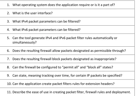
[image:41.612.103.550.354.669.2]“The Common Criteria” and the ICSA publications a comprehensive basis for the evaluation of firewall devices from which I can take a subset of criteria for evaluating packet filters, namely “Illegal Inflows” from the Common Criteria and “Functional” aspects from the ICSA. Packet filtering is one function of a firewall device and a primary means of determining illegal inflows or outflows based on packet characteristics. In order to objectively evaluate packet filter firewalls in a dual stacked environment, I developed the following qualitative criteria.
Table 7. Snyder’s criteria for evaluating “dual stack” Internet Protocol firewall applications
1. What operating system does the application require or is it a part of? 2. What is the user interface?
3. What IPv4 packet parameters can be filtered? 4. What IPv6 packet parameters can be filtered?
5. Can the tool generate IPv4 and IPv6 packet filter rules automatically or simultaneously?
6. Does the resulting firewall allow packets designated as permissible through? 7. Does the resulting firewall block packets designated as inappropriate? 8. Can the firewall be configured to “permit all” and “block all” states? 9. Can state, meaning tracking over time, for certain IP packets be specified? 10.Can the application create packet filters rules for extension headers?
28
My first two criteria relate to the operating system and user interface for the packet filter application under test. The next few criteria relate to the filtering features and how
automatically they can be applied across both IPv4 and IPv6 interfaces. The next few criteria ask how effective the packet filter firewall, created by the application under test, is at allowing and blocking certain IP packets as well as switching to a “permit all” and “block all” states. The last few points ask about the application under test’s ability to deal with tracking of connection state, extension headers (for IPv6 only) and description of the ease of use for developing and deploying the packet filter firewall.
3.4 Summary
29
4
Experiment
I tested two different systems for their ability to create and deploy packet filter firewalls for IPv4 and IPv6 networking against the previously described criteria.
4.1 Experimental system and packet filter firewall applications under test
[image:43.612.122.490.252.476.2]I used the following test platform to conduct my experiments.
Figure 3. Experimental system
30
configured by a different host application to allow access to certain running services while blocking others.
The system was built using a physical, laptop workstation running two other hosts inside VMware Workstation 6.5.1. The real laptop system functioned as the “Observer Host” and two virtual systems “Server Hosts” were deployed and connected using the VMware virtual networking. Initial tests confirmed that the virtual Ethernet networking inside VMware Workstation 6.5.1 supported both IPv4 and IPv6 addresses. For one server host I chose Fedora Core 10 and for the other I chose Windows Server 2008. Both operating systems support dual stack IPv4, IPv6 networking and come with applications for packet filter firewalling.
4.1.1 system-config-iptables in Fedora Core 10
Fedora Core 10 is an open source, Linux operating system that is offered by Red Hat Inc. Support for IPv4 has been included since it began and support for IPv6 has been included since Fedora Core 6 [37]. The “system-config-firewall” is a graphical user interface tool within Fedora Core operating systems which provides basic configuration of firewall rules [38]. System-config-firewall creates configuration files for “iptables” which are used by “netfilter” the network portion of the Linux kernel.
4.1.2 Windows Firewall with Advanced Security in Windows Server 2008
31
Server ® 2008 R2 operating system that blocks incoming or outgoing connections based on the configuration of a rule set [41].
4.2 Scope and firewall test application
I limited the scope of testing and selected a subset of all the possible combinations of IP addresses, protocol and port numbers. For IP addresses, I chose to work with each host’s link-local address since these were configured by default and I had no router in my experimental system.
4.2.1 Transmission Control Protocol (TCP)
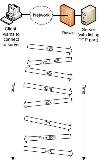
The choice of transmission control protocol is important because each comes with certain expectations or assumptions when it comes to testing an IP protocol and packet filter firewall. I chose to work with TCP (transmission control protocol) because it is very common and can be encapsulated with both IPv4 and IPv6 protocols. TCP is used in file exchanges and hyper text protocol (http) for web pages where assurance in data transfer is required. TCP payloads offer an advantage when it comes to firewall testing since it assumes a formal dialog process to establish and maintain communication. Other transport protocols, such as User Datagram Protocol or UDP, send data without this formal exchange or verification process.
32
[image:46.612.200.406.169.506.2]ends with a closing three way handshake described in figure 4. TCP provides a high level of certainty that messages are sent and received. The “syn” message starts the conversation between the two computers.
Figure 4. TCP’s “three way handshake” process
4.2.2 Modeling the TCP/IP packet filtering process
33
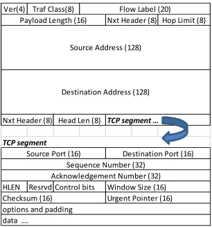
Figure 5. An IPv6 packet with a TCP protocol payload
A basic packet filter will inspect the following header fields; Next Header for the protocol designation of the payload, Source, Destination IP Address, and within the TCP data payload, the source and destination port number. State-full packet filters may look at sequence, acknowledgement, as well as control bits and window size and compare this to past
information to insure continuity.
Ver(4)
HLEN Resrvd
data ….
TCP segment
Window Size (16) Control bits
Checksum (16) Urgent Pointer (16)
options and padding
Source Port (16) Destination Port (16)
Sequence Number (32) Acknowledgement Number (32)
Source Address (128)
Destination Address (128)
Nxt Header (8) Head Len (8) TCP segment …
Traf Class(8) Flow Label (20)
34
Figure 6. Modeling firewall operation
It is possible to model the process of one computer connecting to another with a packet filter firewall in place. A client sends an IP packet/message to a destination, a server in this case, through the network. The packet is addressed to the server’s port 80 and contains a TCP protocol payload. The network interface on the server receives this packet and passes it to the firewall. The firewall reads the source and destination IP addresses protocol, and source and destination port numbers. It compares these to a list of allow and deny rules. If the packet is allowed it is permitted to pass to the host and handed off to the “listening socket” (a computer process/program in a wait mode) corresponding to the destination port number. If the packet is “not allowed” it is dropped and an ICMP error message may be sent back to the requesting client.
35
4.2.3 Port number assumptions
[image:49.612.159.454.294.547.2]Each IP address may have one or more ports available with a certain transport protocol assumed. Ports and transport protocol are the technology that computer applications use to transfer data across the Internet. There are 65,536 ports possible and popular transport protocols include TCP and UDP. Table 8 describes popular port numbers, protocol, and the applications or services associated with each summarized from Forouzan [42] .
Table 8. Well known port numbers used with TCP transport protocol
Port Protocol Description
20 FTP File Transfer Protocol, data 21 FTP File Transfer Protocol, control 22 Telnet Terminal Network
25 SMTP Simple Mail Transfer Protocol 53 DNS Domain Name Server
67 BOOTP Bootstrap Protocol
DHCP Dynamic Host Configuration Protocol
80 HTTP Hypertext Transfer Protocol 111 RPC Remote Procedure Call
433 HTTPS HTTP over Secure Sockets Layer
4.2.4 Port scanning/connectivity tool - Nmap
36
initial “syn” message, nmap figures out whether or not a firewall is in place and whether or not a given port is accessible. My research indicated that nmap had IPv6 capabilities [24]. In my testing I put nmap on the “Observer Host” and used it to send a series of “syn” messages to a wide range of port numbers to check each server. Nmap makes a determination to the status of each port based on the response to each “syn” message that it sends to a given host. A
[image:50.612.148.465.323.555.2]summary of the possible responses and a description of their meaning is enclosed in the following table.
Table 9. “nmap” interpretation of response to “syn” request
message returned from server host
“nmap” interpretation
… port is description
syn + ack open
host is up, port open and listening
reset closed
host is up, no application on port
icmp error filtered firewall filter in place
no response
filtered or down
firewall filtered and set to no response or host is down
37
4.3 Experimental Steps
My experimental procedure consisted of six parts; install and configure a “Server Host” system, deploy a packet filter firewall using the application under test, confirm listening services on the host server, then test the firewall in three states: “as designed,” “permit all,” and “block all” using nmap port scanning.
4.3.1 Install and configure “Server Host” system
Operating systems were installed on each virtual host computer system following guidelines provided with the intent of creating a web server with remote login and adding four custom netcat processes. I installed services on each server host for Internet web server and remote login access capabilities. On each server I also installed and then ran four instances of the application “netcat.” “Netcat” is an open source tool for either Windows or Linux that can function as a client or server using TCP on either IPv4 or IPv6 addresses [43]. Two “netcat” servers were installed and bound to server’s IPv4 address and two were installed and bound to the server’s IPv6 address. The plan was that one of each IP version of the netcat process would be blocked by the firewall and the other allowed.
4.3.2 Deploy a packet filter firewall using the “application under test”
38
4.3.3 Confirm listening services on “Server Host”
To display all the running and listening services on each server I used “netstat.” “Netstat” is a command line tool available on either Windows or Linux that displays lists of running networked processes, their mode, e.g., “listening,” and the IP address and port number that they are bound and recently connected to (a external/foreign IP address).
4.3.4 Connectivity of “Server Host” with firewall “as designed”
After the firewall was deployed on each “Server Host,” it was tested using nmap from the “Observer Host.” Nmap sent a series of “syn” messages to the ports on each the server hosts and interprets the response.
4.3.5 Connectivity of “Server Host” with firewall in “accept all” and “block all”
To be sure the firewall was actually running the designed firewall state; two other firewall states were included in my testing process, “accept all” and “block all.” “Accept all” provided verification for “netstat,” meaning the “observer host” should see all the listening processes on the server. “Block All” confirmed the firewall’s ability to shut down the interface to any network connection.
39
5
Results
5.1 System-config-firewall/iptables on Fedora Core 10/Linux
My first test case was with “system-config-firewall” and “iptables” using Fedora Core 10 a Linux based operating system.
5.1.1 “Server Host” and “Observer Host” configuration
I installed and configured a “server host” using Fedora Core 10, Kernel Linux 2.6.27.41-170.2.117.fc10.i686 runing inside VMWare© Workstation 6.5.1 build-126130. I also installed and configured to run at boot the following services: secure shell (ssh/22), domain name service (dns/53, light-weight dns, dnsmasq) and Apache web server (http/80, https/443). I installed netcat and added four Netcat services, 2 IPv4 and 2 IPv6 by typing the following
commands: “nc – 4 –l 741&, nc – 4 –l 742&, nc – 6 –l 761&, nc – 6 –l 762&.” I also experimented briefly with the service “sendmail.” It was installed but it was configured to a local host address, meaning it would not be addressable through a networked IP address.
The server host received its IPv4 address from a DHCP server running inside the VMware ethernet and was IP addresses: Ipv4: 192.168.100.130. Fedora Core 10 will automatically
configure an IPv6 address on its interfaces using a generic prefix and the interface’s MAC address. The link-local address for the Server host was IPv6: fe80::20c:29ff:fe7b:eb64.
oberserver host obtained a link-local address of IPv6: fe80::106c:f7c9:b2f3:9019%16 by self autoconfiguration.
5.1.2 Creating a packet filter firewall using “system
I launched system-config
control panel. I was presented with the following screen.
Figure 7. “Trusted Services” window, system
From the “Trusted Services” allow through the packet filter firewall.
port numbers 53. For my testing I ignored UDP ports as they are more complex included sendmail (port 25/tcp)
be filtered, but there will not be an
was able to select web services ssh/22 and
From the “Other Ports” screen, I entered access for
e.g., ports 742 and 762. The application assigned a service name to these ports which is not accurate for my case but probably comes from the IANA port assignment
40
local address of IPv6: fe80::106c:f7c9:b2f3:9019%16 by self
Creating a packet filter firewall using “system-config-firewall”
config-firewall.py 1.2.16, copyright 2007-2009, Red Hat Inc. from the control panel. I was presented with the following screen.
. “Trusted Services” window, system-config-firewall
From the “Trusted Services” window I was able to select the service which I wanted to allow through the packet filter firewall. By selecting DNS, I received both TCP and UDP protocol
For my testing I ignored UDP ports as they are more complex
to test “closed” port detection capability of nmap. Port 25 will be an active process bound to either IPv4 or IPv6 addreses
ssh/22 and http/80 from the “Trusted Services”
From the “Other Ports” screen, I entered access for two of my four netcat
The application assigned a service name to these ports which is not case but probably comes from the IANA port assignment listing
local address of IPv6: fe80::106c:f7c9:b2f3:9019%16 by self
2009, Red Hat Inc. from the
I was able to select the service which I wanted to both TCP and UDP protocol For my testing I ignored UDP ports as they are more complex to test. I
of nmap. Port 25 will process bound to either IPv4 or IPv6 addreses. Also, I
from the “Trusted Services” window.
two of my four netcat processes, The application assigned a service name to these ports which is not
Figure 8. “Other Ports” window, system
Lastly, I looked at the ICMP Filter screen since especially ping so I could verify connectivity.
Figure 9. “ICMP Filter,” system-config firewall
The “ICMP Filter” window was the first time I was presented with any information that indicated this tool would affect both IPv4 and IPv6 packet filtering.
check items for the firewall to reject.
clicked on “Apply” which saves these settings to these settings active.
41 . “Other Ports” window, system-config-firewall
ooked at the ICMP Filter screen since I was interested in allowing ICMP traffic, especially ping so I could verify connectivity.
config firewall
The “ICMP Filter” window was the first time I was presented with any information that both IPv4 and IPv6 packet filtering. This screen allowed
the firewall to reject. I left them all unchecked. After making these settings I clicked on “Apply” which saves these settings to a configuration file and makes a firewall with
I was interested in allowing ICMP traffic,
The “ICMP Filter” window was the first time I was presented with any information that This screen allowed me to I left them all unchecked. After making these settings I
42
This user interface is straightforward and convenient but I discovered two major problems. System-config-firewall creates a ruleset with two lines that severly compromise firewall effectiveness. One line allows established connection packets to pass the firewall and a second line allows ALL packets to pass the firewall. This problem was only discovered after careful analysis of the configuration file created by system-config-firewall and review of how the underlying “iptables” commands work. The details of this problem and my corrective action to remove these lines are described in Appendix A.
Another significant issue with this tool was trying to understand the relationship it had to the system and other command line tools like “service” and “iptables.” I ended up creating a system state diagram in oder to have a comprehensive picture of how the various elements went together which is also in Appendix A.
5.1.2.1 Displaying the active packet filter rules created by system-config-firewall
Figure 10. Output from "service iptables status," Fedora Core
Figure 11. Output from "service ip6tables status," Fedora Core
The columns of information displayed show the rule number, the target (which is another name for the resulting action that will occur if the criteria in the rule is true), the protocol of the incoming packet,
address, 0.0.0.0 or :: ), the destination
43
. Output from "service iptables status," Fedora Core
. Output from "service ip6tables status," Fedora Core
information displayed show the rule number, the target (which is another name for the resulting action that will occur if the criteria in the rule is true), the
packet, the source IP address (which in this case is any IPv4 address, 0.0.0.0 or :: ), the destination IP address (which is also any IPv4 or IPv6
information displayed show the rule number, the target (which is another name for the resulting action that will occur if the criteria in the rule is true), the
connection state. (e.g., NEW tcp) , with the specified destination port number. allows ICMP packets to be accepted on this server host.
services I selected in system-config reject rule and was created by system
fails to match up with any of the previous rules. firewall will not block any packets.
sent back to the destination if such a packet is detected or dropped.
that a firewall is in place. The ip6tables display is almost identical to the IPv4 versio address specifications are for IPv6.
also may be created. In this case, system
as this is used by the DNS application in addition to TCP.
5.1.3 Confirming listening services on Fedora Core 10, “Server Host”
I ran “netstat –napt” to observe the listening processes that are using networked connections.
of all processes using tcp transport protocol and their associate process id number.
Figure 12. Inventory of listening services, Fedora Core 44
connection state. (e.g., NEW tcp) , with the specified destination port number. The first rule allows ICMP packets to be accepted on this server host. Rules 2 through 8 correspond to the
config-firewall. The last rule in this list, number 9, is the default and was created by system-config-firewall. It will be applied if the incoming packet
he previous rules. This is a critical rule since if it is not present the firewall will not block any packets. This “reject” rule specifices that an ICMP error messsage be sent back to the destination if such a packet is detected or dropped. This is often
that a firewall is in place. The ip6tables display is almost identical to the IPv4 versio
for IPv6. Both iptables and ip6tables displays any UDP rules which In this case, system-config-firewall created firewall rules for UDP port 53 as this is used by the DNS application in addition to TCP.
Confirming listening services on Fedora Core 10, “Server Host”
napt” to observe the listening processes or services for this server host that are using networked connections. The options I used for this tool provide numeric display of all processes using tcp transport protocol and their associate process id number.
ntory of listening services, Fedora Core
The first rule through 8 correspond to the The last rule in this list, number 9, is the default
It will be applied if the incoming packet This is a critical rule since if it is not present the This “reject” rule specifices that an ICMP error messsage be
This is often a telltale sign that a firewall is in place. The ip6tables display is almost identical to the IPv4 version but the
Both iptables and ip6tables displays any UDP rules which firewall created firewall rules for UDP port 53
![Table 1. Terminology, Portions adapted from RFC 2460 [2]](https://thumb-us.123doks.com/thumbv2/123dok_us/54851.5046/14.612.67.546.96.685/table-terminology-portions-adapted-rfc.webp)
![Table 5. Threats listed in the “Firewall Protection Profile” [33]](https://thumb-us.123doks.com/thumbv2/123dok_us/54851.5046/39.612.97.546.306.681/table-threats-listed-firewall-protection-profile.webp)
![Table 6. Categories of Criteria from ICSA “Modular Firewall Certification Criteria” [35]](https://thumb-us.123doks.com/thumbv2/123dok_us/54851.5046/40.612.67.547.333.632/table-categories-criteria-icsa-modular-firewall-certification-criteria.webp)