Abstract: This paper studies on modeling, simulation with output potential control of KY-POBC using proportional integral controller (PIC). Due to time varying and switching characteristics of KY-POBC and also its dynamic performance is complex. Owing to increase the dynamic characteristics with output potential control of KY-POBC, a PIC is designed. The dynamic equation of the KY-POBC is derived with help of averaging method at first and then PIC is developed using Zeigler-Nichols Tuning method. The analysis of designed controller is verified at different operating conditions via. the transient region, supply voltage variation and the load variation by making MATLAB/Simulink model. The results are showed designed controller proficiency performance at various working regions.
Keywords: Boost converter, PIC, and KY converter.
I.INTRODUCTION
In much low power source application needs good output voltage with minimal ripple voltage. Current days, low ripple voltage-stepping converter topologies is well presented [1-2]. But, these converters have one right-half plane zero (RHPZ) in continuous coil current that is complex in real time implementation. The KY-boost converter has currently established by K.I. Hwu and Y.T. Yau works in continuous current whereas maintaining load current is not pulsating that make the less rate of change of voltage across output capacitor resulting the low load voltage ripples in the range of mV and in addition a very good transient response in the order of few mS [3]. The state space average model for various DC-DC converters was addressed [4]. The PI and SM controllers for various DC choppers were reported [5-14].
Therefore, in this paper, it is designed to control output voltage of KY positive output boost converter (POBC) operated in continuous coil current with the proportional integral controller (PIC). The average model of the KY-POBC is derived at first and then PIC is designed. The performance of controller using KY-POBC is validated at different regions.
Revised Manuscript Received on March 08, 2019.
K.Ramash Kumar, Professor, Karpagam College of Engineering, Department of Electrical and Electronics Engineering, Coimbatore-32, Tamilnadu, India.
S. Balakumar, Department of Electrical and Computer Engineering, Institute of Technology, Arba Minch University, Etothipa.
S. Azath Hussain, Department of Computer Science and IT, Institute of Technology, Arba Minch University, Etothipa.
II.OPERATION AND STATE SPACE AVERAGE MODEL OF KY POSITIVE OUTPUT BOOST
CONVERTER
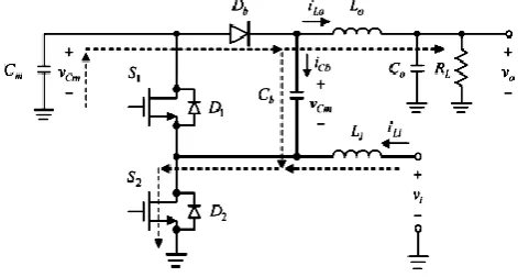
The KY-POBC (refer the Fig.1). The KY-POBC is DC-DC converter operating with voltage conversion ratio of 1 plus d, where„d‟ is the time variant duty cycle of the PWM signal which is controlled by the output voltage of it. It consist of twice coils, S1 and S2 with D1, and D2 and Db with
Cb and Li and L0 with C0. The KY-POBC is operating with
[image:1.595.306.551.301.437.2]state 1 and state 2.
Fig. 1 Topology of KY boost converter
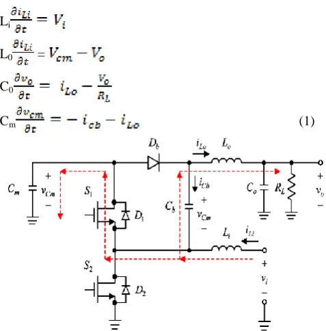
The power flow circuit of the state 1 KY POBC (see fig.2).
Fig. 2 Equivalent circuit of state 1 operation In state 1, switch S1 is open and S2 is closed which ground
the negative terminal of Cb is pulled to the ground that leads
to Db conduct. In this mode, Cm is released energy and Cb is
charged. The VLi = Vi, Li is stored the energy and L0 is
released energy. The icm = icb + iLo. ico = iLo + io. The state 1
working is expressed by the state equations as (1)
Improved Performance of KY Positive Output
Boost Converter using Classical PI Controller
[image:1.595.306.542.484.610.2]Li
L0 =
C0
[image:2.595.47.286.46.288.2]Cm (1)
Fig. 3 Equivalent circuit of state 2 operation In this mode 2 operation (refer Fig.3) S1 is closed and S2
is open that make Db in reverse biased and stores Cm and
release the energy Cb. The voltage across VLi = Vi - Vcm that
Li de-energized and L0 energized, since the voltage across
inductor VLo = 2Vcm - V0. The icm = iLo – io. The icm = iLi –
iLo. The mode 2 working is expressed by (2)
Li =
L0 =
C0 =
Cm = (2)
The mean value of voltage and current can be found from (3), where the variable x is the time-varying parameter and symbolizes voltage or current.
= (3)
The average equation found from (1)-(3) are expressed by (4)
Li =
L0 = (4)
C0 =
Cm =
The voltage transfer gain of KY POBC is expressed as (5)
(5)
Let us choose the state variables of KY-POBC as and its differential equation for the state operation of mode 1 KY-POBC is
=
=
=
= (6)
The differential equation for the state operation of Mode 2 KY-POBC is expressed as,
=
=
=
= (7)
By applying the above equations, the average model of the given system is derived by using the equation (8),
=
(8)
Where,
(9)
The matrix equation for the A, B, C parameters are given as follows,
A =
B= (10)
C =
III. DESIGN OF PIC
Fig. 4 Design of PIC The PIC design has proportional gain (Kp) and Integral
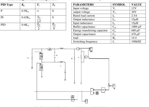
time (Ti) are designed using Zeigler-Nichols tuning method. Zeigler-Nichols suggested to mark the ranges of Kp = 9.316
and Ti=0.0166s according to Table 1 suggested by
Zeigler-Nichols method [14]. Simulink diagram of PIC is shown in Fig. 4.
Table. 1 Zeigler Nichols Tuning Method
PID Type Kp Ti Td
P 0.5Kcr ∞ 0
PI 0.45Kcr 0
PID 0.6Kcr
IV. SIMULATION STUDY
[image:3.595.58.564.350.714.2]The verification of KY-POBC with controller is done for different regions using MATLAB/Simulink (refer fig. 5). A simulation has been performed on the KY-POBC with the parameters listed in Table 2.
Table. 2 Specification of KY-POBC
PARAMETERS SYMBOL VALUE
Input voltage Vi 12V
output voltage Vo 36V
Rated load current Io 2.5A
Output inductance Lo 15µH
Input inductance Li 15µH
Buffer capacitance Cm 1000 µF
Energy transferring capacitor Cb 680 µF
Output capacitance Co 470 µF
load RL 14.4
Switching frequency fs 100kHZ
A. Transient Region
0 0.01 0.02 0.03 0.04 0.05 0.06 0.07 0.08 0.09 0.1 0 0.5 1 1.5 2 2.5 X: 0.006424 Y: 2.002 TIME(SEC) O U T P U T C U R R E N T
OUTPUT INDUCTOR CURRENT
SETTLING TIME=0.0064SEC
[image:4.595.314.507.56.197.2]0 0.005 0.01 0.015 0.02 0.025 30 31 32 33 34 35 36 37 38 39 40 X: 0.006421 Y: 36.02 TIME(SEC) O U T P U T V O L T A G E (V ) OUTPUT VOLTAGE SETTLING TIME=0.0064SEC
Fig. 6 Simulated results of KY-POBC using PIC, (a) inductor current, and (b) output voltage in a transient
region.
Fig.6 (a) and (b) shows the output voltage and the inductor current of PI with KY positive boost converter in transient region. It can be seen that KY-POBC has negligible peak overshoot and settling time of 0.0064 sec.
B. Line Variations
Fig.7 shows the simulated output voltage of KY-POBC with control for the input voltage from 12V to 15V. It is found that KY-POBC has maximum overshoot of 1.13 V and settling time of 0.0041 s with PIC.
[image:4.595.68.270.69.376.2]0 0.005 0.01 0.015 0.02 0.025 30 31 32 33 34 35 36 37 38 39 40 X: 0.00417 Y: 36.04 OUTPUT VOLTAGE TIME(SEC) O U T P U T V O L T A G E (V ) SETTLING TIME=0.0041SEC
Fig. 7 Simulated output voltage of the converter using PIC when input takes step change to 12V to 15V. C. Load Variations
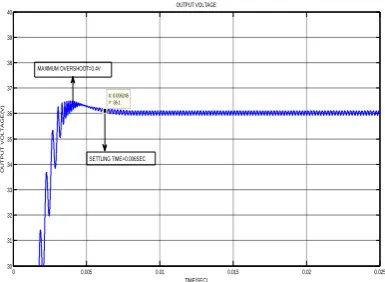
Fig.8 shows the simulated output voltage with R from 18
0 0.005 0.01 0.015 0.02 0.025 30 31 32 33 34 35 36 37 38 39 40 X: 0.006245 Y: 36.1 TIME(SEC) O U T P U T V O L T A G E (V ) OUTPUT VOLTAGE SETTLING TIME=0.006SEC MAXIMUM OVERSHOOT=0.4V
Fig. 8 Simulated output voltage of KY-POBC using PIC for load resistance step change from 18 Ω to 28 Ω In Fig.9 shows that variation of output with step change from 18 Ω to 12 Ω. It could be seen that there is a small overshoot of 0.52V with settling time of 0.006 sec.
0 0.005 0.01 0.015 0.02 0.025
30 31 32 33 34 35 36 37 38 39 40 X: 0.006516 Y: 36.12 TIME(SEC) O U T P U T V O L T A G E (V ) OUTPUT VOLTAGE SETTLING TIME=0.006SEC MAIMUM OVERSHOOT=0.52V
Fig. 9 output voltage of load resistance varies from 18 Ω to 12 Ω.
V. CONCLUSIONS
In this paper modelling, simulation and load voltage control of KY-POBC with PIC has been successfully demonstrated using MATLAB/Simulink. Numerical analysis and simulations are presented to show the proficient of designed PIC for the KY-POBC operated resulted in proficient regulated output voltage in line and load disturbances, good steady state and transient responses etc. It is, therefore, suitable for any stable power source real-world commercial applications.
REFERENCES
1. F. L. LUO AND H. YE, “Negative output multiple-lift push-pull SC
Luo-converters,” IEEE PESC‟03, vol. 4, pp. 1571-1576, 2003.
2. FANG LIN LUO AND HONG YE, “Negative output super-lift
converters,” IEEE Trans. Power Electron., vol. 18, no. 5, pp. 1113-1121, 2003.
3. MAHDAVI, J., EMADI, A., TOLIYAT, H.-A., “Application of state
space averaging method to sliding mode control for PWM DC/DC
converters,” IEEE Industry Application Society Annual Meeting, New
[image:4.595.314.539.288.447.2] [image:4.595.63.270.551.678.2]4. K. I. HWU, W. C. TU AND Y. H. CHEN “A KY Boost Converter ,”
IEEE Trans. Power Electronics, vol. 25, n.11, Nov pp. 2699 – 2703.
5. COMINES, P., MUNRO, N., “PID controllers: recent tuning methods
and design to specification,” IEEE Proc. Control Theory Application,
2002, 149, (1), pp.46-53.
6. R. KALAIVANI, K. RAMASH KUMAR, S. JEEVANANTHAN,
“Implementation of VSBSMC plus PDIC for Fundamental Positive
Output Super Lift-Luo Converter,” Journal of Electrical Engineering,
Vol. 16, Edition: 4, 2016, pp. 243-258.
7. K.RAMASH KUMAR, S.JEEVANANTHAN, S.RAMAMURTHY,
“Improved Performance of the Positive Output Elementary Split Inductor-Type Boost Converter using Sliding Mode Controller plus
Fuzzy Logic Controller,” WSEAS TRANSACTIONS on SYSTEMS and
CONTROL, Vol. 9, 2014, pp. 215-228.
8. K. RAMASH KUMAR, “Implementation of sliding mode controller
plus proporotinal double integral controller for neagtive output elementary boost converter,” Alexandria Engineering Journal, 2016, Vol. 55, No. 2, pp. 1429-1445.
9. RAMASH KUMAR, K., JEEVANANTHAN, S., “Design of sliding
mode control for negative output elementary super lift Luo-Converter
operated in continuous conduction mode,” ICCCCT’10, Tamilnadu,
India, pp. 138-148.
10. S.SENTAMIL SELVAN, K.RAMASH KUMAR, R.BENSRAJ,
“Modeling, Simulation and Design of Variable Structure Based Sliding
Mode Controller for KY-Voltage Boosting Converter,” WSEAS
TRANSACTIONS on CIRCUITS and SYSTEMS, Vol. 15, 2016, pp.143-154.
11. KUPPAN RAMASH KUMAR, SEENITHANGAM
JEEVANANTHAN,” Sliding mode control design for current distribution control in Paralled Positive Output Elementary Super Lift
Luo Converters”, Journal of Power Electronics (JPE) Korea, Vol.11,
No.5, September 2011, pp. 639-654.
12. K. RAMASH KUMAR, S. JEEVANANTHAN, “A Sliding Mode
Control for Positive Output Elementary Luo Converter,” Journal of
Electrical Engineering, Volume 10/4, December 2010, pp. 115-127.
13. K. RAMASH KUMAR, S. JEEVANANTHAN, “Analysis, Design and
Implementation Of Hysteresis modulation sliding mode controller for
negative output elementary boost converter”, Journal of Electric
Power Components and Systems, Vol.40, No.3, 2012, pp. 292-311.
14. K. RAMASH KUMAR, S. JEEVANANTHAN, “PI Control for
Positive Output Elementary Super Lift Luo- Converter,” International
Journal of Electrical and Electronics Engineering, 4:7 2010, pp. 440-446.
15. T. PADMAPRIYA AND V. SAMINADAN, “Improving Throughput
for Downlink Multi user MIMO-LTE Advanced Networks using SINR
approximation and Hierarchical CSI feedback”, International Journal
of Mobile Design Network and Innovation- Inderscience Publisher, ISSN : 1744-2850 vol. 6, no.1, pp. 14-23, May 2015.
16. T. PADMAPRIYA AND V. SAMINADAN, “Inter-cell Load
Balancing technique for multi-class traffic in MIMO-LTE-A
Networks”, International Journal of Electrical, Electronics and Data
Communication (IJEEDC), ISSN: 2320- 2084, vol.3, no.8, pp. 22-26, Aug 2015.
17. S.V.MANIKANTHAN AND V.RAMA“ Optimal Performance Of
Key Predistribution Protocol In Wireless Sensor Networks”
International Innovative Research Journal of Engineering and Technology ,ISSN NO: 2456-1983,Vol-2,Issue –Special –March 2017.
18. S.V.MANIKANTHAN AND T.PADMAPRIYA “Recent Trends In
M2m Communications In 4g Networks And Evolution Towards 5g”International Journal of Pure and Applied Mathematics, ISSN NO:1314-3395, Vol-115, Issue -8, Sep 2017.
19. RAJESH, M., AND J. M. GNANASEKAR. & quot; GCCover
Heterogeneous Wireless Ad hoc Networks .& quot; Journal of
Chemical and Pharmaceutical Sciences (2015): 195-200.
20. RAJESH, M., AND J. M. GNANASEKAR. & quot; An optimized
congestion control and error management system for OCCEM. & quot;