This is a repository copy of Novel design of central dual-receiver for solar power tower. White Rose Research Online URL for this paper:
http://eprints.whiterose.ac.uk/94734/ Version: Accepted Version
Article:
Luo, Y, Du, X and Wen, D (2015) Novel design of central dual-receiver for solar power tower. Applied Thermal Engineering, 91. pp. 1071-1081. ISSN 1359-4311
https://doi.org/10.1016/j.applthermaleng.2015.08.074
© 2015, Elsevier. Licensed under the Creative Commons Attribution-NonCommercial-NoDerivatives 4.0 International http://creativecommons.org/licenses/by-nc-nd/4.0/
eprints@whiterose.ac.uk https://eprints.whiterose.ac.uk/ Reuse
Unless indicated otherwise, fulltext items are protected by copyright with all rights reserved. The copyright exception in section 29 of the Copyright, Designs and Patents Act 1988 allows the making of a single copy solely for the purpose of non-commercial research or private study within the limits of fair dealing. The publisher or other rights-holder may allow further reproduction and re-use of this version - refer to the White Rose Research Online record for this item. Where records identify the publisher as the copyright holder, users can verify any specific terms of use on the publisher’s website.
Takedown
If you consider content in White Rose Research Online to be in breach of UK law, please notify us by
1
Novel design of central receiver for solar power tower
Yan Luo1,2, Xiaoze Du2†, Dongsheng Wen1†
1 School of Chemical and Process Engineering, University of Leeds, Leeds, LS2 9JT
2School of Energy, Power and Mechanical Engineering, North China Electric Power University,
Beijing 102206, China.
Abstract
A novel dual-receiver with a surrounding solar field was proposed to improve the efficiency of
solar power tower (SPT). The new design combined an external and a cavity receiver,
corresponding to the boiling and superheating sections respectively, and provided a simple yet
controllable heat flux distribution on both sections. A case study of a 11MW solar power plant was
conducted. It was demonstrated that the present dual-receiver could produce superheat steam of
515ºC and 10.7MPa at the solar heat absorbing efficiency of 86.55%. By considering various heat
losses, the surface heat flux, the surface temperature, as well as the heat transfer fluid distributiuon
were obtained for the dual-receiver. A comparison with two external cylindrical receivers showed
that the present design could improve the global thermal efficiency by 3.2%. Off-design
performance of the dual-receiver was obtained, which indicated that the plant performance was
affected significantly by the incident solar fluxes at different time of a day. The influence of heat
transfer tube size suggested that an optimized tube diameter for the superheating section of the
present dual-receiver should be used. .
Keywords: solar power tower, dual-receiver, heliostat field, heat loss
2
Nomenclature
A area, m2
a void fraction in cross-section
c specific heat capacity, J/(kg·oC)
d tube diameter, m
G mass flow rate, kg/m2·s
g Gravitational acceleration, m/s2
H enthalpy of heat transfer fluid, J/kg
h heat transfer coefficient, W/ m2 K
l boiler receiver height, m
m mass flow rate, kg/s
Nu Nusselt number
Pr Prandtl number
P pressure, Pa
q incident solar energy flux, W/ m2
Q incident solar energy, W
Re Reynolds number
T temperature, K
u fluid velocity, m/s
x steam quality
Greek symbols
tube wall absorptivity
volumetric thermal expansion coefficient
tube wall emissivity
3
thermal conductivity, W/m·K
dynamic viscosity, N·s/m2
kinematic viscosity, m2/s
density, kg/m3
Subscripts
B boiling receiver
Conv convective heat loss
f heat transfer fluid of one phase
foc forced convection of heat transfer fluid in the tube
gr difference between saturated and superheating parameter
i inner tube
in incident
j surface j
k surface k
lh latent heat
nc natural convective heat loss
rad radiative heat loss
ref reflective heat loss
s superheating receiver
sat saturated state
sl saturated liquid parameters
sub subcooling liquid
sv saturated vapor parameters
4
1 Introduction
Concentrated solar power (CSP) technologies offer promising options for high efficiency solar
energy applications. Of all CSP technologies available, the solar power tower (SPT) can achieve
higher temperatures up to 1000ºC and hence higher efficiency than that of parabolic trough and
linear Fresnel systems [1]. SPT also has the greatest potential for cost reduction and efficiency
improvement among all CSP technologies [1].
Most established solar tower power plants use water as heat transfer fluid (HTF), which is a
mature and cost-effective configuration without extra energy storage [2]. For example, SUNSHING,
Solar One, SPP-5, Beijing Badaling, PS10, PS20 and Sierra were direct steam generation solar
thermal plants [1, 3-6], among which, SUNSHING, SPP-5, PS10 and PS20 were based on saturated
steam, and others used superheated steam [1, 7].
No matter which condition applies, a single receiver on the top of the solar tower is always used
either in the form of external cylinder or internal cavity, which includes both boiling and
superheating sections. It was suggested that for plants capacity of exceeding 50MW with 6 hours of
energy storage, external receiver in combination with a surrounding field should be used, rather
than the cavity configuration with a fixed opening [8]. This was mainly based on the consideration
of heliostat field efficiency, as the cavity configuration requires heliostats much far away from the
tower and hence more atmospheric attenuation loss. A surrounding field is more suitable for large
capacity plants. However, the single receiver design can bring many inherent constrains. For
instance, as there is no saturated steam produced at the beginning of the start-up, it is easy to
produce the overheating problem in the superheating section. This is why several solar tower power
plants only used saturated steam as working fluid. In addition, the difference in the convective heat
transfer coefficient of the two sections requires different allowable heat fluxes. It has been
5
650kW/m2 and 300kW/m2, respectively [9]. Apparently it becomes difficult for the one-receiver
configuration to control proper heat flux distribution on both sections.
Recently, some researchers have investigated the possibility of separating boiling and
superheating sections. A patent was filed in 2011 that comprised two external cylinder receivers in
series, one for boiling section and the other for superheating section [10]. Most recently, a patent
proposed two cavities instead of external cylinders for the two sections [11]. In another
configuration, an integrated receiver was designed that had a boiling section in tandem with a
superheating section [12]. The receiver had a north-faced opening sector of 72º with the outer
surface acting as the boiling section and the inner surface as the superheater. Because both inner
and outer surfaces were heated, there was no suitable place for the downcomer, which was essential
to ensure no vapor produced and hence avoiding the reduction in the fluid circulation velocity. The
inner surface was served as a cavity receiver. However, the opening angle of 72o was so small that
there was almost no incident flux distribution on side wall panels [12]. On the other hand, the inner
surface had no cavity aperture inclination, which was necessary to reduce convective loss.
In order to avoid the problems presently existing, in this study a novel configuration of
dual-receiver for solar tower power plant is proposed by combining the advantages both of the external
and cavity receiver. In the new designed dual-receiver, the top is an external receiver to serve as the
boiling section, and the bottom is a cavity one as the superheating section. The surrounding
heliostat field is correspondingly divided into two parts, focusing lights onto the boiling and
superheating sections, respectively. As a demonstration, the feasibility study of a 11MW solar tower
power plant is conducted in this work, of which the configuration can be extended to larger capacity
plants. It is expected that such a new idea would improve the efficiencies of solar towers by getting
away from the drawbacks of the single receiver and fully utilizing its merits.
6
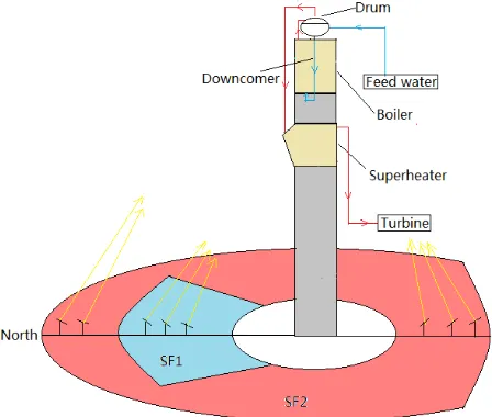
The configuration of the proposed dual-receiver with the schematic surrounding heliostat field is
shown in Fig. 1. Taking water as heat transfer fluid, the top external receiver served as the boiling
section for the solar power plant with a surrounding heliostat field, indicated as SF2 in Fig. 1. As
the boiling temperature, ranged 300-400oC, is relatively low, small convection and radiation heat
losses are expected. The bottom cavity receiver serves as the superheating section, heated by north
heliostat field SF1, shown in Fig. 1. Considering the high superheat temperature typically
encountered, i.e., surface temperature ranges from 300oC to 700oC, a cavity structure is beneficial to
reduce the convection and radiation losses. A steam drum is arranged on top of the external receiver,
which is located at the height of 100.5m from the ground, similar to the arrangement of the PS10
[image:7.595.58.282.349.539.2]power plant [13]. The cavity receiver center is located 13m blow the external receiver center.
Fig. 1. Schematic diagram of the proposed dual-receiver with solar field.
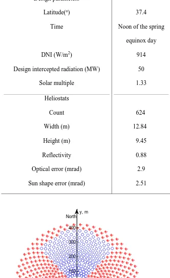
A case study is conducted to illustrate the feasibility of the present concept. The heliostat field is
designed to meet the requirement of a 11MW solar thermal power plant. The main parameters used
in the optimization analysis are listed in Table 1.
7
Design parameters
Latitude(o)
Time
DNI (W/m2)
Design intercepted radiation (MW)
Solar multiple
Heliostats
Count
Width (m)
Height (m)
Reflectivity
Optical error (mrad)
Sun shape error (mrad)
37.4
Noon of the spring
equinox day
914
50
1.33
624
12.84
9.45
0.88
2.9
2.51
-400 -300 -200 -100 0 100 200 300 400
-200 -100 0 100 200 300 400
y, m
[image:8.595.48.380.82.625.2]x, m North
8
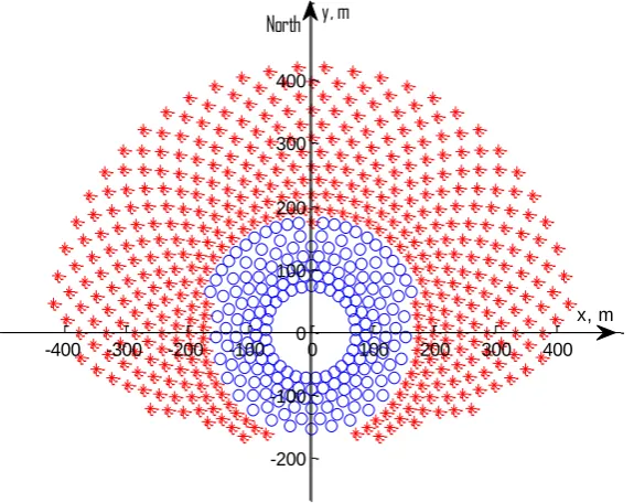
The heliostat field layout is optimized to obtain the maximum annual energy through the Campo
code [14], which searches from the densest layout and then progresses towards expanded
distributions. The resulted heliostat field layout divided into two sectors is shown in Fig. 2. The
blue sector, which has a view angle of 90ºand 182 heliostats, focuses the sunlight to the bottom
superheater. The red sector has 442 heliostats and is dedicated to the top boiler section. The total
efficiency of heliostat field obtained is 72.17%.
3 Thermal analysis of the dual-receiver
3.1 Dual-receiver geometry
To compare with a typical SPT system, the inlet feed water temperature is set to be 205ºC and the
outlet parameters of the superheat steam are 10.7MPa and 515ºC, respectively.
The top external receiver has a cylindrical shape with height of 10m and diameter of 7m. The
receiver comprises 16 parallel rising panels. The outer diameter of each tube is 26.7mm and wall
thickness is 4mm. All tubes are made of SA-192 carbon steel with a yield strength of 180MPa and
an allowable temperature of 510ºC [12]. The boiler is of a drum type with forced circulation and the
outlet steam quality is 0.1.
Ceiling-passive
Floor-passive
Entrance-passive
Wall 1-active Wall 2-active Wall 3-active
Wall 4-active
0
.5
m
7
m
10 m
0
.5
m
Top lip-passive
Bottom lip-passive
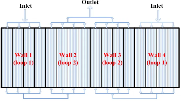
9 Wall 1
(loop 1)
Wall 2 (loop 2)
Wall 3 (loop 2)
Wall 4 (loop 1) Outlet
Inlet Inlet
[image:10.595.62.379.78.255.2](b) Fluid flow layout of the active heated walls.
Fig. 3. The bottom cavity receiver.
The bottom cavity receiver has a half octagon shape with height of 8m and radius of 5m, as
shown in Fig. 3(a). The receiver inclination is 25º and has a 7×10m rectangular aperture. Each
active heated wall has 4 panels, of which the fluid flow layout is shown in Fig. 3(b). The outer
diameter of tube is also 26.7mm with a wall thickness of 4mm. The tube material is stainless steel
SA-213TP304H, which has a yield strength of 206MPa and allowable temperature of 760oC [12].
All tubes are coated by Pyromark with an emissivity of 0.95. The cavity ceiling, floor and lip
passive insulation walls are made of ceramic fibers, whose emissivity is 0.2.
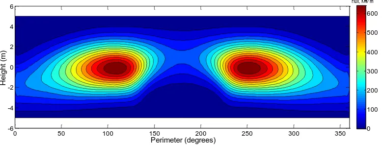
3.2 Surface heat flux distribution
The surface heat flux distribution of the present dual-receiver was obtained by the Monte-Carlo
method. A multiple aim points strategy, proposed by [12], was applied under the condition of the
maximum heat fluxes on the boiling and superheating sections below 650kW/m2 and 300kW/m2,
respectively. Fig. 4 shows the simulated heat flux distribution of the dual-receiver. It can be
10
bottom cavity receiver collected 14.19MW solar heat, while the ceiling-passive wall and
floor-passive wall obtained incident solar heat of 0.25MW and 0.04MW, respectively.
Perimeter (degrees) H e ig h t (m )
0 50 100 150 200 250 300 350
-6 -4 -2 0 2 4 6 0 100 200 300 400 500 600 Flux, KW/m2
(a) Boiling receiver (Perimeter of 180 º is the north direction).
Width (m) H e ig h t (m )
-6 -4 -2 0 2 4 6
-4 -3 -2 -1 0 1 2 3 4 0 50 100 150 200 250
Flux, KW/m2
[image:11.595.63.452.131.279.2](b) Superheating receiver.
Fig. 4. Surface heat flux distribution for the dual-receiver at the noon of the spring equinox day.
3.3 Heat transfer analysis of the dual-receiver
3.3.1 Pressure drop
Considering the arrangement of the case study, the friction and gravity pressure drop dominates
and the acceleration pressure drop can be neglected. The pressure drops of one-phase and two-phase
flow were respectively calculated by [15],
11
2 2
2 (1 )
( (1 ) )
2
sl
sv sl sl
i
u x
dp
a a g f
dz d (2)
where f is the friction factor, determined by the Moody’s correlation [12], 2 1 20 /Xtt1/Xtt2,
and Xtt is the Martinelli parameter.
3.3.2 Heat transfer coefficient
For single phase water only or vapor only flowing in the tube, the heat transfer coefficient can be
obtained by the Dittus-Boelter’s equation [16],
0.8 0.4
0.023 Re Pr /
f f f f i
h d
(3)
Totally three subcooled boiling regimes can be distinguished in the heated panels of the top
cylinder receiver, namely partial flow boiling, fully developed boiling and significant void flow.
The onset point of the subcooled boiling was determined by the Bergles’s equation [16],
5 0.0234 0.463(10 ) 5 1.156 0.556( ) 1082(10 ) P w sat q T T P (4)
and the corresponding heat transfer coefficient of partial flow boiling was obtained by Moles and
Shaw’s formula [17],
0.5
0.67 * 0.03 0.45
78.5 ( / ) Pr
foc f sv sl f
h h Bo Ja
(5)
where Bo is boiling number,
lh
q Bo
GH
, and Ja* is the Jakob number, * ( sat f)
lh
c T T
Ja
H
.
Shah [17] obtained the onset superheat of the fully developed boiling as,
2 sat f w sat T T T T (6)
and the heat transfer coefficient for fully developed boiling and significant void flow, hfoc, can be
12
* 1
(1/ ( ) / )
foc f
h h f Bo x x
(7)
where
0.5 5
0.5 5
230 , 3 10
( )
1 46 , 3 10
Bo Bo f Bo Bo Bo
, x T csub f /Hlh and
*
/ ( )
f f lh
x qc h H .
For the saturated boiling regime, Chen’s formula [16] including the contributions from both
macroscopic and microcosmic convection heat transfer was used ,
, ,
foc foc mac foc mic
h h h
(8)
0.8 0.4
, 0.023 Re Pr /
foc mac sl sl sl i
h K d
(9)
0.79 0.45 0.49
0.24 0.75
, 0.00122( 0.5 0.29 0.24 0.24)
sl sl sl
foc mic gr gr
sl lh sv
c
h T P S
H (10)
where K and S are empirical values, and is the surface tension.
3.3.3 Heat loss
The heat loss of the dual-receiver includes three parts, including that of reflective loss, radiative
loss and convective loss. The conductive loss is very small and can be neglected in the analysis.
The heat loss for the top cylinder receiver for boiling can be obtained by the known tube wall
temperature as follows [18],
, (1 ) ,
B ref B B in
Q A q
(11)
4 4
, ( , )
B rad B B w
Q A T T (12)
, , ( , )
B conv B B nc B w
Q A h T T
(13)
in which, hB,nc can be acquired from B nc, B nc,
h l
Nu
13
,
1/3 0.14
, ( )0.098 ( )
2 B w B nc T Nu Gr T
(14)
in which, is the Boltzmann constant and
3 ,
2
( B w )
g T T l
Gr
is the Grashof number.
Regarding the bottom receiver for superheating, eight sub-surfaces are considered including the
aperture. The radiative heat loss is obtained by [19],
8 4
, , , , , , ,
1
(1 )
S rad k k S w k k k j S rad j
j
J T F J
(k1, 2, 8)(15)
7
, , , , ,8
1
S rad S k S rad k k
k
Q A J F
(16)
where JS,rad,k is the effective radiation leaving a surface including reflected fraction of the irradiation
and direct emission. Fk,j is the view factor between any two surfaces and evaluated by Nicolas
Lauzier [20].
The reflective heat loss can be calculated similar to the radiative heat loss,
8
, , , , , , ,
1
(1 ) (1 )
S ref k k S in k k k j S ref j
j
J q F J
(k1, 2, 8)(17)
7
, , , , ,8
1
S ref S k S ref k k
k
Q A J F
(18)
where JS,ref,k is the effective reflection leaving a surface including re-reflected fraction and direct
reflection for the incident solar energy.
The natural convective loss was based on the Siebers and Kraabel equation [18],
, , , , ( , , )
S conv k S k S nc S w k
14
0.426 1 3 0.63
, , ,
2 1
0.81( ) ( )( )
S nc S w average
A A
h T T
A A
(20)
where TS,w,average is the average temperature of the active and passive heated surfaces, A1 is the total
interior cavity surface area, A2 is interior cavity surface area below the horizontal plane, which cuts
through the cavity at the top lip of the aperture, and A3 is the difference between A1 and the area of
the bottom lip.
4 Results and discussions
4.1 Performance of the dual-receiver at the design conditions
The performance of the proposed dual-receiver was examined at the noon of the spring equinox
day. For the top boiling receiver, the mass flow rate in each parallel rising panel was varied to
ensure that the pressure drop through all panels was equal. Heat flux distribution was east-west
symmetric, as shown in Fig. 4. For the east half of the boiling panels, from south to north, the
average heat flux was 73.8kW/m2, 108.4kW/m2, 165.4kW/m2, 234.1kW/m2, 279.3kW/m2,
247.4kW/m2, 119.6kW/m2 and 62.7kW/m2, respectively. The corresponding mass flow rates to
achieve the same pressure drop through all panels were acquired as 8.7kg/s, 11.1kg/s, 12.3kg/s,
11.9kg/s, 11.4kg/s, 11.8kg/s, 11.5kg/s and 7.6kg/s by Eq. (1)–(2). And the inlet boiler flow
velocity of the panels varied from 0.8m/s to 3.6m/s
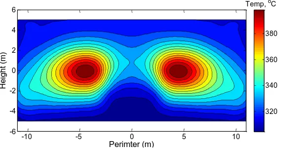
The surface temperature of the panel can be obtained by iteration. Firstly, the solar heat
absorbing efficiency was assumed an initial value. The surface temperature of the panel was then
obtained by considering the forced convection of the inner tube and the heat conductivity of the
tube wall. Accordingly, new efficiency of each panel could be reached by calculating heat loss with
the surface temperature distribution obtained. The iteration was terminated till a preset convergence
criterion was reached, under which, the surface temperature distribution of the panel was acquired.
15
The highest surface temperature was 398ºC, which was lower than the allowable temperature of
510ºC for SA-192 carbon steel. In the present design, the reflective, radiative and convective heat
losses were calculated as 1774.1kW, 1554.1kW and 872.8kW, respectively, achieving a thermal
efficiency of 88.16% for the top boiling receiver.
Perimter (m)
H
e
ig
h
t
(m
)
-10 -5 0 5 10
-6 -4 -2 0 2 4 6
[image:16.595.63.349.183.334.2]320 340 360 380 Temp, oC
Fig. 5. Panel surface temperature distribution of the top boiling receiver (Perimeter of 0m is the
north direction).
For the bottom superheating receiver, both east half and west half panels were split into two
serial loops, as shown in Fig. 3. The mass flow rate of steam from the drum was 17.3kg/s, and was
uniformly distributed at the inlets of the first loop. The outlets were mixed and fed into the second
loop. The streamline velocity of superheat steam varied from 3.7 to 7m/s due to the change of steam
density.
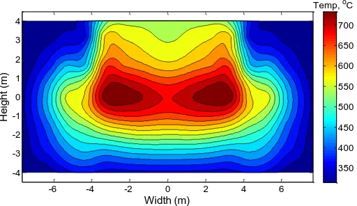
Similar iteration was executed to obtain the panel surface temperature distribution of the bottom
cavity receiver, as shown in Fig. 6. The highest temperature was 733ºC, which also below the
allowable temperature of 760ºC for SA-123TP203H. The total heat loss included reflective loss of
434.5kW, radiative loss of 1378.8kW and natural convective loss of 701kW, achieving a thermal
16
Width (m)
H
e
ig
h
t
(m
)
-6 -4 -2 0 2 4 6
-4 -3 -2 -1 0 1 2 3 4
400 500 600 700
350 450 550 650
[image:17.595.64.320.74.222.2]Temp, oC
Fig. 6. Panels surface temperature distribution of the bottom superheating receiver.
4.2 Comparison of the present dual-receiver with a two-cylinder design under design conditions
To illustrate the advantages of the present new concept, a comparative study was conducted with
a two-external cylindrical setup [10], as shown in Fig. 7. Both setups were based on a surrounding
field and had two receivers, aiming for the separation of the boiling and superheating sections. Both
setups were compared under the same conditions in terms as follows.
design latitude and time;
heliostat parameter, count and location;
active heated surface area;
receiver center height;
inlet and outlet water/steam parameters.
The heliostat field layout of the two-external cylindrical setup is shown in Fig.8. The blue sector
had 196 heliostats, which all focused sunlight onto the superheater, while the red sector for the
boiler having 428 heliostats. The boiling receiver had a cylindrical shape with the height of 10m
and the diameter of 7m. The superheating receiver was also cylindrical whose height and diameter
17
Fig. 7. Schematic diagram of the two-cylinder setup with surrounding heliostat field.
-400 -300 -200 -100 0 100 200 300 400
-200 -100 0 100 200 300 400
x, m y, m
North
Fig. 8. Heliostat field layout of the two-cylinder setup.
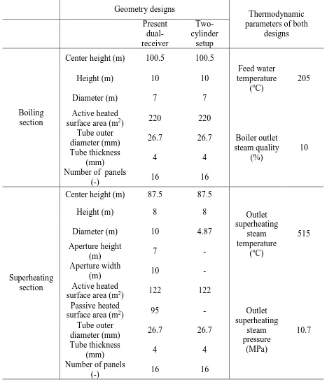
For comparison, table 2 summarizes the geometry and thermodynamic parameters both of the
present proposed dual-receiver and the two-cylinder setup.
Table 2. Geometry designs and thermodynamic parameters of the present dual-receiver and the
[image:18.595.62.350.345.573.2]18
Geometry designs
Thermodynamic parameters of both
designs Present dual-receiver Two- cylinder setup Boiling section
Center height (m) 100.5 100.5
Feed water temperature
(oC)
205
Height (m) 10 10
Diameter (m) 7 7
Active heated
surface area (m2) 220 220
Boiler outlet steam quality
(%)
10 Tube outer
diameter (mm) 26.7 26.7
Tube thickness
(mm) 4 4
Number of panels
(-) 16 16
Superheating section
Center height (m) 87.5 87.5
Outlet superheating
steam temperature
(oC)
515
Height (m) 8 8
Diameter (m) 10 4.87
Aperture height
(m) 7 -
Aperture width
(m) 10 -
Active heated
surface area (m2) 122 122
Outlet superheating steam pressure (MPa) 10.7 Passive heated
surface area (m2) 95 -
Tube outer
diameter (mm) 26.7 26.7
Tube thickness
(mm) 4 4
Number of panels
[image:19.595.69.536.72.621.2](-) 16 16
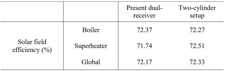
Table 3 gives solar field efficiency and thermal efficiency at the design conditions for the present
proposed dual-receiver and the two-cylinder setup. To conduct a realistic comparisons, the inlet and
outlet water/steam parameters of both receivers were set as the same as the Solar One plant with a
19
applied, the solar field efficiencies and the boiling receiver thermal efficiencies of both receivers
were approximately similar.
However, the thermal efficiency of the bottom superheating receiver increased by 9.37% when
using the cavity receiver instead of the external receiver, due to the reduction of heat loss. For the
cavity receiver, both radiative and reflective heat loss occurred inside the receiver aperture, which
was much smaller than that of the cylindrical design. The convective loss occurred at the inner
surfaces including both the active and passive parts, which had an approximately 44% heat transfer
area larger than the cylindrical design. However, air temperature inside the cavity was much higher
than the outside temperature, which could effectively reduce the convective heat loss. Based on the
temperature difference between the wall and external air, the equivalent convective heat transfer
coefficient of the cavity inner surface can be acquired from Eq. (14) and Eq. (20), which was about
8W/m2·K for the cavity receiver and 14W/m2·K for the external receiver. The difference can reduce
the convective loss of the cavity receiver in further compared to that of cylindrical case. As shown
in table 3, it can be found that much smaller heat loss was achieved for the present new design. The
calculated global receiver thermal efficiency of the present proposed dual-receiver was 3.2% higher
than that of the original two-cylinder setup.
Table 3. The solar field and thermal efficiency under the design conditions for the present
dual-receiver and the two-cylinder setup.
Present dual- receiver
Two-cylinder setup
Solar field efficiency (%)
Boiler 72.37 72.27
Superheater 71.74 72.51
[image:20.595.50.447.620.745.2]20
Receiver efficiency (%)
Boiler 88.16 87.98
Superheater 82.64 73.27
Global 86.55 83.35
Superheater heat loss efficiency (%)
Convective loss 4.84 5.4
Radiative loss 9.52 16.32
[image:21.595.50.456.67.243.2]Reflective loss 3 5
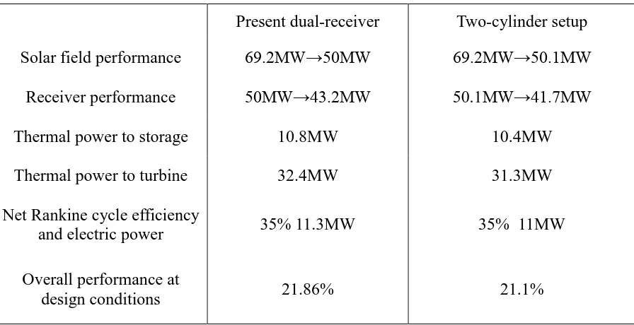
Table 4 compares the overall performance of the two dual-receiver designs. Assuming the same
generator efficiency, the total solar plant efficiency was improved by 0.76% for the present
proposed dual-receiver, correspondingly producing extra 0.3MW electrical power.
Table 4. Overall performance at design conditions for the present dual-receiver and the
two-cylinder setup.
Present dual-receiver Two-cylinder setup
Solar field performance 69.2MW 50MW 69.2MW 50.1MW
Receiver performance 50MW 43.2MW 50.1MW 41.7MW
Thermal power to storage 10.8MW 10.4MW
Thermal power to turbine 32.4MW 31.3MW
Net Rankine cycle efficiency
and electric power 35% 11.3MW 35% 11MW
Overall performance at
design conditions 21.86% 21.1%
[image:21.595.75.523.432.662.2]21
To examine the performance of the new design under off-design conditions, different solar time
of the spring equinox day was considered, which changed the solar flux map on the receiver and
correspondently the inlet mass flow rate of HTF.
Comparing Fig. 9 and Fig. 10, which show respectively the incident surface flux distribution for
the present dual-receiver at 8:00am and 10:00am of the spring equinox day, it can be found that the
solar flux peaks of both boiling and superheating receivers moved from east to west when time
changes from 8:00am to 12:00am, due to the solar azimuth moves. Different to the symmetrical
case as in the noon as shown in Fig. 4, there was an unbalalnced distribution of heat fluxes at the
off-design times shown in Fig. 9 and 10. For instance, the maximum heat flux of left side receiver
was about two times as that of rght side, as shown in Fig. 9(a). Hence, to accommodate the
requirement of the same exit quality from the boiler, the mass flow rate should be reduced
corresponding to the reduction in the incident surface heat flux, so did the exit steam temperature
from the superheater.
Perimeter (degrees) H e ig h t (m )
0 50 100 150 200 250 300 350
-6 -4 -2 0 2 4 6 0 100 200 300 400
Flux, KW/m2
(a) Boiling receiver (Perimeter at 180o is north direction).
Width (m) H e ig h t (m )
-6 -4 -2 0 2 4 6
-4 -3 -2 -1 0 1 2 3 4 0 40 80 120 160
22
[image:23.595.138.458.130.251.2](b) Superheating receiver.
Fig. 9. Surface heat flux distribution for the dual-receiver at 8:00am of the spring equinox day.
Perimeter (degrees) H e ig h t (m )
0 50 100 150 200 250 300 350
-6 -4 -2 0 2 4 6 0 100 200 300 400 500 600 Flux, KW/m2
(a) Boiling receiver (Perimeter at 180o is north direction).
Width (m) H e ig h t (m )
-6 -4 -2 0 2 4 6
-4 -3 -2 -1 0 1 2 3 4 0 50 100 150 200 250
Flux, KW/m2
[image:23.595.144.439.157.469.2](b) Superheating receiver.
Fig. 10. Surface heat flux distribution for the dual-receiver at 10:00am of the spring equinox day.
Table 5 lists the heat losses and the performance of each parts of the present dual-receiver at
8:00am, 10:00am and 12:00am of the spring equinox day. Due to the decrease in the surface
temperature in the morning, both radiation and convective heat losses were reduced. However, the
percentages of these heat losses were increased for both boiling and superheating sections, due to
the reduction in the total heat input, which was decided by the DNI and solar field efficiency.
Comparing to the boiling section, the radiative heat loss became dominant in the superheating
section, which varied from 9.5% to 13.2% at different times, due to its strong dependence on the
[image:23.595.170.427.295.463.2]23
decided by the saturation temperature of the fluid, which only varied slightly at different off-design
points. As a contrast, the increase of the wall temperature in the superheating section can be
200-300K higher than that of the boiling section, which is therefore responsible for the increased heat
loss from the radiation.
Similar cases were found at other comparative time points, i.e. 12:00am of the summer solstice
day and 9:00am of the winter solstice day, which were chosen to illustrate the thermal efficiency
performances of the present new design. It was obtained that the thermal efficiency varied from
80% to 87%. It should be noted that when 9:00am of the winter solstice day, outlet steam
temperature was 496oC, which was 19oC lower than the design value of the outlet steam
temperature. Such a lower outlet steam temperature would lead to lower Rankine cycle efficiency
and higher humidity on the last stages of the steam turbine. As typical allowable outlet steam
temperature deviation is from -10 to 5oC [22], the inlet mass flow rate or the number of heliostats
corresponding to boiling and superheating receiver shall be adjusted to obtain appropriate outlet
steam temperature under such conditions .
Table 5. The present dual-receiver performances at different time points.
Time
spring equinox 12:00am
spring equinox 10:00am
spring equinox
8:00am
summer solstice 12:00 am
winter solstice 9:00am
DNI (W/m2) 914 869 685 937 573
Solar field efficiency (%) 72.17 69.69 60.85 71.65 58.39
Evaporator specific mass
flow rate (kg/m2·s) 540-880 449-807 242-625 566-887 164-538
Superheater outlet
flow rate (kg/s) 17.3 15.7 10.4 17.6 8.1
Superheater outlet
steam temperature (oC) 515 515 510 515 496
Boiling receiver
[image:24.595.69.530.523.788.2]24
Convective loss (%) 2.46 2.67 3.8 2.42 4.67
Radiative loss (%) 4.38 4.72 6.62 4.31 8.05
Reflective loss (%) 5 5 5 5 5
Superheater receiver
thermal efficiency (%) 82.64 81.78 77.04 82.82 73.28
Convective loss (%) 4.84 5.12 6.79 4.78 8.33
Radiative loss (%) 9.52 10.1 13.17 9.4 15.39
Reflective loss (%) 3 3 3 3 3
Total Receiver thermal
efficiency(%) 86.55 85.89 82.34 86.66% 79.78
4.4 Influence of tube diameter
For a consistent comparison, the influence of tube diameter on the system performance was
investigated under the same solar flux map, geometry of receiver, inlet water/steam parameters,
inlet total mass flow rate and tube thickness as in section 3.
For the boiling receiver, the mass flow rate in each parallel rising panel was different to ensure
that the pressure drop through all panels was equal. When the tube outer diameter was reduced, the
mass flow rate was found to increase for the panels with relatively lower surface heat fluxes, but
decreased for panels with higher surface heat fluxes. This can be attributed to the different pressure
drop components. For low heat flux panels, the gravitational pressure drop was dominant, whereas
for higher heat flux panels, the frictional component was the major contribution. Consequently, the
higher heat flux panels were prone to the overheating problem due to the reduction in the mass flow
rate, which should be considered in practice. One potential solution would be the proper use of
throttle orifices, which should be located at the panel entrance with adjustable orifice diameters
25
were set as 115, 94, 60, 25, 0, 17, 86 and 123, respectively from south to north, and the local
resistance coefficients remained the same for different tube diameters.
Table 6 shows the influence of tube outer diameter on the boiling receiver. When the tube outer
diameter was reduced from 26mm to 16mm, the flow velocity was increased under the same mass
flow rate, resulting in the increase of the heat transfer coefficient. The thermal efficiency of the
boiling receiver, excluding the parasitic loss, was increased by only ~0.05%. This was, however,
compromised by a sharp increase in the pressure drop, i.e., from 85kPa to 772kPa. The overall
receiver thermal efficiency was reduced from 87.86% to 85.53% when the increased pumping
power was considered. Clearly it is not always beneficial to decrease the tube size, which shall be
[image:26.595.68.531.415.645.2]considered collectively for the boiler section.
Table 6. Influence of tube outer diameter for boiling receiver.
Tube outer diameter
(mm)
Boiling receiver thermal efficiency excluding parasitic
loss (%)
Flow velocity
(m/s)
Heat transfer coefficient
(kW/m2·k)
Pressure drop (kPa)
Boiling receiver thermal efficiency
including parasitic loss(%)
26 88.16 0.8-4.3 7.3-46.7 85 87.86
24 88.16 0.9-4.8 8.9-48.8 102 87.81
22 88.16 1.2-5.7 11.4-53.7 136 87.7
20 88.16 1.7-7 14.9-54.8 201 87.49
18 88.17 2.3-9 17.9-59.9 342 87.02
16 88.21 3.5-13 25.3-70.9 772 85.53
For the superheating receiver, the influence of tube outer diameter is shown in Table 7. When the
tube outer diameter was reduced from 26mm to 14mm, the receiver thermal efficiency was
improved by ~3%, much higher than the boiler section. This is related to the relative importance of
26
and further improve the flow boiling heat transfer coefficient would not change the heat loss.
However for the superheating section, the major heat resistance came from the internal convection.
A size reduction would reduce the heat loss saliently due to the increased in heat transfer coefficient
inside the pipe. However as previously, the pressure drop was also raised significantly from 8kPa to
585kPa. A parametric study of the size effect suggested that the thermal efficiency of the
superheating receiver, including parasitic loss, reached its maximum performance at an outer
[image:27.595.61.532.347.614.2]diameter of 18mm.
Table 7. Influence of tube outer diameter for superheating receiver.
Tube outer diameter
(mm)
Superheating receiver thermal
efficiency excluding parasitic
(%)
Flow velocity
(m/s)
Heat transfer coefficient
(kW/m2·k)
Pressure drop (kPa)
Superheating receiver thermal
efficiency including parasitic loss (%)
26 82.83 3.9-7.4 1-2.4 8 82.68
24 83.36 4.6-8.6 1.5-2.8 13 83.14
22 83.85 5.4-10.2 1.8-3.3 21 83.51
20 84.39 6.7-12.8 2.2-4 39 83.82
18 84.85 8.6-16.5 2.8-5.1 76 83.83
16 85.36 12-23.4 3.8-7 186 83.05
14 85.83 18.6-37.4 5.7-10.4 585 78.17
5 Conclusions
A novel dual-receiver with a surrounding solar field was proposed to improve the efficiency of
solar power tower (SPT). The new concept comprised an external receiver and a cavity receiver,
respectively designated for the boiling section and superheating section, providing a convenient yet
27
(1) The new design of 11MW solar power plant achieved an overall thermal efficiency of 86.55%
under design conditions, generating 17.3kg/s superheated steam at 515oC and 10.7MPa.
(2) A comparative study of 11MW solar power plant was conducted based on the new design and
a two-external cylindrical setup. The present design improved the thermal efficiency of the
superheating section by about 9.37%, and the global thermal efficiency of the SPT by 3.2%.
(3) The plant performance was affected significantly by the incident solar fluxes at different time
of a day, and even exceeded the range of allowable outlet steam temperature, which required a
proper control of the inlet mass flow rate or the heliostats focus.
(4) It is not always beneficial to decrease the tube size for the benefit of heat transfer
enhancement and an optimized tube diameter of ~18 mm for the superheating receiver was
proposed based on the collective consideration of the heat transfer effect and pumping power
requirement.
Appendix. Model validation
Monte-Carlo method is validated in this section. By using original heliostat field layout of PS10
power plant and receiver data, net power and flux peak of PS10 receiver at the noon of the spring
equinox day were obtained by Monte-Carlo method. Table A1 gives the comparison of PS10 data
[13] and our Monte-Carlo method simulated results. It can be seen that Monte-Carlo method is very
close to literature data, and the method was then used in this study to configruate the heliostat fields.
Table A1. Comparison of net power and flux peak between data of PS10 and the present
Monte-Carlo results at noon of the spring equinox day.
PS10 literature data Monte-Carlo
Net power (MW) 51.9 51.5
28
Acknowledgment
The financial supports for this research project from the National Natural Science Foundation of
China (No.U1361108), the national “973 Program” of China (No. 2015CB251503) and the 111
Project (B12034) are gratefully acknowledged.
References
[1] O. Behar, A. Khellaf, K. Mohammedi, A review of studies on central receiver solar thermal
power plants, Renewable and Sustainable Energy Reviews, 23 (2013) 12-39.
[2] A.L. Avila-Marin, J. Fernandez-Reche, F.M. Tellez, Evaluation of the potential of central
receiver solar power plants: Configuration, optimization and trends, Applied Energy, 112 (2013)
274-288.
[3] L. Yebra, M. Berenguel, S. Dormido, M. Romero, Modelling and simulation of central receiver
solar thermal power plants, in: Decision and Control, 2005 and 2005 European Control
Conference. CDC-ECC'05. 44th IEEE Conference on, IEEE, 2005, pp. 7410-7415.
[4] R. Osuna, V. Fernandez, M. Romero, M.J. Marcos, PS10, A 10 MW Solar Tower Power Plant
for Southern Spain, in, 2001.
[5] J.E. Pacheco, eSolar’s Modular Concentrating Solar Power Tower Plant and Construction of the
Sierra Solar Generating Station, in: ASME 2009 3rd International Conference on Energy
Sustainability collocated with the Heat Transfer and InterPACK09 Conferences, American
Society of Mechanical Engineers, 2009, pp. 701-705.
[6] E. Xu, Q. Yu, Z. Wang, C. Yang, Modeling and simulation of 1 MW DAHAN solar thermal
29
[7] T.M. Pavlović, I.S. Radonjić, D.D. Milosavljević, L.S. Pantić, A review of concentrating solar
power plants in the world and their potential use in Serbia, Renewable and Sustainable Energy
Reviews, 16 (2012) 3891-3902.
[8] L. Crespo, F. Ramos, F. Martínez, Questions and answers on solar central receiver plant design
by NSPOC, in: 17th annual SolarPACES symposium, 2011.
[9] J. Sanz-Bermejo, V. Gallardo-Natividad, J. Gonzalez-Aguilar, M. Romero, Comparative System
Performance Analysis of Direct Steam Generation Central Receiver Solar Thermal Power
Plants in Megawatt Range, Journal of Solar Energy Engineering, 136 (2014) 011028.
[10] Y. Gilon, I. Kroizer, G. Kroyzer, Method and control system for operating a solar power tower
system, U.S. Patent No. 8,001,960, (2011).
[11] M.S. Gonzalez, R.O. Gonzalez-Aguilar, V.F. Quero, R.N. Gilaberte, Solar concentration plant
for the production of superheated steam, U.S. Patent No. 8,365,720, (2013).
[12] R. Ben-Zvi, M. Epstein, A. Segal, Simulation of an integrated steam generator for solar tower,
Solar Energy, 86 (2012) 578-592.
[13] V.D. Fernández, PS10: a 11.0-MWe Solar Tower Power Plant with Saturated Steam Receiver,
(2005).
<http://www.upcomillas.es/catedras/crm/report05/Comunicaciones/Mesa%20IV/D%20Valerio
%20Fern%C3%A1ndez%20-%20Solucar%202.pdf>.
[14] F.J. Collado, J. Guallar, A review of optimized design layouts for solar power tower plants
with campo code, Renewable and Sustainable Energy Reviews, 20 (2013) 142-154.
[15] J. Zambrana, T.J. Leo, P. Perez-del-Notario, Vertical tube length calculation based on available
heat transfer coefficient expressions for the subcooled flow boiling region, Applied Thermal
Engineering, 28 (2008) 499-513.
[16] L. Zhonghu, Two-phase of steam and water and heat transfer, Xian Jiaotong University Press,
30
[17] V. Prodanovic, D. Fraser, M. Salcudean, On the transition from partial to fully developed
subcooled flow boiling, International journal of heat and mass transfer, 45 (2002) 4727-4738.
[18] D.L. Siebers, J.S. Kraabel, Estimating convective energy losses from solar central receivers, in,
Sandia National Labs., Livermore, CA (USA), 1984.
[19] M. Montiel Gonzalez, J. Hinojosa Palafox, C.A. Estrada, Numerical study of heat transfer by
natural convection and surface thermal radiation in an open cavity receiver, Solar Energy, 86
(2012) 1118-1128.
[20] N. Lauzier, View Factors with GUI, (2004).
<http://www.mathworks.com/matlabcentral/fileexchange/5664-view-factors>.
[21] L. Jianming, Solar thermal power generation technology, Chemical Industry Press, 2012.
31
Table captions
Table 1. Main parameters used in the optical analysis.
Table 2. Geometry designs and thermodynamic parameters of the present dual-receiver and the
two-cylinder setup.
Table 3. The solar field and thermal efficiency under the design conditions for the present
dual-receiver and the two-cylinder setup.
Table 4. Overall performance at design conditions for the present dual-receiver and the
two-cylinder setup.
Table 5. The present dual-receiver performances at different time points.
Table 6. Influence of tube outer diameter for boiling receiver.
Table 7. Influence of tube outer diameter for superheating receiver.
Table A1. Comparison of net power and flux peak between data of PS10 and the present
Monte-Carlo results at noon of the spring equinox day.
Figure captions
Fig. 1. Schematic diagram of the proposed dual-receiver with solar field.
Fig. 2. Heliostat field layout of the proposed dual-receiver.
Fig. 3. The bottom cavity receiver. (a) The cavity receiver geometry. (b) Fluid flow layout of the
active heated walls.
Fig. 4. Surface heat flux distribution for the dual-receiver at the noon of the spring equinox day. (a)
Boiling receiver (Perimeter of180º is north direction). (b) Superheating receiver.
Fig. 5. Panel surface temperature distribution of the top boiling receiver (Perimeter of 0m is the
north direction).
Fig. 6. Panels surface temperature distribution of the bottom superheating receiver.
Fig. 7. Schematic diagram of the two-cylinder setup with surrounding heliostat field.
32
Fig. 9. Surface heat flux distribution for the dual-receiver at 8:00am of the spring equinox day. (a)
Boiling receiver (Perimeter at 180o is north direction). (b) Superheating receiver.
Fig. 10. Surface heat flux distribution for the dual-receiver at 10:00am of the spring equinox day. (a)