Commission of the European Communities
industrial o sses
building
and civil
e ineering
Testing and classification
of the resistance to fire
Commission of the European Communities
Testing and classification
of the resistance to fire
of structural building components
Report submitted by:
J.
Dekker,1 M. Klingelh0fer,2 P. Vandevelde 31 lnstituut TNO voor Bouwmaterialen en Bouwconstructies Rijswijk, Nederland
(TNO Institute for Building Materials and Construction) (The Netherlands)
2 Staatliches Materialprufungsamt Nordrhein-Westfalen Dortmund, BR Deutschland
(North Rhine-Westphalia State Materials Testing Office) (Federal Republic of Germany)
3 Laboratorium voor Aanwending der Brandstoffen en Warmte-Overdracht
Gent, Belgie
1984
(Laboratory for Fuel Applications and Heat Transfer) (Belgium)
Directorate-General
Internal Market and Industrial Affairs
Published by the
COMMISSION OF THE EUROPEAN COMMUNITIES Directorate-General
Information Market and Innovation BAtiment Jean Monnet
LUXEMBOURG
LEGAL NOTICE
Neither the Commission of the European Communities nor any person acting on behalf of the Commission is responsible for the use which might be made of the
following information
This publication is also available in the following languages: DE ISBN 92-825-4781-7
FR ISBN 92-825-4783-3
Cataloguing data can be found at the end of this publication
PREFACE
In recent years, the harmonization measures undertaken in the building and civil engineering sector have included work on the fire resistance of structural elements.
These activities led to the preparation in September 1977 of a preliminary draft Directive relating to the "classification on the basis of test results of the fire resistance of structural elements" which is well known among the circles concerned as "document 1202".
"Document 1202" is an internal Commission working document based on document ISO D.I.S. 834 and was prepared by joint working parties made up of experts from the relevant national ministries and representatives of the
approved testing laboratories and the industry.
lmplementation of the provisions of such a document in the form of a directive implies a reciprocal recognition of test results and classificat-ions and raises the problem of the comparability of results obtained when using facilities (test furnaces) which exhibit different structural and
operational features. In an effort to find a solution to the problems posed
by attempts to establish this comparability, a study of the facilities available in approved Community testing laboratories was initiated.
This investigation was carried out in two stages.
During the first, covering the period from January 1979 to
December 1980, an agreement was concluded with the three following experts:
D. VANDEVELDE
M. KINGELHOFFER
J. DEKKER
(RUG)
(MPAl
<TNOl
for the preparation of a questionnaire to be sent to the approved
laboratories.
-Ill-On the basis of this questionnaire, an enquiry involving Laboratory Visits was conducted in order to :
draw up a catalogue of the characteristics of existing installations and of the resources available to them, particularly as regards the measurements performed;
gain knowledge of the procedure employed in fire-resistance tests, with particular reference to the conditions under which test
elements are assembled and to the contents of test reports;
compare the procedures employed with the provisions Laid down in document 1202.
During the second phase of the investigation, covering the period from January 1981 to March 1983, the three specialists were responsible for :
analyzing the results of the enquiry conducted during the first phase and suggesting changes and areas requiring more detailed study
with a view to achieving an optimum degree of harmonization;
amending and supplementing document 1202 on the basis of the above-mentioned activities with a view to rendering it more relevant from the operational standpoint and to reducing differences of interpret-ation within its field of applicinterpret-ation.
The results of these activities are the subject of this report,
which is in two parts
Part I
Part II
Examination of the equipment used in testing fire resistance in approved Community Laboratories.
Method of testing and classifying the fire resistance
of structural elements.
At each stage of its progress, the study conducted by the three
consist-ing of representatives of the Community Laboratories which have been approved for the testing and classification of structural elements. This
group, the composition of which is shown in the Annex to this preface met for the Last time on 19- 21 April 1982 prior to the finalization of this
report.
This meeting produced a Large measure of agreement among the partic-ipants as regards the contents of the report. Some of them even undertook to ensure that full recognition was given to the test reports and, conseq-uently, to the classifications of structural elements based, Like the corresponding tests, on the provisions contained in Part II of this report.
At the present juncture, the Commission believes that even though this undertaking to promote voluntary harmonization is not unanimous, it is extremely important and regards it as an encouragement to continuing efforts to bring current harmonization activities to a successful conclusion.
In the field in question, these efforts will relate, in partdcular, to installations and methods of calculation and extrapolation, but will also involve an expansion of activities to cover other elements and, lastly, the promotion of sustained and continuing cooperation between the approved Laboratories.
-V-Annex to the preface
Attendance List for the meeting of representatives of approved Laboratories,
held in Brussels on 19- 21 April 1982
Germany (Federal Republic of)
C.
MEYER - OTTENSKLINGELHOFFER
WESTHOFF STANKE H. HAFNER
Belgium
P. VANDEVELDE BERTRAND S. MAEKELBERG
Denmark
E. DAN0 N. ANDERSEN
France
LE DUFF
CAVELl US
.lli.!L
S. BRUSCHETTA
Net her Lands
J. DEKKER
T.V. BRAUNSCHWEIG M.P.A. DORTMUND
M.P.A. DORTMUND B.A.M. BERLIN F.M.P.A. STUTTGART
R.U.G. GAND
Universite d'Etat de Liege
Ministere de L'Interieur
Dantest Copenhague Dantest Copenhague
C.S.T.B. -Paris
c.T.I.C.M.- Maisiere-Lez-Metz
Centro Studi Antiscendi - Roma
I.B.B.C. - T.N.O. - Delft
-VII-United Kin!jdom
H.L. MALt-KlTRA F.R.S. - Borehamwood
A.G. DEAKIN Warrington Research Centre
T.V. DAY F.I.R.T.O. - Borehamwood
P.E. JACKMAN Trada
c
.J. WIGHTENAN British GypsumCONTENTS
PART I - ANALYSIS OF FIRE TEST EQUIPMENT IN E.E.C. LABORATORIES
1. Introduction
2. General experience with doc. 1202
3. Comments on the facilities in the laboratories
4. Furnaces
5. Operating conditions
5.1. Heating
5.2.
o
2-content5.3. Pressure conditions
6. Measuring devices
6.1. Temperature inside the furnace
6.2. Pressure
6.3. The temperature on non-exposed sides
6.4. Integrity measurement
6.5. Stability
7. Loading and end conditions
7.1. Loadbearing walls
7.2. Floors
7.3. Beams
7.4. Columns
8, Test load
9. Criteria and application of test results
9.1. Criteria
9.2. Extrapolation
10. Remarks on test report
11. Final conclusions
PART II - TESTING AND CLASSIFICATION OF THE RESISTANCE TO FIRE OF STRUCTURAL BUILDING COMPONENTS
Chanter
Section I - Scope
Section II - Field of application
Section III - Test equipment
-IX-3
6
8
10
15
15
16
16
17
17
17
17
18
20
21
21
27
29
31
34
36
36
36
38
52
53
55
55
3.1. Furnace
3.2. Loading equipment
3.3. Equipment for monitoring furnace operating conditions
3.4. Equipment for measuring the behaviour of the test element
Section IV - Test specimen
4.1. Construction
4.2. Number of tests 4.3. Dimensions
4.4. Mounting and end conditions 4.5. Conditioning
Section V - Test procedure
5.1. Furnace conditions 5.2. Loading
5.3. Measurements on test specimen 5.4. Other observations during the test 5.5. Duration of test
Section VI - Criteria and classification
6.1. Criteria
6.2. Classification Section VII - Test report
Chapter 2
Section I - Non-load-bearing walls and partitions
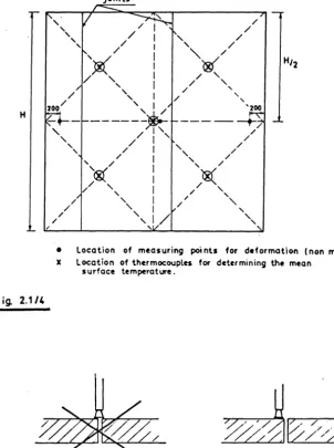
1. Design of specimen and exposure conditions 2. Furnace thermocouples
3. Measurements on test specimen
4. Number of tests 5. Performance criteria
Section II - Loadbearing walls and partitions 1. Design of specimen and exposure conditions 2. Loading
3. Furnace thermocouples
4. Measurements on test specimens
5. Number of tests 6. Performance criteria
Page 57
58
58
63
66
66
66
66
66
68
69
69
72
74
76
77
78
78
79
80
82
82
84
84
86
86
91
91
94
94
97
97
Section III - Columns
1. Design of specimen and exposure conditions
2. Leading
3. Furnace thermocouples
4. Measurements on test specimen
5. Number of tests
6. Performance criteria
Page
104
104
106
106
108
1DB
108
Section IV - Floors submitted to fire exposure at the underside 110
1. Design of specimen and exposure conditions
2. Loading
3. Furnace thermocouples
4. Measurements on test specimen
5. Number of tests
6. Performance criteria
Section V - Beams
1. Design of specimen and exposure conditions
2. Loading
3. Furnace thermocouples
4. Measurements on test specimen
5. The number of tests
6. Performance criteria
Chapter 3
Introduction
Section I - Standard report for fire resistance test on a
non-load-bearing wall or partition
1. Identification
2. Test specimen
3. Test procedure
4. Exposure conditions
5. Observations during the test
6. Duration
7. Conclusion
B. Remarks
9. Remarks
-XI-110
111
113
113
116
116
119
119
121
123
123
123
123
125
126
126
126
127
128
128
128
129
129
Section II - Standard report for fire resistance test on a load-bearing wall or partition
1. Identification
2. Test specimen
3. Test procedure
4. Exposure conditions
5. Observations during the test
6. Duration
7. Conclusion
B. Remarks
9. Remarks
Section III - Standard report for fire resistance test on a column
1. Identification
2. Test specimen
3. Test procedure
4. Exposure conditions
5. Observations during the test
6. Duration
7. Conclusion
8. Remarks
9. Remarks
Section IV - Standard report for fire resistance test on a
floor with and without a ceiling, with fire attack from the underside only
1 . Identification
2. Test specimen
3. Test procedure
4. Exposure conditions
5. Observations during the test
6. Duration
7. Conclusion
8. Remarks
130
130
130
132
132
132
133
133
134
134
135
135
135
137
137
137
138
138
139
139
140
140
140
142
142
142
143
143
144
9. Remarks 144
Section V - Standard report for fire resistance test on a
beam
1. Identification
145
Page
3. Test procedure 147
4. Exposure conditions 147
5. Observations during the test 147
6. Duration 148
7. Conclusion 148
8. Remarks 149
9. Remarks 149
-X·III-P A R T I
ANALYSIS OF FIRE TEST EQUIPMENT
1. INTRODUCTION
On request of the "Directorate General III, Internal Market
and Industrial Affairs" He three c;~.;thors undertook the task to
visit the officialy recognized Laboratories of the E.E.C., named by the national delegations in the expert group concerning resistance to fire of building elements. These were the following :
Belgium
Denmark
U.K.
R .U.G.
Laboratorium voor Aanwending der Brandstoffen en Warmte-overdracht
Ottergemse steenweg, 711 B - 9000 GENT
DANTEST
Amager Boulevard, 108
OK - 2300 COPENHAGEN
FIRTO
Melrose Avenue Borehamwood, Herts Hertfordshire WD 6 2 BL
TRADA
Stocking Lane Hughenden Valley High Wicombe
Buckinghamshire HP 14 4ND
WARRINGTON RESEARCH CENTRE Holmerfield Road
Warrington Cheshire WA1 2DS
YARSLEY TECHNICAL CENTRE Trowers Way
France
Germany
Italy
The
Netherlands
c.s.r.s.
84, Avenue Jean Jaures Champs-sur-Marne
F - 77428 Marne La Vallee Cedex 2
C.T.I.C.M.
Domaine de l'I.R.S.I.D. F - 57210 Maizieres-lez-Metz
B.A.M.
Unter den Eichen 87
D - 1000 Berlin 45
T.U. Braunschweig Beethovenstrasse, 52
D - 330G Braunschweig
M.P.A.
Marsbruchstrasse, 186
D - 460G Dortrnund
F.M.P.A.
Pfaffenwaldring, 4 D - 7000 Stuttgart
H.F. Munchen
Winzerestrasse, 45 D - 800C Munchen
Centro Studi ed Esperienzi del Ministro dell'Interno
I - 00100 Roma - Capannelle
I.B.B.C.- T.N.O. Postbus, 49 NL - 2600 AA Delft
-4-During the visits the equipment of the laboratories was looked at, and at least one test in each laboratory was observed. Additionally partic-ular questions concerning the test techniques were discussed with the
staff of the labs. In order to provide as much information as possible, in preparation of the visits a questionnaire has been prepared by the under-signed. This questionnaire included a request for test reports. The
questions were answered by the labs before the visit and the answers discussed and completed during the visits. During the exercice a second questionnaire concerning the calculation of test load was sent around.
As first result of these visits a full report, containg both the answers to the questionnaire and single reports of the visits, with all detailed information, was delivered to the sponsor. The answers to the second questionnaire here included in this report as far as available on
the day of delivery of the full report. It was found that this report included a lot of information which seemed to be important for the further
harmonization of the resistance to fire test method. Also analysis of the
test reports delivered in the laboratories seemed usefu~
The authors therefore accepted the task to analyse these voluminous docu-ments in order to prepare conclusions and guidelines for a revision of the existing document 1202.
This report therefore contains :
a) an analysis of the former report including suggestions for
modif-ications and more detailed specifmodif-ications of the test procedures;
b) a method for testing and classification of the resistance to fire
of structural building components.
Because of the increase of detailed specifications a rearrangement
of the logical order was felt to be necessary. Chapter 1 contains tte
general re~uirements of test procedure and classification, valid for all
types of elements ; Chapter 2 gives for each type of building component,
detailed instruction for the test arrangement Chapter 3 gives the
2. GENERAL EXPERIENCE WITH DOC. 1202
During the visits the authors made the experience that doc. 1202
was not well known by the Laboratories and partially not understood,
espec-ially the differences to the national standards were not sufficiently
realised and observed. So by most Laboratories, even carrying out test
following doc. 1202, the tests were done on the basis of the normal way of
working, i.e. following the national standard. Only those modifications were made where differences were realised. The results of this were Large numbers of differences in test procedure and classification in the differ-ent Labs.
The reason for this situation was found to be based on
101 A Lack of detailed specification in doc. 1202;
2°/ A Lack of accessability to the content of the existing doc. because
some information on the same subject is dispersed over the document;
3°/ A Lack of knowledge concerning the content of 1202 combined with an
underestimation of the influence of smaller details in test proced-ure on the test results.
For this reason :
the content of doc. 1202 is rearranged;
especially in Part II detailed drawings concerning the test arrang-ements are given;
tolerances for dimensions, minimum accuracy requirements and maximum intervals for measurements are specified;
end conditions and other test details are specified closely. This
means on the one hand that better harmonization will be obtained,
but on the other hand it implicates that some situations are not covered by the test, and are not tested "as in practice";
it was also felt that there was no reason to exclude protected steel members from the test procedure, as Long as the use of test results remains Limited to the element tested, and no extrapolation is made;
-6-from these discussions it appeared that extrapolation of test results is not only a problem for protected steel members but also
for other building components.
A detailed analysis of the information obtained by the questionnaire and during the visits, is given in the following chapters. Starting from
the analysis, amendments and changements to doc. 1202 are proposed. Although much attention was paid during the visits to complete the quest-ionnaires, by making the final analysis it appeared that even in the completed questionnaires some information was not very clear or even
missing. Here, either a question mark appears in the tables, or they have been completed by the authors from memory.
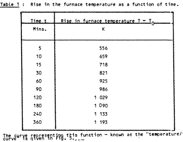
3. COMMENTS ON THE FACILITIES IN THE LABORATORIES (see table 1)
The answers to the general questions in the questionnaire give an overall idea about the situation in each laboratory.
Table 1 shows the size of the furnace halls. Their v~um~ vary
between about 300 and 15 000 m3.
It is not expected that this will influence test results unless the specimen is directly in front of a large ventilation air entrance. Most of the labs are heated but the temperatures which are likely to be encountered are between 0°C and 3ooc.
In order to avoid influence of ambient conditions on the test
results, ambient temperature in the furnace hall has to be kept approximately constant during a test. In this respect harmonization is restricted by the existing furnace halls and their ventilation possibilities.
In the majority of labs, no special conditioning room for the specimen is available.
The impression during the visits was that in most laboratories there is not enough space for storing the specimens during the conditioning time (e.g. concrete). In this light the product of the
number of tests per year multiplied by the given figures for condit-ioning time does not fit together with the space available, at least for some laboratories.
Some labs dispose on a large number of furnaces, others only on one ot two which are used for different elements.
For the multipurpose furnaces in general it will be more complicate
to fulfill the requirements for the test, especially where closer specifications are introduced in the revised document.
Those laboratories who have more than one furnace for a single purpose, probably can provide more information on the influence of furnace construction and other parameters on the test results.
It is clear that the design of the furnaces influences the test results. In order to get better reproductibility which is necessary for harmonization, it appears desirable to have detailed guidelines for the design of furnaces (preferably working drawings). Such guidelines should be published as recommendation for new furnaces
(see also chapt. 7.4).
4. FURNACES
The furnaces seen in the different labs showed large differences in respect to their dimensions, their design, their heating devices and the furnaces control.
Nine of the labs have a wall-furnace of at least 3 m x 3 m, six have only smaller furnaces.
The depth of the furnace differs between 0,36 m and 4,0 m.
The cross-section of the column furnace differs between 1,4 m diameter and 7,75 m x 5,75 m. The height is between 3,0 and 4,6 m.
The floor furnaces have a cross-section between 2 m x 4 m and 9,5 m x 4 m : their height between 0,7 and 3,1 m.
The beam furnaces have a horizontal cross section between 3,0 x 3,7 m and 4 x 11,5 m.
The height of these furnace dimension on the heat transfer to the specimen is unknown.
A second factor concerning the heat transfer is given by the klc
value of the lining. The information on those values where insufficient, most labs do not know the values for k and c.
The values for p are situated between 780 and 2 760 kg/m3.
(The question of heat transfer in furnaces is treated e.g. in the "Van Keulen" rep.ort N° TNO N° BVI 74-17, "Comparison of heat transfer in
~everal wall furnaces", althou=1h the special influence of furnace
dimensions on heat transfer is not described separately).
There seems to be no relation between density and durability of the lining.
Large furnaces have been built in order to test larger components. The existing version of doc. 1202 allows this. Especially in respect of the statical system of the components it is expected that the dimensions of the
specimen .can have great influences on the measured R/E/I values. For harmonization purpose it seems to be necessary to introduce fixed specimen dimensions in the revised doc. 1202.
-10-Table 2a -Wa 11 furnace.
---s1ze----aeptn--
-aeiisn;--
-t.Ype--;;;::-or
nr. of a x b (m) of lining tests of burners (m x m) k /m 3 untiL fuel j .e.L illillg.-
---- -~--- ----2 X 3 0,36 780 400 prop. 8 test 2,4 x3,2 1,4 850 750 gas 10 3 X 3 0,382110/850 2090/8Q_l_
150 nat.gas 100 3 X 3 1 ,3
1~~~
l~~i)
35 prop. 10 part. 3,0 x3,0 0,92 850 400 nat.gas 14 3 X 3 0,6 850 ? prop. 10 xxx) 3 X 3 0,42 2.260 240 oil 12 (u) 3,1 x3, 1 4,09 2.760 300 nat.gas 12 4,5 x3,5 1 ,5 1.000 200 oil 6 Braunschweig 4 X 3,5 1 ,5 640 150 oil 3 3 X 31 5
---5. OPERATING CONDITIONS (see also tables 2a, 2b, 2c, 2d)
5.1
!J~!!!i!:!SAs fuel natural gas, propane and oil are used. As in no Lab butane is used, it seems to be reasonable to delete it from doc. 1202.
Concerning the heat transfer with the different fuels, see the "Van Keulen" report.
The number of burners in the same type of furnace differs very strongly (for wall furnaces between 3 and 100).
The reason using a Large number of burners is to obtain a good uniformity in furnace temperature. This however was also reached in the furnaces with a small number of burners.
The figures given for the nominal capacity of the furnaces give no indication about the real combustible consumption, which is not measured
at most laboratories.
The expected relation between inner surface of a furnace, 02 content and fuel consumption is not reflected in the figures given for maximum nominal capacity. For some figures it is evident that there are mistakes. For others one can expect that the heating capacity is too Low to fulfill at the same time the requirements of 02 excess, and temperature curve for specimens with high heat Loss or Large thermal capacity.
In relation with the heat transfer the given values for the Length of the flames and the information on the Location of the burners, should be Looked at. In some furnaces the specimens are heated only by hot gasses, in
other furnaces they are subjected to direct radiation from Long flames (max. Length 2m>. For the moment being one is not in a position to
estimate the possible influence of this factor on heat transfer to specimen.
Although there is the "Van Keulen" report on heat transfer in
The aim of these study should be :
a) to show the possible influence of the single factors on test
results;
b) to examine the necessity of closer specification of the heating
conditions in a future version of doc. 1202.
Although most furnaces are equipped with automatic temperature
control, this equipment is not used and furnaces are manually controlled.
The question concerning the constancy of fuel air ratio was answered nearly in all cases yes. As it was seen during the visit in most cases the control of fuel and air were linked but as in most laboratories, neither
air and fuel consumption nor
o
2-content are measured, doubts remain withinwhat limits constancy is obtained.
5.2
Q2:£2Dl~D!In most laboratories no equipment for
o
2-measurement is available.The given figures for
o
2-content during a test on a non-combustiblemater-ial in some cases are only rough estimations (Drager tubes, which do not measure continuously).
In order to meet the requirement of doc. 1202 it is necessary to
provide
o
2-apparatuses. Experience then will show to what extent theexisting furnaces do operate at the prescribed values.
On the basis of the existing experience it can be stated that the minimum value of 2 X (see doc. 1202) can not be satisfied by specimen of combustible materials, therefore the limits of 2- 5 X where restricted to
elements of non-combustible specimen. Experience will show later if these limits can be brought closer together.
It is proposed to extend the pressure conditions for separating elements to all building components, taking into account the possible influence of convective heat transfer inside the cladding of protected load
bearing elements.
In some labs there are anomalies in pressure distribution near com-bustion gas outlets and burners. Therefore calibration tests are proposed
-16-in order to check the uniformity.
6. MEASURING DEVICES (see table 3)
Only in a few cases equipment was seen which allows to keep
cons-tant the distance between furnace thermocouples and specimen.
In order to meet this requirement special arrangements have to be
made and for the moment being it is not clear wh~ther there is a
signifi-cant influence as long as there is no contact between thermocouple and specimen. A change of doc. 1202 therefore was proposed, further measure-ments have to verify this solution.
The deflector in front of the T-shaped tube is not used in most
labs because of practical problems (deformation) and because it had no significant influence.
For the open tube it was felt that it can give different results from the T-shaped tube, therefore it is proposed that it should not be used without comparing its results with the T-shaped tube.
Besides this it seemes to be necessary to specify more clearly the
location of the pressure measuring points.
The questions concerning the time delay of pressure measurement were answered unsufficiently. The registration records with pressure pick-ups sometimes show very quick pressure changes which are not observed by
slower measuring systems.
With very quick measuring devices the differences between minimum
and maximum peaks can be more than 5 Pa.
In order to guarantee a harmonised way of working it is proposed to base furnace control on a measurement averaged over a 1 minute period.
As shown in table 3 some laboratories use only the minimum required number of thermocouples and check the hot spots with a movable thermocouple.
elements is given in Part 2.
The movable thermocouples used were different in design. A
stand-ardized movable thermocouple is defined as the design has great influence on the response.
It is felt that there is a general lack of calibration of
thermo-couples.
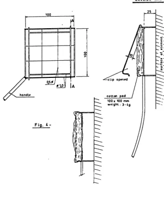
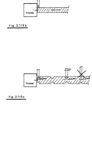
Experience during the visits showed that as well the technique of application of the cotton pad, as the evaluation and interpretation of the
results were strongly different in the labs.
In some labs the cotton pas was only applied in front of gaps in others it is also applied in front of hot surfaces (glass) or in front of flames with a duration shorter than 10 seconds. In some laboratories only flaming of the cotton pas is considered as ignition, in others glowing is also considered as ignition (see ISO definition of ignition and combustion)
A clearly defined specification concerning the cotton wool pad technique is therefore suggested.
The cotton wool pad technique is not able to judge integrity in the
under p~essure zone od the partition.Therefore in U.K. and France an
additional criterion is used, defined by maximum dimensions of the openings In Germany overpressure in the furnace is increased during short times. In Belgium the overpressure level is higher (20 Pa) and present over the whole height of a vertical specimen.
The criterion of substained flaming is interpreted differently in different countries. In some labs any flaming means end of integrity, in others 10 s is the minimum duration limit, in one lab 20 s.
As this criterion strongly influences the classification of
separ-ating elements a new discussion is necessary in order to find a criterion, acceptable for all countries.
If no agreement is possible on this point, provision has been made in the revised proposal that any flaming on the unexposed faces and its duration is reported so that reclassification in different countries is possible.
6.5 2!~Eili!~
From the answers on the questionnaire it appeared that the removal of the stability criterion would not cause problems in the cases of
non-loadbearing elements.
In order to avoid the creation of a new classification (EI) it is suggested to combine the criterion R with the criterion E for these
elements.
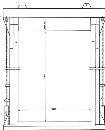
-20-7. LOADING AND END CONDITIONS
7.1.1 ho~din~~y~t~m_<~a£l~i)
In all laboratories a hydraulic system is used for the load
applic-ation on walls and partitions.
Mostly a single load distribution beam is applied so that the total load (for partitions) is equally divided over the different load bearing studs. Only some laboratories apply several short distribution beams, each
of them transmitting the force of one ram.
This raises the question of the test load : is the total load determined by the number of studs multiplied by the load per stud or, is it defined by the load per meter multiplied by the width of the partition. Both approaches can conduct to very different load levels besides the differences in national design codes.
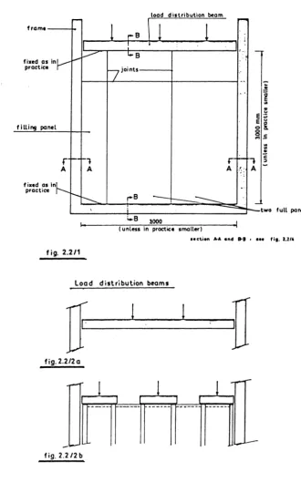
For purposes of harmonization a single load distribution beam over the whole width of the specimen is suggested. This does not cover
particu-lar cases where the studs of a partition are unequally loaded.
The stiffness of the frame has to be considered in direct relation with the load level and therefore a maximum deflection criterion by
maximum load, at least for the horizontal members of the frame, has to be established <see C.T.I.C.M.). In the new draft a value of 1/600 for
defor-mation under design load therefore is proposed.
A similar requirement has to be established concerning a possible
partial rotation of the load distribution beam on the vertical members.
It is observed that very different load capacities (from 8 T to 400 T) are available, linked to very different speeds of the ram : from 0,7 mm/s to 25 mm/s. This can have a minor influence on the stability with a quickly deflecting specimen at the end of the test.
There is a general and very important uncertainty about the overall accuracy of the load applied to the specimen in most laboratories
1°/ The measurement, and mostly also the monitoring of the load level during the test is based on a measuring device, the accuracy of which in general is only estimated.
A variety of different types of apparatuses are used.
2°/ With exception forload cells, positioned between load distribution
beam and specimen, "sensors" are more or less remote from the specimen and subject to faulty measurements caused by friction and/ or pressure drop between measuring point and specimen.
3°/ It is astonishing how few information is available in most
laborat-ories about the extent of friction losses in their loading systems.
4°/ A low stiffness of some frame members, together with excentrical
loading or specimen deformation can cause jamming of the load
distribution beam and hence an uncontrolled increase or decrease of the load.
5°/ Calibration of the loading system in general is insufficient. The
use of loads cells between specimen and load distribution beam, or at least as close as possible to the specimen, seems necessary. Besides that it is necessary to use frames and loading equipment with minimum friction. This friction should be established with load cells by loading and unloading of the specimen in cold state. It was not possible to propose a generally applicable solution on the basis of the visits, because the loading system is closely linked to the design of the furnace.
The question of monitoring the load was not understood properly : it is not clear whether all laboratories do keep constant either the load or the position of the load distribution beam. The latter choice provides
an increasing load with thermal dilatation of the specimen.
From the answers it appears that some laboratories have automatic control over the load level (by keeping the oil pressure constant), others
have manual control. usually monitoring is done on the basis of the same measuring instrument as used for the initial application of the load.
-22-TABLE 4 -LOAD-BEARING WALLS LOADING SYSTEM Rams Load distribution beam Lab. NIJ11ber POSl-111.1na or 1 :,~1ttness fi'OS!tlon tion beam of beam of floatin~ (K} beam 2 tD 4 Top one beam per L top ram or one H
beam
---·· -- -·-2 Bottom one beam VH top 2 Bottom one beam VH bottom --- ·-·- --.--~4 Top 4 short beam VL top
2 (?}
Bottom
one
beam
M
bottom
---4 Bottom one beam VH bottom {u} 1 or Top one beam defl. < top 2 {?} 1/1000 {G) 4 to 8 Top ? l/1000 top {1} 1-3
-{2} 2 Bottom one beam VH bottom (6) 2 tp"
Vfl top 12 Bottomfane
beam M -- ---top ---··-. ~-Accord. Top according {?} top of one to to practice~act. 3 {?}
Top {?} {?} top
--- ---- ··---2 Top one beam HStiffness of
frame
{11}
membegs
u ·~
....
....
D.....
...
0 0...
1-a> > L VH VH H -. ---VH VH H - ·---v
VH VH ~;.. VH --- VH VH VH def. < l/1500 def· < l/1500 VH VH fll 120 1C)z
20 H H H-M
M
L ~--~~
H H L 11.1 75, H H H -- ----H H M Load Speed capaci-of ty rams {max} mm/s
{Ton} 200
8 -- ----·-- - --8 or 20 5 500 ? 20 1 22 25 --- ---400 0,7 220 1,2 50 5 20 12 8 X 30 1 8 X 150 0,25 400 6 200 6 20 6 5 --j -- ---200 ? ? ? --30 15 {K} VH very high H high M medium I ln• Monitoring the load level LOCa-I ACCU-, .. a 1 1Dra-Sensor tion racy tion {type} device Mano-Pump 5 to Load meter 10% cell --- ~ - -- --- Mano-Pump 5 to Load meter 101_ __
teJJ
__
Manom.+ { ?} 5% Load load eEl cell Pres sur at 5% Load gauge ramcell
---Hydr. at 2,5% Load presure ram
F
~J ~::-:
cel-l --Load ? 0,1 cell I Miillom. 3% loaiiCelT or load {?} cell 0,5%M~fr-+
{?} 2,5%I
Load cell~~~, Dynamom
7.1.2 _!!e..£_h.!.nic.!.l_e_!ld_c~n.!!i.!.i~n_!_lt.!.b.!_e_52_
It appears that similar as for non-load-bearing walls and partitions also for load-bearing ones the end conditions with both vertical edges free do not necessarily give the worst results.
Changement of doc. 1202 in this respect should be discussed.
Concerning the mechanical end conditions at top and bottom of walls
and load-bearing partitions, a distinction must be made between the possi-bility of rotation and translation for the load distribution beam and for the other horizontal members on the one hand, and for the horizontal edges of the specimen on the other hand.
The possibility of (partial) rotation and/or (partial) translation of the horizontal members is dependant on the stiffness of the complete frame, on the stiffness of the individual frame members and on the concept of the system.
The lack of precise answers in the questionnaire show the lack of consciousness in several laboratories concerning this aspect of the mechanical end conditions.
The influence of this point has already been discussed under § 2.
The positioning of the walls or partitions against load-distribution beam and against the horizontal members are mostly realised "like in practice" i.e. simply in contact with the frame member for walls and some-times with top and bottom profile screwed for a partition.
As the fixing of top and bottom can influence the static system (buckling length), in the new doc. a strict requirement is introduced that this has to be done like in practice.
It has to be noted that in several laboratories the way of mounting (mechanical and thermal end conditions) for walls (concrete and masonry) is different from the way of mounting for load-bearing partition.
This is partially due to the different practical problems related
with a low level of loading for partitions Cup to 20 T) from the high load level for walls Ci.e. up to 400 T>.
The figures given in the table have to be considered rather as the interpretation of the authors than as precise answers from the laboratories
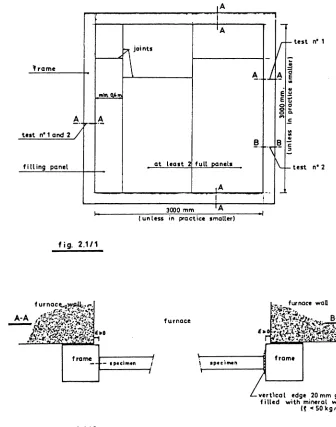
-24-7.1.3 lh~r~al ~ni~o~ditio~s_(~a£l~1)
As it can be seen from the table the thermal end conditions in most laboratories are already satisfied. Exposure of all four edges of a load-bearing wall is important. For bottom and top, reduced heat attack can
influence E and I. For the vertical edges reduced thermal attack can increase R. Therefore clear specifications are given in Part II.
The heat loss to the frame at top and bottom of the specimen is influenced by the thermal characteristics of the frame. Therefore a rough
7.2 El22r~_i!2~l~_22
7.2.1
~o~din~~y~t~m-In several labs the loading system used for floors depends on the type of floor and the magnitude of the load.
As can be seen from the table the loading system in the different
laboratories is quite different. This concerns as well the number of loading points as the contact surface. Especially for dead loads the
contact surface, which should characterise the thermal influence seems insufficient to characterise it. In c.s.T.B. nearly the total specimen surface is covered although the contact surface is only 0,3 %. A solution is presented by limiting the surface of the horizontal projection of the
loading points.
For hydraulic load system A a multipivoted pyramidal load distribu-tion system is necessary in order to guarantee a well defined equal load distribution. In this respect line loads have to be excluded.
This was introduced in the new doc.
The relation between the size of loading spots and the thickness of the floor seems unreasonable because especially thin floors are weak in relation with high local load concentrations, therefore the corresponding
requirement of doc. 1202 was replaced by fixed values of surface area.
During the visits it appeared that the load distribution did not provide statically equivalent loading (maximum loading moment and maximum shear forces>.
The text of the revised doc. has been closer specified.
7.2.2
Ini~o~ditio~s-In the discussion it appeared that the end conditions with floors supported at two sides do not give necessarily the worst results.
A changement of doc. 1202 in this respect (3 sides fi~ed edges in practice)
should be discussed.
In most laboratories free deflection is guaranteed but the thermal elongation in several laboratories is partially prevented by friction. In
---Great differences have been observed concerning the unheated ends of the floors. As this can have great influence maximum values have been introduced.
Most of the remarks made for floors are also applicable for beams, especially the problem of the cold edges.
7.3.1 hO~din~
~y~t~m-Except in TRADA all Laboratories used hydraulic loading systems.
In some Laboratories it was noted that in the Load distribution system no provision is made to avoid changes in the Loading system when the specimen deforms (elongation and deflection). Thus additional horizontal components are created.
The load distribution system must be isostatic by design. A requir-ement in this direction is introduced in Part Il.
In two labs the topping of the beam was cast in one block and was more or Less fixed to the beam with anchors. By this arrangement the topping will overtake at least an undeterminate part of the load bearing
function.
In part IIa detailed description and mandatory requirement for the topping are introduced.
This concerns also the nature of the topping in relation with the heat Loss.
Composite floor-beam elements are tested in the same way as floors without additional topping.
During the visits, no problems with torsional deformation or lateral
buckling were observed.
If torsional deformation or a lateral buckling in a test on a
single beam are expected provision Like in practice can be made in order to avoid this. The Load applied during the test shall be adopted
accordingly (composite structure).
7.3.2
In most laboratories the stiffness of the frame seemed sufficient at least in one direction but there were great differences in the end
conditions and the way of mounting the specimen. Especially the possibility of rotation or restrained are not fully defined in most cases.
Where the possibility of rotation is intended, this was not fully
achieved and the same is valid for end restrained.
Concerning clearly defined end conditions a statement is made in due. 1202. However it is considered that this aim cannot be achieved without important and expensive changements of the equipment. The consequence of the existing differences are judged of great influence on the measured R values, because it influences strongly the buckling length of the specimen, and by this the load bearing capacity.
An other point of similar importance is the axiality, resp.
excentricity of the load. By excentric loads, bending moments and torsions are introduced which will cause an earlier failure.
Only in two labs there were special means to guarantee exact centricity, in one other lab a well defined excentricity was applied in
order to meet excentricities which occur in practice and in order to improve the reproductibility during the tests. For harmonization purpose it is absolutely necessary to give clear instructions on this. In the revised doc. therefore it is suggested to check the situation before each test by using straingauges. An alternative solution could be to impose the maximum excentricity allowed for centrically loaded columns and to describe the way how to achieve this.
It was questionned whether in all cases testing of the two static
systems will provide results relevant to practice.
In the revised document it is suggested to check which of the two static systems will give the worst results and not to carry out the other test. An other suggestion was to make a general choice for the static system for the test. T.N.O. offered to prepare a document providing the
Differences of 0 to 0,6 m were observed between heated length and calculation length, the calculation length being defined as the length between hinges and restrained ends.
It is expected that this causes great differences in R-values. Also this problem can not be solved without important changes to the equipment.
In addition also the heat loss of the column ends to the surrounding (e.g.) concrete blocks, steel plates, unheated column ends> was different.
The above-mentioned points show that for columns harmonization is restricted by the differences in the existing equipments.
Comparable results can only be expected by identical furnaces and loading equipments. It is therefore suggested to prepare a design of a furnace which should be followed when new furnaces are built.
-32-8 : COLUMNS -LOADING SYSTEM AND END CONDITIONS Max. load capacity (t)
---NW Rom
very high H high M medium L low
400
-
suo
-
-
-
250 220 200 400-
400-
?-Speed
of
rams (mm/S)
----1,2
-
?-
-
-
0,4 1,2 2 6-
?-
?-Stiffness
Heated
of
frame
length minus calculation length
8. TEST LOAD (see table 9)
It is evident that the test Load has an important influence on the fire resistance time of a Load bearing element.
In most Laboratories the test Loads are calculated following national design codes. Therefore differences between these codes influence the test Load and hence the test result. It is out of the scope of this
study to compare the national design codes.
Nevertheless it seemed to be usefull to have some comparative data on the Loading calculations.
Therefore the Laboratories have been asked to give the calculations
of the test Load for four Load bearing elements. The elements were :
a) a steel beam - simply supported;
b) steel column- one end hinged, the other end fully restrained;
c) steel column- both ends fully restrained;
d) timber stud wall.
With the exception of Italy answers were received from all the participating countries. The data are summarized in table 9.
For the steel beam the table shows neglectable differences between the test Load calculated.
For the steel columns the test Loads calculated show differences up
to about 200 kN on a test Load of app. 1 000 kN.
Extreme great differences are found for the timber stud wall. It is noted that in some countries the contribution of the Lining materials are not taken into account by the calculation of the test Load of a timber stud wall. Besides, the situation in Denmark - a great
difference between calculated Load and test Load in practice - is of interest. From this simple investigation on test Loads can be Learned that full harmonization of fire resistance test requires prior harmonization of
design codes within the EEC.
However, according to the statement in § 5.2 of the revised document
1202 the test results are applicable with the Limitation to the Load appli-ed during the test.
This has to be mentioned expressively in the test report.
-34-9. Summary answers received on questionnaire concerning test load on a beam, column and partition. Country Test load in kN Steel columns Str:o<>l ~f";:lffi Wooden P.art1tion
Ir"
I
J3m 3mx 3mDICO
IC. HEB 180 ~ HEB 11:SU HEB ·11:SU 2 991 kN 1063 kN 33,4 kN/m -960 kN 1030 kN 37 kN/m 2 66,6 kN/m'~ (pract.) ,, 970 kN 1019 kN 37,7 kN/m2~;:;f~~,;~ ~~~;o~~~:l
France 1140 kN 1198 kN 34 kN/m 2 25,83 kNIIrf2 969 kN 1136 kN 34,1 kN/m 2 300 kNim 2 , __ _, -
r-Italy The
Nether-kN/m 2 lands 1042 kN 1147 kN 4,1 42 kN/m Mini mum value 1019 kN z 2 test load 960 kN 994 kN 3,4 kN/m 23,2 kN/m Maximum value 2 2 test lo8d 1140 kN 1198 kN 4,1 kN/m 66,6 kN/m· Calculation method Remarks Construction partition Studs 60x100mm distanct. between centrel ines 600mm. Particle board 16 mm on both sides. No design code available for timber structures. Load on request of sponsor Columns and beams test Load on partition DS 412 and DS 410 in practice 10-40% of design load normally <7-26 kN/m2.) Columns and beams BS 449 part 2
-1969. Calc.
ace. l'egles de Partition: Particle calcul des constru-board is not taken into ctions en acier. account by calculation of test load. Columns and beam Partition : DIN 1050. 15.8 kNir~
2 <nail
distance 40 mm) Partition DIN 1052 (O"..L= 2,5 N/mm2 ----;---'
--Columns and beam TGB-Diameter nails 8 4 mm1972-steel-partition TGB
1972
9. CRITERIA AND APPLICATION OF TEST RESULTS
9.1 fri!~ri~
For load bearing elements which are subjected to bending two different deformation criteria are given for stability.
The one is for simply supported elements, the other for hyperstatic elements. A criterion imposed to avoid a special danger in practice cannot be dependend on the statical system. Therefore it should be considered to apply the same delfection criterion (either deflection rate or a maximum deflection) for both cases.
The existing document 1202 does not contain explricitly information on extrapolation and interpolation of test results.
Implicitly extrapolation is allowed by the regulation concerning
size of specimen : the requirement to choose a height and width of 3 m for a wall specimen it it is in practice greater, implies an unlimited possibi-lity to extrapolate the dimensions to a greater height.
This requirements excludes as well the possibility of extrapolation
to lower dimensions as the possibility of any extrapolation from speciem which have lower dimensions than 3 m x 3 m.
From a technical point of view it seems not acceptable to use this extrapolat;on rule without limitation.
So one cannot accord the same classification to elements with essential higher dimensions than the tested element.
It is clear that for practical reasons extrapolation of test results is necessary.
These extrapolation rules should cover the field of higher and lower dimensions.
In some countries extrapolation rules exist for some elements and these rules are different from country to country.
For trade, harmonization in this field, is of the same importance as harmonization of the test method.
This work is not covered by this document. It will require an extensive study. In the opinion of the authors it should be started with a detailed questionnaire on the existing extrapolation rules and habits
-36-in the different countries cover-36-ing all possibilities of extrapolation
e.g. dimensions, load, massivity factor, etc.
In the Light of the above mentioned problems the following points
should be discussed
non-Load bearing walls and partitions extrapolation to a greater height;
Limitation of the
for Load bearing elements : the extrapolation Limitations should
take into account the static system and the load Level;
10. REMARKS ON TEST REPORT
A basic requirement for international acknowledgement of test results is that the test reports contain all necessary information in
an understandable and harmonized way. Therefore the actual way of drafting test reports by the different laboratories was compared.
A survey of these reports has been given in table 10.
Special attention was given to the following points :
a) description of the test specimen <*ncluding drawings and details);
b) information on material properties;
cl description of thermal and mechanical end conditions;
d) test load and its calculation;
e) test procedure;
f) observations during and after the test.
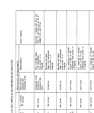
The results of the study have been summarized in the tables 11-15.
-38-Table
10.
Survey
of
test
reports
1Countzy
1..._
of
x.boratory
Load
bearing
I
Other
It•----+---~~-+---+-="'---+====='--+""'a'-'1.;;_1/partition
l&elqiua
RUG
Den.ark
UAN'l'BS'I'
IBnqland
FIRI'O TIWlA WARRINGTON Yanley
Lance
I
CS!rB
~
l'U-»raunachwet~
MPA
-NW
S.F.M.
I
I
I
I
I
I
Glazed
door
P.M.P.A.
Iuly
L.,..
~-1
:.
1.1.
I
..
I
I ~ 0 I
Name
of
laboratory RUG TU Braun- schweig Warrington CSTB CSEA
Specimen
Protected steel beam Protected steel beam unprotec- ted
steel
beam
Protected steel beam Special roof beam
~ Summary of reports on beams Test specimen ~C;~~~~~~ction ~;a:~~~:me~etai ls Missing : way of fixing of the protection cladding (sprayed, by hand etc.> scatter in thickness of the protection. sufficient sufficient sufficient sufficient sufficient sufficient sufficient sufficient sufficient poor dimensions etai ls of insuff. ceiling etc given. ot given. End conditions Material properties IM•a.urod "'"' nn f e<t Th rmal Mechanical materials beam lenath of supports restrafned density relative thickness mechanical heated unheated humidity properties part part not not given missing 6000 mm 2x350 mm not given not given given given steel pro-perties at
normal temperature
given given given missing 4750 mm 2x125 mm two rolling Beams tested steel pro-supports complete un-perties at restrained.
normal temperature jmissing
2 rolling not applicable steel pro-4000 mm 2x392 mm supports rotation perties at unrestrained. rormal Elongation temperature unknown 3740 mm 2x250 mm supported by Elongation I-beams partly not given in the report
restrained (by
NIIH
of
laboratory RUG TU Braun- schweig Warrington CSTB CSEA
Specimen Protected steel
beam
Protected steel
beam
Unprotected steel
beam
Protected steel
beam
Special roof
beam Table 118. SuiMiary of reports on bea•s Test load Test method Ca CUL1t10n Loadsyste• T1me temp. curve of Diagra11 Tolerance Integral test load or temp.distr. curve table
within furnace
Principles No detailed No data concerning time temp. of calcul-description curve in the report ation are or drawing
given (permiss- able stresses 14
kNtm2> ace. to No detailed No data concerning time German description temperature curve in standard or drawing report • DIN 1050 last fall H = 160
N/mm2. Calcula- tion
is
missing Complete
No detailed Mean furn. not given not given calc. description temp.given in the in the given in or drawing in diagr. report report
the report. Calc.
of No detailed All thermocouple not given tut load description readings given in the not given or drawing in a diagram report. in report tested not Mean furn. not given not given unloaded applicable temp.given in the in the in report report report ObservationS and Measurements Furnace 02 Observ. Measure•ents Other reurks pressure content
in furnace
ace. to missing Short Steel temp. Topping of NBN 713 given in steel bea111 020 report given in 20 + 5 <diagram> Pa missing No reg-deflection istration diagram ace. to miss in Short Steel temp. Topping of DIN 4102 and deflec-steel beam 10 Pa, no tion given given in registra-in diagram. report ..
tion. not
I
.,.,.
1\J II
I i IName
of
lab. RUG FIRTO BAM FMPA CSEA CSTB CTICM
protected steel column protected steel column Rectangular steel column filled
with
concrete protected steel column steel column protected with
an
intumes- cent paint steel column protecte.d with intumes- cent
paint
protected steel column
To Constr< ction f Description Drawings suffident suff. sufficient suff. sufficient suff. sufficient suff. sufficient
suff.
i
extensive isuff. suff. suff. Table 12A Summary of test reports on
columns
-~---·----•n•dm•n Material orooerties. Measured values on day of test Protecting materials. column Details density relative thickness mechanical humidity properties missing given not givor g1ven steel prop-joints erties at between normal temp.
rock- wool plates suff.
given iven given not given suff. Yield strength steel and not applicable
compressive strength concrete
given suff. given ~iven given steel propertie at normal temp. not given
missing: way
in not applicable given not given
which paint
is
applied. suff.
not applicable given not given not applicable uff. given not given not given iven ,, conditions Thermal Mechanical Length of length of Top Bottom heated unheated part part 3780 mm 0 mm fulLy fully restr-restrained ained not given not giver'l in com-incomplete t plete description descr- iption 3000 mm 3600 - incom-incomplete 3000 = plete description = 600 mm descri- ption 3360 mm 3845 -rotation fully 3360 = in one restrained = 485 mm
direct- ion possible
N 0 T G I V E N I N T H E R E P ORT 3300 mm 3600 -inc om-incomplete 3000 = plete description = 600 mm descr-and drawing
iption and drawing
3600 mm 3600-in com-incomplete 3100 = plete description = sao mm descr-and drawing
iption and
Table 12 B. sun~n~ary of test reports 00 columns. Name of Lab. Specimen Calculatio Ob ' t; " "
..
' "Other remarks test load Control 0 Furnace
o,
Observ. Measurements urnace te111p pressure content ;, furn Steel Elongation RUG protected given ;, oot given 20+5,,
oot given suffic. measured given ;,.
Steel te11p • only measured ;, th• steel rep. ace. with 8 diagram middle part of column'"'
oot ;, column to NBN ther1110-upper'"'
tower part. est .001 coup. euler 1. results Both ends ;, fully diagram FIRTO protected given ;, only.
oot oot given suffic. measured given ;,.
Reloading after 24 hours. Persons steel rep. ace. diagral'll given with 12 diagram who witnessed th• test "' column to BS 449: thermo-11entioned ;, th• report. part,,
furnace coup. 1969 te111p. mean'"'
effective ;, th• max. temp Length 0, 7 report given ;, 1 euler.th• report
CSTB steel column only calc. furn. oot given suffic. steel given ;,
.
protected meth.given temp. given temps. diagram with intu-;, th• given mescent n!port. in a measured paintdiagram (all readings)
CTICJII protected only main furnace wns oot given suffic. measured given ;,
.
steel points of temp.,,
with 9 diagram column th• calc. given ;, diagram thermo-"' given.
diagram given coup. <aLL ;, th• diagram readings) report with ollreadings ;,
th• report BAM rectangular oot given Furnace oot given suffic. steel
.
given;,
.
steel column ;, th• temp. given con cr. diagram filled with report given ;, temp. ;, (mean.
diagram value andindividual readings)
FI'IPA protected the main Furn.te111p. 10Pa
"
oot given suffic. measured recorded steel column points of given ;,.
0,75 Ill with 6 during whole tho calc. diagram from thermo-heating are given (mean val-top coup."'
'"'
column
diagram
individual
with
oll
readings ;,