Steel Structural Applications.
White Rose Research Online URL for this paper: http://eprints.whiterose.ac.uk/86777/
Version: Accepted Version
Proceedings Paper:
Demetriou, D, Nikitas, N and Tsavdaridis, KD (2015) A Novel Hybrid Semi-Active Mass Damper for Lightweight Steel Structural Applications. In: The 8th International Conference on Advances in Steel Structures. IJSSD Symposium on Progress in Structural Stability and Dynamics, 21-24 Jul 2015, Lisbon, Portugal. .
eprints@whiterose.ac.uk https://eprints.whiterose.ac.uk/
Reuse
Unless indicated otherwise, fulltext items are protected by copyright with all rights reserved. The copyright exception in section 29 of the Copyright, Designs and Patents Act 1988 allows the making of a single copy solely for the purpose of non-commercial research or private study within the limits of fair dealing. The publisher or other rights-holder may allow further reproduction and re-use of this version - refer to the White Rose Research Online record for this item. Where records identify the publisher as the copyright holder, users can verify any specific terms of use on the publisher’s website.
Takedown
If you consider content in White Rose Research Online to be in breach of UK law, please notify us by
STRUCTURAL STABILITY AND DYNAMICS Lisbon, Portugal, July 22-24, 2015
A NOVEL HYBRID SEMI-ACTIVE TUNED MASS DAMPER FOR
LIGHTWEIGHT STEEL STRUCTURAL APPLICATIONS
Demetris Demetriou*, Nikolaos Nikitas* and Konstantinos Daniel Tsavdaridis*
* University of Leeds, School of Civil Engineering, United Kingdom cn09dd@leeds.ac.uk, N.Nikitas@leeds.ac.uk, K.Tsavdaridis@leeds.ac.uk
Keywords: Vibration control; Semi-active; Hybrid vibration mitigation systems; High-rise structures Abstract. This paper proposes the application of a novel hybrid semi-active vibration absorber for the control of multistorey vibration prone structures under wind excitation. It is shown that the novel device outperforms the traditional tuned mass damper (TMD) by achieving performance gains similar to an active mass damper (AMD) while maintaining robustness at the extra benefit of considerably less energy and actuation demands, satisfying both strict serviceability and sustainability requirements often govern most lightweight steel structural applications.
1 INTRODUCTION
Almost a century after the invention of the dynamic vibration absorber (DVA), tuned mass dampers (TMD) are found to be amongst the most popular methods for civil engineering structural control. While TMDs have been shown to be successful at alleviating structural response under generic dynamic loading, such devices being tuned to a single vibration mode of the structure are limited to a narrow band of operating frequencies that in turn could
compromise the system’s attenuation capacity when excited beyond this targeted mode. Additionally, such devices being sensitive to de-tuning either as a result of material degradation, structural damage or simply due to bad modelling practices, compromise further their vibration attenuation capacity. In this regard, over the last few decades, attempts have been made to improve the performance of the traditional passive TMD by substituting its passive elements with active and semi-active components. Clearly, active mass dampers (AMD) have been shown to outperform purely passive and semi-active dampers (STMD) when it comes to vibration attenuation, yet this performance enhancement comes at the expense of considerable power -force demands and reliability. As a result, hybrid mass dampers (HMDs) (these being purely passive TMDs working in conjunction with active control elements) are found in many practical applications. Studies such as [1-3] are a few amongst the many illustrating the performance gains of the use of HMDs on structural systems under both earthquake and wind excitations. Yet, similarly to the AMD the performance objective is achieved at the expense of considerable power demands.
2 MODELING PRINCIPLES
2.1 Modeling of passive/active and semi-active dampers
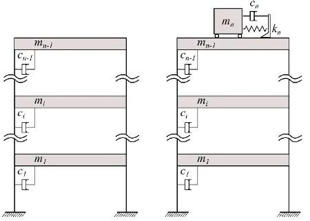
Modelling the novel SHMD device requires a thorough understanding of the modelling principles of its passive, active and semi-active counterparts. Starting from the straightforward passive system, the operational principle of a simple TMD can be explained by considering a simple n-DOF sway structure as the one depicted in Fig. 1. The dynamic behaviour of such a system when subjected to an arbitrary disturbance is fully captured by its matrix equation of motion:
( ) ( ) ( ) ( ) ( )
Mx t Cx t Kx t Bu t Dd t (1)
where each overdot declares single differentiation with respect to t , M, C and K are the
[image:3.595.183.408.396.557.2]n n mass, damping, and stiffness matrices respectively; x t( ) and d t( )are in order the displacement, and external force n1 column vectors; u t( ) is the single scalar control force and B (n1) and D (n n ) are the influence matrices assigning the control and external force contributions respectively to the individual DOFs. For each DOF in x t( ) being the lateral displacement of the ith (i1,...,n) mass, Mtrivially becomes diagonal, while for the classical viscous damping considered (and connections as in Fig. 1) the damping matrix C attains a form identical to the symmetric stiffness matrix K. Without any loss of generality the mass damper device is attached to the (n1)th DOF and its motion constitutes thenth DOF.
Figure 1: Simple (n1)-storey example building where a TMD is employed.
The matrix Eq. (1) could describe a system equipped with any type of viscous dynamic absorbing device. The difference between the passive, active and semi-active schemes would exclusively be captured by the nature of the control force u t( ). It would be probably more appropriate for the passive case to term u t( ) as the interaction force, yet for economy in presentation and homogeneity, the term control is used throughout. To facilitate the derivation of a semi-active control force, it would be beneficial to first consider the case of a purely passive TMD. When the TMD is attached to the system of interest u t( ) takes the form of a purely passive action, u tp( )resulting solely from the motion of the absorber’s mass. This
passive force which couples the damper to the rest of the system can be mathematically expressed as:
( ) ( ) ( )
p n r n r
In Eq. (2) ,c is the constant scalar damping coefficient and n k is the constant scalar spring n
stiffness of the TMD (as depicted in Fig. 1), while x t andr( ) x t are respectively the relative r( )
velocity and displacement between the th
n and (n1)th DOFs. It should be also noted that the
n-element B matrix becomes
0... 1 1
T. When an active control system is considered, thecontrol force takes the form of a desired action, u t determined via a control algorithm such a( ) as the Linear-Quadratic-Regulator (LQR), PID or any similar control algorithm. For an AMD,
the desired force is the summation of the passive forces generated by the mass damper’s
motion and an additional external force provided by means of mechanical actuation. Because the dynamic characteristics of the mass damper remain unaltered and the desired interaction force, u t has been already calculated by the control algorithm, the required actuation force, a( )
f ( )a t can be readily determined from:
( ) ( ) ( ) f ( )
a n r n r a
u t c x t k x t t (3)
For purely active systems, the values of c and n k can take zero values, resulting to the n control action to be equal to the actuation force:
( ) f ( )
a a
u t t (4)
However, the requirement of a fail-safe mechanism dictates that in most practical applications the values of c and n k would be of similar magnitude to the passive TMD equivalents. The n resulting system that combines the passive TMD and the purely active AMD (see Eq. (3)) is known as a hybrid system.
For the case of semi-active control, obtaining the control action involves the calculation of an equivalent active force which at the same time can be physically realised by the semi-active device. In this regard, because of the fact that no energy can be added directly to the system, the semi-active device will produce control forces only when required i.e. when the damper is requested to “consume” energy. Having already obtained an equivalent active force from Eq. (4), the final step is to apply active force saturation limits such that the semi-active control force, usa( )t is calculated by [4]:
1 sgn[f ( ) ( )] ( ) f ( )
2
a r
sa a
t x t
u t t (5)
1 for 0 sgn[f ( ) ( )] sgn( ( ))
1 for 0
a
a r a
a
q t x t q t
q (6)
The product of f ( ) ( )a t x t is the power,r q , of the whole active system device. Similarly, the a power of just the semi-active component is defined as the product of the force that can be physically translated by the device, usa( )t and its relative velocity,x t : r( )
( ) ( ) ( )0
sa sa r
A schematic representation of the power time histories of both an actively and a semi-actively controlled devices is shown in Fig. 2. It can be observed that the active device has the advantage of both negative and positive powers, while the semi-active device only consumes power. This reinforces the fact that an active control scheme can potentially also add energy to the system whereas a semi-active scheme can only dissipate energy.
Figure 2: Indicative example of the “power” scheme/demand practiced in semi-active control (see Eqs. (5-7)). The device only performs to dissipate energy (qa, qsa in Watt).
So far, the principle of obtaining a “desired” control force to be provided by a semi-active device has been discussed. When a variable damping (VD) STMD is considered, the chosen way of achieving optimum performance is by appropriately timely adjusting the damping coefficient of the device within bands, in order for the required control force to be reached. By referring back to the system presented in Fig. 1, one can express the semi-active damping force contribution ascsa( )t x t . An inspection of Eq. (7) easily leads tor( ) csa( )t 0. Updating Eq. (3), the resulting overall control force provided at each time instant by a VD-STMD can be expressed mathematically as:
( )( ( ) ) ( ) ( )
a sa n r n r
u t c t c x t k x t (8)
In Eq. (8) the time varying semi-active damping coefficient, csa( )t is the only unknown. Therefore, calculating the real-time variation of the damping coefficient is straightforward.
2.2 Modeling the semi-active hybrid mass damper
Through the use of a SHMD the energy dissipation capacity of a semi-active device is exploited and energy is added only when required through force actuators. The main difference between an AMD and a SHMD lies in the fact that the actuators of the AMD both add and dissipate energy whereas the forcing provision of the SHMD can only add energy. It is worth noting that dissipating energy using active actuators requires power of the order of kWatt, whereas dissipating energy using semi-active devices requires power of just a few Watt [5]. The steps required for the calculation of the envisaged control action,ushmd( )t are:
3. Calculate an additional active force using strictly active control algorithms and limit the capacity of the actuator such that it can only add power:
( )f ( ) ( )0
a a r
q t t x t (9)
It is noteworthy, that enabling performance of the actuator can be achieved by using Eq. (5) and simply inverting the sign conditions of Eq. (6) such that:
1 for 0 sgn( ( ))
1 for 0
a a
a
q q t
q (10)
Alternatively, performance conditions/limitations can be placed using a direct output control algorithm (groundhook) (see section 3).
4. Incorporate both active and semi-active forces to the system using:
( ) ( ) f ( )
shmd sa a
u t u t t (11)
3 CONTROL METHODS
As discussed in the previous sections, obtaining the semi-active and active actions is achieved via control algorithms. For the purely active control case, the algorithm of choice is the LQR whereas for the case of semi-active control the algorithm of choice is the velocity based groundhook algorithm which belongs to the category of direct output feedback controllers (i.e. the control actions are calculated based on a limited number of measurements). The choice of direct output feedback controller for the case of semi-active control is based on the reduction of computational effort required for the online calculation of Eqs. (5) and (6).
3.1 Semi-active control / Groundhook
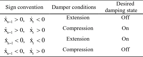
[image:6.595.174.420.584.683.2]In a groundhook control scheme, the directionality condition of the forces needs to be examined in order to determine the required control action. Depending on the motion of the mass of the damper and the structure and without the loss of generality, four cases are identified and damper forces are calculated in accordance to Table 1 [6]:
Table 1: Groundhook Control strategy.
Sign convention Damper conditions Desired damping state
1 0, 0
n r
x x Extension Off
1 0, 0
n r
x x Compression On
1 0, 0
n r
x x Extension On
1 0, 0
n r
x x Compression Off
Summarising the conditions, this velocity based groundhook (VBG) control rationale is mathematically captured by:
1 0 ( )
n r sa
1 0 ( )
n r sa
x x c t Min (13)
Alternatively, it is possible to replace the velocity of the unsprung damper mass by a primary system displacement term, resulting to displacement based (DBG) control, mathematically expressed as:
1 0 ( )
n r sa
x x c t Max (14)
1 0 ( )
n r sa
x x c t Min (15)
The semi-active control force is thus calculated by:
( ) ( )
sa sa r
u t c t x (16)
3.2 Active control / LQR
The LQR works on the basis of minimising a quadratic performance index through manipulation and optimisation of the control input vector Bu t( ), see Eq. (1). The performance
index used in structural control applications when working with the state space formulation is defined as [7]:
0
[ ( ) ( ) ( ( )) ( ( ))]
tf T TJ x t Qx t Bu t R Bu t dt (17)
In Eq. (17), Q and Rare weighting matrices relating to the trade-off between control effectiveness and control energy consumption respectively, tf is the control period of consideration. By manipulating the magnitudes of Q and R, better disturbance rejection can be achieved at the expense of control effort and vice versa. For example, a better disturbance rejection and minimization of the state error could be achieved by increasing the magnitude of the elements of the Q matrix relative to the R matrix. In contrast, increasing the magnitude of the Rrelative to the Q matrix would yield smaller control forces thus less control effort as well as reduced disturbance rejection. The values of elements of these matrices are selected such that Q is a positive semi-definite matrix and R is a positive definite matrix. By doing so, Eq. (17) will never yield a negative result. Once the weighting matrices have been obtained, the problem reduces to the classical optimal problem where the control gain G is calculated by:
1
1 2
T
G R E P (18)
where, P is the Riccati matrix found by solving the algebraic Riccati equation:
1
1
2 0 2
T T
PA PER E P A P Q (19)
1 1 1
0 0
,
I
A E
M K M C M B (20)
with I being the identity matrix. When full-state feedback is available, the control force is calculated based on:
( )
u t GX (21)
3.2 Semi-active hybrid control
For the SHMD case the semi-active force component is calculated using a VBG controller, whereas, the active force, component,uactive( )t is calculated using a LQR and its capacity is restricted to only producing power in accordance to Eq. (9) via another VBG such that:
x xn1 r 0 uactive( )t u ta( ) (22)
1 0 ( ) 0
n r active
x x u t (23)
4 NUMERICAL INVESTIGATION
4.1 Structural configuration
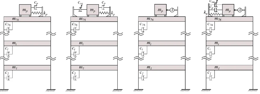
[image:8.595.73.527.517.682.2]The effectiveness of the proposed device is illustrated through numerical simulations on the 76-storey benchmark wind-sensitive sway structure proposed by Yang et al. [8]. The structure is excited by across wind loading for a duration of 900s, enough for the response to establish its stationary properties. In this study, four alternatives, namely: passive (TMD), semi-active (STMD), active (AMD) and semi-active hybrid (SHMD) controlled structures were used to demonstrate the performance gains of the new device. The configuration of all the mitigation measures are shown in Fig. 3.
Figure 3: Ensemble of all the different control options (i.e. TMD, STMD, AMD, SHMD) studied herein for the model 76-storey structure of Yang et al. [8].
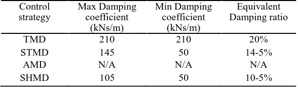
as to limit strokes to a maximum of 95 cm. As a matter of fact, since the damper stroke is the main performance limiting factor, the assessment of the devices that can alter online their damping capacity was performed on the basis of a maximum stroke of 70cm. This is indicated by the performance criterion J 11 (≈ 2.11) (see section 4.2). The resulting damping coefficients that equalize the maximum strokes are outlined below:
Table 2. Damping coefficients
Control strategy
Max Damping coefficient
(kNs/m)
Min Damping coefficient
(kNs/m)
Equivalent Damping ratio
TMD 210 210 20%
STMD 145 50 14-5%
AMD N/A N/A N/A
SHMD 105 50 10-5%
4.2 Evaluation criteria
The comparison of the different control strategies is based on the stationary response properties of the different control structures. From the response time histories, the rms and peak accelerations and displacements at different storeys were obtained. From the obtained values, twelve performance criteria were identified. The first criterion,J appraises the ability 1 of the control strategy to reduce rms accelerations:
1max( x1, x30,x50,x55,x60,x65,x70,x75) /x75o
J (24)
where xi is the rms acceleration of the th
i storey and x75o is the rms acceleration of the 75th floor (last occupied floor) without control. The second performance criterion evaluates the average performance of six floors above the 49th floor:
2
1
( / ); 6
xi xioi
J (25)
For i 50,55, 60, 65, 70, 75; where, xio is the rms of the i floor without control. The third th
and fourth performance indices assess the ability of the control system to reduce top floor displacements:
3 x76/x76o
J (26)
4
1
( / ); 7
xi xioi
J (27)
For i 50,55, 60, 65, 70, 75, 76; where, xi is the rms displacement of the i floor, th xio is the
rms displacement of the i storey without control and th x76o is 10.136 cm. The fifth and sixth indices take into account the rms stroke of the damper (i.e. i77) and the average power respectively:
5 x77/x76o
2 1/2
6 77
0
1
{ [ ( ) ( )] }
T
J x t u t dt
T (29)
In which, x77 is the rms stroke of the damper, x77( )t is the damper velocity and T is the total time of integration. Similarly to the first performance indices, the next four criteria (i.e.
7
J toJ ) evaluate the performance in terms of peak response quantities: 10
7 max( p1, p30, p50, p55, p60, p65, p70, p75) / p75o
J x x x x x x x x x (30)
8
1
( , / ,); 6
pi pioi
J x x (31)
For i 50,55, 60, 65, 70, 75;
9 p76/ p76o
J x x (32)
10
1
( / ); 7
pi pioi
J x x (33)
For i 50,55, 60, 65, 70, 75, 76; where, xpi is the peak acceleration of the i floor with th
control and xpiois the peak acceleration of the i floor without control. Similarly, th xpi is the
peak displacement of the i floor and th xpio is the peak displacement of the i floor without th control. The 11th criterion assesses the ability of the control strategy to minimise the stroke of the damper:
11 p77/ p76o
J x x (34)
In which, xp77 is the peak stroke of the actuator. The last criterion examines the control effort
by calculating the maximum required power by:
12max 77( ) ( )
J x t u t (35)
From the above defined criteria, it can be observed that the better the performance, the smaller the performance indices J J1, 2,..,J [8]. 12
5 SIMULATION RESULTS AND CONCLUSIONS
Figure 4: Illustration of the performance of different control measures in terms of displacement and acceleration at different floor levels.
The results indicate that for approximately the same damper strokes, the SHMD equipped structure is able to achieve similar performance to the AMD equipped one, while clearly outperforming the semi-actively controlled alternative. With reference to Table 3, it is also evident that the SHMD device requires much less energy and force demands for achieving the aforementioned performance increase. As a matter of fact, the SHMD device requires approximately 10% of the total energy required by the AMD device. This can be explained by the large amount of energy required to be dissipated by the active actuators (approximately
5400 kJ ≈ 2.2 kWh or 75% of the total energy required), which for the case of SHMD control occurs at the expense of a few Wh. Additionally, the active actuators of the SHMD require just 779 kJ ≈ 0.2 kWh as opposed to the AMD actuators that require 1915 kJ ≈ 0.53 kWh (the remaining 25% of the required energy).
Table 3. Performance criteria overview
Performance index TMD STMD AMD SHMD
1
J 1.52 2.58 2.85 2.38
2
J 0.58 0.48 0.43 0.42
3
J 0.68 0.62 0.58 0.57
4
J 0.58 0.53 0.50 0.49
5
J 1.26 2.19 2.53 2.09
6
J N/A N/A 1.91 9.66
7
J 1.49 2.44 2.31 2.57
8
J 0.64 0.51 0.45 0.41
9
J 0.68 0.57 0.51 0.53
10
J 0.59 0.48 0.44 0.45
11
J 1.32 2.17 2.15 2.10
12
J N/A N/A 33.03 54.15
Max u t( )(kN) N/A N/A 300 100
[image:11.595.109.487.450.769.2]6 REFERENCES
[1] Fujinami T, Saito Y, Masayuki M, Koike Y, Tanida K., A hybrid mass damper system controlled by Hinfity control theory for reducing bending-torsion vibration of an actual building. Earthquake Engineering & Structural Dynamics. 2001;30:1639-43.
[2] Watakabe M, Tohdp M, Chiba O, Izumi N, Ebisawa H, Fujita T. Response control performance of a hybrid mass damper applied to a tall building. Earthquake Engineering and Structural Dynamics. 2001;30:1655-76.
[3] Nakamura Y, Tanaka K, Nakayama M, Fujita T. Hybrid mass dampers using two types of electric servomotors:AC servomotors and linear-induction servomotors. Earthquake Engineering and Structural Dynamics. 2001;30:1719-43.
[4] Hrovat D, Barak P, Rabins M. Semi-active versus passive or active tuned mass dampers for structural control. Journal of Engineering Mechanics. 1983;109:691-705.
[5] Nagarajaiah S, Varadarajan N. Short time Fourier transform algorithm for wind response control of buildings with variable stiffness TMD. Engineering Structures. 2005;27:431-41.
[6] Koo JH. Using magneto-rheological dampers in semiactive tuned vibration absorbers to control structural vibrations. Phd thesis, Blacksburg,Virginia: Virginia Polytechnic Institute and State University; 2003.
[7] Soong TT. Active Structural Control: Theory and Practice. New York: John Wiley & Sons,Inc.; 1990.