This is a repository copy of
Active phase-nulling of the self-mixing phase in a terahertz
frequency quantum cascade laser
.
White Rose Research Online URL for this paper:
http://eprints.whiterose.ac.uk/83211/
Version: Accepted Version
Article:
Dean, P, Keeley, J, Valavanis, A et al. (9 more authors) (2015) Active phase-nulling of the
self-mixing phase in a terahertz frequency quantum cascade laser. Optics Letters, 40 (6).
950 - 953. ISSN 1539-4794
https://doi.org/10.1364/OL.40.000950
[email protected] https://eprints.whiterose.ac.uk/
Reuse
Unless indicated otherwise, fulltext items are protected by copyright with all rights reserved. The copyright exception in section 29 of the Copyright, Designs and Patents Act 1988 allows the making of a single copy solely for the purpose of non-commercial research or private study within the limits of fair dealing. The publisher or other rights-holder may allow further reproduction and re-use of this version - refer to the White Rose Research Online record for this item. Where records identify the publisher as the copyright holder, users can verify any specific terms of use on the publisher’s website.
Takedown
If you consider content in White Rose Research Online to be in breach of UK law, please notify us by
Active phase
-
nulling of the self
-
mixing phase in a
terahertz frequency quantum cascade laser
P. Dean,1* J. Keeley,1 A. Valavanis,1 K. Bertling,2 Y. L. Lim,2 T. Taimre,3 R. Alhathlool,1 L. H. Li,1 D. Indjin,1A. D. Rakić,2 E. H. Linfield1 and A. G. Davies1
1
School of Electronic and Electrical Engineering, University of Leeds, Leeds, LS2 9JT, UK 2
School of Information Technology and Electrical Engineering, The University of Queensland, Brisbane, QLD 4072, Australia 3
School of Mathematics and Physics, The University of Queensland, Brisbane, QLD, 4072, Australia
*Corresponding Author: [email protected]
We demonstrate an active phase-nulling scheme for terahertz (THz) frequency quantum cascade lasers (QCLs) under optical feedback, by active electronic feedback control of the emission frequency. Using this scheme the frequency tuning rate of a THz QCL is characterised, with significantly reduced experimental complexity compared to alternative approaches. Furthermore, we demonstrate real-time displacement sensing of targets, overcoming the resolution limits imposed by quantisation in previously-implemented fringe counting methods. Our approach is readily applicable to high-frequency vibrometry and surface profiling of targets, as well as frequency-stabilisation schemes for THz QCLs.
Self-mixing (SM) interferometry [1] using quantum cascade lasers (QCLs) [2] has recently emerged as a powerful sensing technique in the terahertz (THz) frequency range. The SM scheme is based on the optical feedback (OF) of radiation coupled back into the laser cavity, where it mixes with the intracavity field causing measurable perturbations to the laser operating parameters [3]. Amongst the principal benefits of the SM scheme is the ability to probe the electric field reflected from remote targets coherently through the laser compliance voltage, thereby removing the need for an external detector and enabling the development of compact sensing systems. This is particularly beneficial at THz frequencies owing to a lack of mature technologies that provide fast, sensitive, and compact coherent detection capability. These benefits, in addition to the non-invasive nature of the SM scheme, have recently stimulated its application to displacement sensing [4], velocimetry [5], two- and three-dimensional imaging [6, 7, 8, 9], and materials analysis [10] at THz frequencies. In addition, SM has been applied to study the fundamental properties of THz QCLs, including measurement of the linewidth enhancement factor [4, 11] and investigation of the intrinsic stability of QCLs under optical reinjection [12]. In all SM studies to date, however, the QCL has been operated under free-running conditions without any electronic feedback control. In contrast, feedback control schemes for near-infrared lasers under OF have been demonstrated as powerful tools for applications including sub-wavelength displacement sensing of targets [13], and non-contact vibrometry of vehicles [14].
In this work we develop an active phase-nulling scheme for THz QCLs under OF, through electronic feedback control of the emission frequency. We first apply this method to measurement of the frequency tuning of a laser as a function of drive current. Such characterisation is essential for many applications, including gas spectroscopy, and frequency-modulated approaches to
imaging and materials analysis using THz QCLs. In addition to offering real-time capability, our measurement approach provides a greatly reduced experimental complexity compared to previously reported schemes for characterising frequency tuning in QCLs – these typically require detection of the high-frequency beat note generated by mixing the QCL field with that derived from a local oscillator source (either a second QCL [15, 16] or an optically-pumped gas laser [17, 18]) on a diode mixer. In contrast to these approaches, which are restricted to the operating frequency range of the mixer, our technique can
be applied across the full 1.2−5.2 THz spectral coverage
range of THz QCLs. We also demonstrate that our phase-nulling scheme can be applied to real-time displacement sensing of targets. This scheme achieves all of the advantages of previous SM-based displacement sensors whilst overcoming the resolution limits imposed by the quantisation associated with fringe counting methods [19, 20] and simultaneously avoiding the need for parametric fitting to an OF model in post-processing [4].
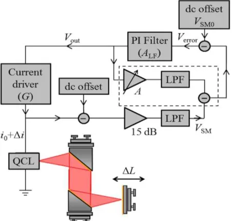
A schematic diagram of our system is shown in Fig 1. The THz QCL consisted of a 10-µm-thick bound-to-continuum active region [21], which was processed into a semi-insulating surface-plasmon ridge waveguide with dimensions 3 mm 140 µm. Measurements of the emission spectrum of the isolated laser, performed using a Fourier-transform infrared spectrometer with a spectral resolution of 7.5 GHz, revealed emission in a single longitudinal mode at a frequency, ~2.62 THz
The mirror position was recorded in real-time at a sampling rate of 10 kS/s through the analogue output of the stage encoder. An externally modulated current source was used to drive the laser with an electronically-conditioned dynamic feedback current superimposed on a quiescent current of 1080 mA (=1.08 ). The SM signal ( ) was monitored using the QCL terminal voltage, which was amplified using a 15 dB dc-coupled voltage amplifier following subtraction of a dc voltage offset.
Fig. 1. Schematic diagram of the experimental system. A control signal is generated by a PI loop filter (transfer function ) acting on the self-mixing voltage . The current driver (transconductance ) causes a corresponding perturbation to the QCL driving current , leading to active phase-nulling of . The dashed box indicates the compensation loop used to cancel voltage modulation of the laser. LPF low pass filter.
Under constant current operation (i.e. without electronic feedback control) the laser under OF experiences a perturbation to the laser terminal voltage, producing a series of fringes described by the equation
cos , in which is the modulation index and is the external round-trip phase given by , with being the emission frequency under OF and c the speed of light in vacuum [22]. It follows that the phase change arising from a change in external cavity length can be compensated by an electronic feedback loop acting on the QCL emission frequency [13]. In this case the condition holds, enabling an expression for the corresponding tuning of the emission frequency to be obtained. For small perturbations this can be expressed as
(1)
In our active phase-nulling scheme, the amplified SM signal was conditioned into an appropriate feedback control signal using an adjustable proportionalintegral (PI) loop filter. A dc offset stage at the input to this filter enabled precision control of the fringe locking position
, such that the error signal
under appropriate feedback control. The local slope of the SM fringe around this locking position determines the optimum loop parameters for feedback control, with the fringe shape itself being dependent in particular upon the feedback parameter [3], which was determined to be C ~ 0.25 in our case. However, it is anticipated that this scheme would also operate under moderate feedback (C>1) [14]. The transfer function of the PI filter, , was tuned empirically to provide 0 dB of proportional gain for frequencies 1 kHz, and integral gain with a slope 10 dB/decade below this corner frequency. The filter output, was fed into the modulation input of the current driver to control dynamically the driving current. The resulting current perturbation is given by
, in which 200 mA/V is the transconductance of the current driver across its 65 kHz bandwidth. The corresponding change in emission frequency of the QCL under electronic feedback can therefore be expressed as
(2) where k is the frequency tuning rate of the QCL. In addition to this frequency tuning effect, the applied current perturbation also causes a direct modulation of the QCL terminal voltage through the differential resistance of the device, R. For small perturbations around the operating point of the laser, R can be approximated as being constant. This unwanted component of voltage modulation can therefore be subtracted from the input to the loop filter by use of an adjustable inverting amplifier stage acting on the filter output , as shown by the dashed box in Fig. 1. This compensation loop was tuned to provide the necessary amplification, , by applying a 30 mA ramp modulation to the driving current of the laser without OF, and adjusting the amplifier such that its output matched the resulting modulation of the QCL voltage.
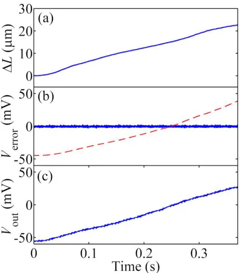
Figure 2(b) shows the error signal obtained in response to a modulation of the external cavity length, without feedback control of the QCL. In this example the cavity length was increased at a rate of ~60 m/s with a peak mirror displacement ~ 25 m (corresponding to approximately half a fringe), as shown in Fig. 2(a). As expected, under open-loop operation the SM signal (and hence ) varies according to the external round-trip phase , as described above. By contrast Fig. 2(b) also shows obtained in the closed-loop condition, along with the corresponding control signal (Fig. 2 (c)). In this case the SM voltage is maintained at a constant value as the feedback loop acts to compensate for the varying round-trip phase by dynamic control of the laser emission frequency. The resulting time-dependent frequency excursion of the laser can be deduced from the recorded mirror trajectory by use of Eq. 1. By correlating this with the measured control signal, the frequency tuning can be mapped as a function of current perturbation , enabling the tuning rate k to be determined using Eq. 2. The relationship between and obtained in this way is shown in Fig. 3. From a linear fit to this data a value k = −8.2 MHz/mA is found,
Fig. 2. (a) Change in cavity length . (b) Corresponding error signal measured without (red, dashed) and with (blue, solid) electronic feedback control of the QCL. (c) Corresponding feedback control signal generated by the PI filter.
To validate further our technique, the tuning rate was also measured using an alternative, non-real-time method based on that described in Ref 10. Briefly, this swept-frequency interferometric method employs a linear frequency modulation of the QCL under OF, thereby generating a series of SM fringes on the terminal voltage. By tracking the phase of these fringes over a series of known cavity lengths, the relationship between driving current and the corresponding frequency tuning of the laser can be obtained in an analogous fashion to that reported here. The results of this analysis are shown in the inset to Fig. 3, for which a value k = −8.5 MHz/mA is obtained, in good agreement with the value measured using our real-time electronic feedback approach.
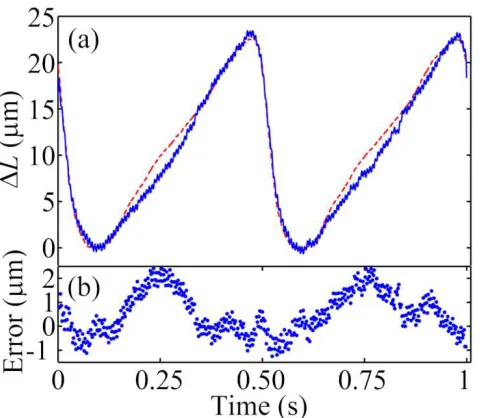
[image:4.612.313.552.51.241.2]As a second demonstration of our scheme we have applied it to the reciprocal modality, namely the real-time displacement sensing of targets. In this case the filter output generated in response to a moving target represents a replica of the target displacement, scaled by the responsivity factor = 3.9 V/mm according to Eq. 1 and 2, and using the value k = −8.2 MHz/mA. Figure 4(a) shows the displacement measured over two oscillation cycles of a mirror vibrating at 2 Hz with a peak-to-peak displacement, D = 22.5 m. This SM measurement yields a value of D = 23.1 m, representing an error of only ~2.5%. From Fourier analysis of the filter output signal, the noise equivalent displacement was found to be ~0.2 m for a 1 Hz measurement bandwidth centered around the oscillation frequency of 2 Hz. In addition, the maximum displacement error recorded over the full range of displacement was determined to be ~2.5 m (see Fig. 4(b)). We attribute this displacement error primarily
Fig. 3. Frequency tuning of the QCL arising from a current perturbation , as determined from the feedback control signal measured in response to a modulation of the external cavity length. A linear fit to the data (red, dashed line) yields a tuning rate k = −8.2 MHz/mA. Inset: Relationship between driving current and determined using a swept-frequency interferometric measurement (blue circles). A linear fit to this data (red, solid line) yields a tuning rate k= −8.5 MHz/mA.
to the voltage-dependent differential resistance of the device causing incomplete subtraction of the laser voltage modulation by the compensation loop. This same effect also determines the practical current modulation amplitude to be ~30 mA in our system, which corresponds to a measurable displacement amplitude of ~40 m. It is worth emphasizing, though, that with correct non-linear compensation of the QCL voltage modulation (using a digital synthesizer, for example), the useful current modulation range could be extended up to the mode-hop free tuning range of the laser under OF, which is ~100 mA in our case. Furthermore, the operating range of the electronic feedback loop in our system is expected to be = 3.6 cm [13] for an open-loop gain
= 630, suggesting much greater displacement amplitudes could, in principle, be measured using our technique.
[image:4.612.56.293.52.320.2]Fig. 4. (a) Displacement (blue, solid line) determined from the feedback control signal , in response to two oscillation cycles of a target vibrating at 2 Hz with a peak-to-peak displacement of 22.5 m (actual displacement shown by the red, dashed line). (b) Displacement error determined from the difference between the measured and actual displacements.
loop filter bandwidth. This same approach could equally be applied to the surface profiling of targets; in this case the output voltage would portray the surface morphology as the target is scanned laterally through the focussed beam. Finally, we note that the electronic feedback approach reported here would also be applicable to frequency-stabilisation schemes for THz QCLs, for which frequency drifts can occur on the scale of several MHz (~ 1 part in 105−106) over time-scales of seconds [15, 17, 24].
For example, according to Eq. 1, frequency stabilisation to 1 part in 107 would be possible using our scheme with a
10 m external cavity stable to within 1 m.
The authors acknowledge support from the EPSRC (UK), the ERC programme “TOSCA”, the Royal Society and the Wolfson Foundation, and the European Cooperation in Science and Technology (COST) Action BM1205. This research was supported under Australian Research Council's Discovery Projects funding scheme (DP 120 103703). Y.L.L. acknowledges support under the Queensland Government's Smart Futures Fellowships programme.
References
1. S. Donati, Laser & Photon. Rev. 6, 397−417 (2012) 2. R. Kohler, A. Tredicucci, F. Beltram, H.E. Beere,
E.H. Linfield, A.G. Davies, D.A. Ritchie, R.C. Iotti, and F. Rossi, Nature , 156−159 (2002)
3. S. Donati, Electro−Optical Instrumentation: Sensing and Measuring with Lasers, (Prentice Hall, New Jersey, 2004) 4. Y.L. Lim, P. Dean, M. Nikolić, R. Kliese, S.P. Khanna, M. Lachab, A. Valavanis, D. Indjin, Z. Ikonić, P. Harrison, E.H. Linfield, A. Giles Davies, S.J. Wilson, and A.D. Rakić, Appl. Phys. Lett. , 081108 (2011)
5. A. Valavanis, P. Dean, L. Yah Leng, R. Alhathlool, M. Nikolic, R. Kliese, S.P. Khanna, D. Indjin, S.J. Wilson, A.D. Rakic, E.H. Linfield, and G. Davies, IEEE Sensors Journal , 37−43 (2013)
6. P. Dean, Y.L. Lim, A. Valavanis, R. Kliese, M. Nikolić, S.P. Khanna, M. Lachab, D. Indjin, Z. Ikonić, P. Harrison,
A.D. Rakić, E.H. Linfield, and A.G. Davies, Opt. Lett. , 2587−2589 (2011)
7. F.P. Mezzapesa, L.L. Columbo, M. Brambilla, M. Dabbicco, M.S. Vitiello, and G. Scamarcio, Appl. Phys. Lett. 104, 041112 (2014)
8. P. Dean, A. Valavanis, J. Keeley, K. Bertling, Y. Leng Lim, R. Alhathlool, S. Chowdhury, T. Taimre, L.H. Li, D. Indjin, S.J. Wilson, A.D. Rakić, E.H. Linfield, and A. Giles Davies, Appl. Phys. Lett. 103, 181112 (2013) 9. Y.L. Lim, T. Taimre, K. Bertling, P. Dean, D. Indjin,
A. Valavanis, S.P. Khanna, M. Lachab, H. Schaider, T.W. Prow, H. Peter Soyer, S.J. Wilson, E.H. Linfield, A.G. Davies, and A.D. Rakić, Biomed. Opt. Express 5, 3981−3989 (2014)
10. A.D. Rakic, T. Taimre, K. Bertling, Y.L. Lim, P. Dean, D. Indjin, Z. Ikonić, P. Harrison, A. Valavanis, S.P. Khanna, M. Lachab, S.J. Wilson, E.H. Linfield, and A.G. Davies, Opt. Express , 22194−22205 (2013) 11. R.P. Green, J.−H. Xu, L. Mahler, A. Tredicucci,
F. Beltram, G. Giuliani, H.E. Beere, and D.A. Ritchie,
Appl. Phys. Lett. , 071106 (2008)
12. F.P. Mezzapesa, L.L. Columbo, M. Brambilla, M. Dabbicco, S. Borri, M.S. Vitiello, H.E. Beere, D.A. Ritchie, and G. Scamarcio, Opt. Express , 13748−13757 (2013)
13. S. Donati, M. Norgia, and G. Giuliani, Appl. Opt. , 7264−7268 (2006)
14. G. Giuliani, S. Bozzi-Pietra, and S. Donati, Meas. Sci. Technol. , 24 (2003)
15. S. Barbieri, J. Alton, H.E. Beere, E.H. Linfield, D.A. Ritchie, S. Withington, G. Scalari, L. Ajili, and J. Faist, Opt. Lett. , 1632−1634 (2004)
16. J.M. Hensley, J. Montoya, M.G. Allen, J. Xu, L. Mahler, A. Tredicucci, H.E. Beere, and D.A. Ritchie, Opt. Express
, 20476−20483 (2009)
17. A. Barkan, F.K. Tittel, D.M. Mittleman, R. Dengler, P.H. Siegel, G. Scalari, L. Ajili, J. Faist, H.E. Beere, E.H. Linfield, A.G. Davies, and D.A. Ritchie, Opt. Lett. , 575−577 (2004)
18. N. Beverini, G. Carelli, A. De Michele, A. Moretti, L. Mahler, A. Tredicucci, H.E. Beere, and D.A. Ritchie,
IEEE Trans. Instrum. Meas., , 262−265 (2007)
19. S. Donati, G. Giuliani, and S. Merlo, IEEE J. Quant. Elec.
, 113−119 (1995)
20. S. Donati and S. Merlo, J. Opt. , 156 (1998)
21. S. Barbieri, J. Alton, H.E. Beere, J. Fowler, E.H. Linfield, and D.A. Ritchie, Appl. Phys. Lett. , 1674−1676 (2004) 22. K. Petermann, Laser diode modulation and noise, 3rd ed.,
(Kluwer Academic, Dordrecht, 1991)
23. M.S. Vitiello, and A. Tredicucci, IEEE Transactions on THz science and technology 1, 76−84 (2011)
[image:5.612.53.294.53.262.2]