DESIGN OF PRECODING AND EQUALIZATION FOR
BROADBAND MIMO TRANSMISSION
Chi Hieu Ta and Stephan Weiss
Communications Research Group, School of Electronics and Computer Science University of Southampton, Southampton SO17 1BJ, UK
Keywords: Precoding, equalization, broadband MIMO.
Abstract
We propose a new approach to broadband MIMO precoding and equalisation by the use of a broadband singular value de-composition to decouple the MIMO system matrix into inde-pendent subchannels. In a second step, ISI present in the sub-channels is eliminated using methods developed for SISO sys-tems. A numerical example is given.
1 Introduction
Multi-input multi-output (MIMO) systems have attracted much attention recently due to their promise to significantly improve the channel capacity and the link reliability [1]. The key rea-son for this fact is that in MIMO systems aimed at capacity increases, multiple data streams or signals can be transmitted over the channel simultaneously, which is often referred to as spatial multiplexing.
In order to exploit a MIMO system for transmission with increased capacity, one must eliminate co-channel interference (CCI) between independent data streams as well as eliminate inter-symbol interference (ISI) in case of a frequency selective channel. A considerable amount of research has focussed on the narrowband case, where e.g. [5] has shown that joint pre-coder and equaliser design can achieve much if deployed on their own, provided that the channel state information (CSI) can be made available to both sides of the transmission link. In the narrowband case the channel matrix can be diagonalised by means of mostly SVD-based operations.
The demand of high transmission rate, however, requires the use of broadband systems which are affected by frequency selective channels, i.e. the link between any receiver and trans-mitter antenna pair is characterised by an impulse response. Therefore, broadband MIMO systems, in which each sub chan-nel between transmit and receive antennas is considered as a frequency selective fading channel, has drawn great interest of researchers. A method that is often used to remove CCI and ISI in broadband MIMO systems is to introduce redundancy to the data streams. In [8] and [7] optimal solutions to the joint precoder- equalizer design problem for block transmission over single input single output (SISO) frequency selective channels are discussed. The optimality criteria considered are the zero forcing (ZF) and minimum mean square error (MMSE) crite-ria [8] and the maximization of mutual information [7].
Solu-tions in [8] and [7] are then extended for the MIMO case in [9]. Palomar et al. [3] generalize the results on joint design of linear precoding-equalization to several criteria, classified into Schur-concave and Schur-convex objective functions. In general, there the equalizer matrix is derived as MMSE filter and the precoder matrix is determined through the SVD of the whitened channel.
In this paper, we propose a method for precoding and equal-ization for point-to-point broadband MIMO channels. Differ-ent from block transmission, we utilise in a first step a recDiffer-ently proposed broadband singular value decomposition (BSVD) to eliminate CCI. In a second step, the decoupled SISO channels are precoded and equalised using standard methods such as in [8].
The paper is organised as follows. In Sec. 2, the overall channel and system setup are laid out. Sec. 3 addresses the first step in the proposed design, aiming at CCI cancellation, while Sec. 4 considers the minimisation of ISI. Finally, a numerical example is provided in Sec. 5, while conclusions are drawn in Sec. 6.
In our notation, we use lower- and uppercase boldface font for vector and matrix quantities, respectively. Vector quanti-ties in the z-domain are also denoted as underline variables, e.g.X(z). The operator{·}˜ denotes the parahermitian trans-pose, i.e.A(˜ z) =AH(z−1).
2 Channel Model and System Setup
2.1 Spatio-Temporal MIMO System Matrix
In the following, we assumed a stationary MIMO channel with transfer functionC(z)∈CR×T(z), such that
C(z) =
L−1
X
l=0
C[l]z−l (1)
MIMO matrix, by appropriate ordering ofS(z)andR(z), takes the block-pseudo-circulant form
H(z) =
C0(z) z−1CP−1(z) · · · z−1C1(z)
C1(z) C0(z) · · · z−1C2(z)
..
. . .. ...
CP−1(z) CP−2(z) · · · C0(z)
. (2)
The matricesCp(z),p= 0,1, . . . P −1, are theP polyphase
components ofC(z)such that
C(z) =
P−1
X
p=0
Cp(zP)z−p (3)
or alternativelyCp(z) =PnC[nP+p]z−n.
[image:2.612.318.552.101.294.2]2.2 Precoder and Equaliser
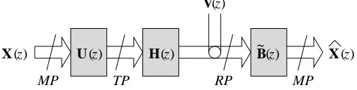
Fig. 1 indicates the positions of a precoderU(z)∈CP T×P M and an equaliserB(˜ z)∈ CP M×P R in the transmitter and re-ceiver, respectively, wherebyM ≤ min{T, R}. As hinted in Sec. 1, the aim ofU(z)andB(˜ z)is to diagonaliseH(z), thus eliminating CCI, and to reduce each polynomial on the main diagonal to a scalar element in order to suppress ISI.
In [5], a narrowband system with P = 1 and H(z) = C[0] = constantis addressed. There, the precoder and equaliser are not of polynomial form and can be calculated by singular value decomposition (SVD) ofC[0], or a sequence of SVDs in case the received signals cannot be jointly processed, resulting in a diagonalised system that therefore avoids CCI but does not impose ISI because of its narrowband nature.
In a broadband scenario forP = 1, theH(z) = C(z)is anR×T polynomial matrix of orderL−1. As the number of polyphase components P is increased, the matrix size in-creases, but the polynomial order reduces in accordance with the shortening polyphase responses. OnceP =Lis reached, the polyphase componentsCp(z)are constants with no
depen-dency onz. However, the block-pseudo-circulant form of (2) means for allP > L, the spatio-temporal MIMO system ma-trixH(z)will be a first order polynomial.
In order to overcome the polynomial order, the block-trans-mission based systems in [8] for T = R = 1and in [9] for arbitraryTandRrely on a time multiplex that is chosen longer than the channel support, i.e. P = M +L. As a result, the matrixH(z)in (2) is a sparse block-pseudo-circulant matrix of
)
U (z) B(z)
V(z)
X (z) X (z)
RP TP
MP MP
H(z ~
Fig. 1. MIMO channelH(z)with precoderU(z)and equaliser ˜
B(z).
only first order inz, as noted earlier. Specifically,
H(z) = H0+z−1H1 with (4)
H0 =
C0 0 . . . 0
.. . . .. CL−1 C0
. .. . .. 0 0 CL−1 . . . C0
(5)
H1 =
0 . . . 0 CL−1 . . . C1
. .. ... ..
. CL−1
..
. 0
.. .
0 · · · 0
(6)
Since terms withz−1 are only located in the upper right
tri-angle, two methods can be chosen to eliminate the polynomial order of the MIMO system matrix by suppressingH1such that
only a part ofH0in (5) is utilised: (i) transmittingL−1
lead-ing zeros inS(z), or (ii) discarding the firstL−1 inR(z). Thus eliminating the polynomial nature ofH(z), the precoder and equaliser systems can be selected as non-polynomial ma-trices whose design can be accomplished using standard linear algebraic methods.
2.3 Proposed Design
The approach to MIMO precoding and equalisation proposed in this paper is based on a broadband singular value decompo-sition (BSVD) ofH(z)as proposed in [2, 6], such that
H(z) =B(z)
Σ(z) 0 0 0
˜
U(z) (7)
wherebyΣ(z) =diag{Σ0(z),Σ1(z),· · ·ΣP M(z)}. This
per-mits to take the polynomial nature of the MIMO channel trans-fer function into account without resorting to block transmis-sion, giving greater flexibility in the choice ofMand hence the code rate and subsequently the coding gain. However, the di-agonalisation according to (7) only eliminates CCI, while each of theP Msubchannels is dispersive and causes ISI.
To cancel ISI, in a second step a precoder and equaliser can be designed for each subchannel, e.g. according to the SISO design discussed in [8]. Thus, block transmission is invoked, but only for small portion of the system design. In addition, the precoder and equaliser design can take the individual properties of each subchannel, such as the SNR, into account.
3 MIMO System Decomposition Via BSVD
3.1 Broadband Singular Value Decomposition
[image:2.612.41.293.654.718.2]BSVD can be obtained via two broadband eigenvalue decom-positions, whereby a parahermitian matrixR1(z) =H(z) ˜H(z)
is decomposed such that
R1(z) =B(z)Γ1(z) ˜B(z) . (8)
Besides the diagonality of Γ1(z) = Σ(z) ˜Σ(z), we demand
paraunitarity ofB(z)such thatB(z) ˜B(z) = ˜B(z)B(z) = I and spectral majorisation ofΓ1(z)[11] such that the diagonal
elements of
Γ1(z) =diag{Γ0(z), Γ1(z), . . . ΓK−1(z)} (9)
are ordered according to
Γk(ejΩ)≥Γk+1(ejΩ) ∀Ω and k= 0,1, . . . , K−2,
(10) similar to the ranking of the singular values in a singular value decomposition. Note that paraunitarity or losslessness ofB(z) conserves power, i.e. tr{Γ1(z)}|z=0=tr{R1(z)}|z=0.
In a similar operation,U(z)can be obtained via broadband EVD ofR2(z) = ˜H(z)H(z).
3.2 Sequential Best Rotation Algorithm
In order to achieve the factorisation in (8) fulfilling spectral ma-jorisation according to (10), we use the second order sequential best rotation (SBR2) algorithm [2, 6], whose steps we briefly review below.
SBR2 is an iterative broadband eigenvalue decomposition technique based on second order statistics only and can be seen as a generalisation of the Jacobi algorithm. The decomposition afterLiterations is based on a paraunitary matrixBL(z),
BL(z) = L
Y
i=0
QiΛi(z) (11)
wherebyQiis a Givens rotation and the matrixΛi(z)a
parau-nitary matrix of the form
Λi(z) =I−viviH+z−∆iviviH (12)
withvi = [0 · · ·0 1 0 · · · 0]Hcontaining zeros except for a
unit element in theδith position. ThusΛi(z)is an identity
ma-trix with theδith diagonal element replaced by a delayz−∆i.
At theith step, SBR2 will eliminate the largest off-diagonal element of the matrixB˜i−1(z)R1(z)Bi−1(z), which is defined
by the two corresponding sub-channels and by a specific lag index. By delaying the two contributing sub-channels appro-priately with respect to each other by selecting the positionδi
and the delay ∆i, the lag value is compensated. Thereafter
a Givens rotationQi can eliminate the targetted element such
that the resulting two terms on the main diagonal are ordered in size, leading to a diagonalisation and at the same time accom-plishing a spectral majorisation.
Hence, each step comprises of optimising the parameter set{δi, ∆i, θi}. While the largest off-diagonal element in
˜
Bi−1(z)R1(z)Bi−1(z)is eliminated, the remainder of the
ma-trix is also affected. In extensive simulations, SBR2 has proven
very robust and stable in achieving both a diagonalisation and spectral majorisation of any given covariance matrix, whereby the algorithm is stopped either after reaching a certain measure for suppressing off-diagonal terms or after exceeding a speci-fied number of iteration [2, 6].
3.3 Precoder and Equaliser for CCI Suppression
The algorithm outlined above in Sec. 3.2 provides a factori-sationS(z) = ˜BL(z)H(z)UL(z), wherebyS(z)is
approxi-mately diagonalised, such thatUL(z) can be employed as a
precoder andB˜L(z)as an equaliser as shown in Fig. 1. Due to
the decoupling, we can treat the resulting MIMO systemS(z) as a system of separate subchannels. Due to spectral majori-sation, the gain of the subchannels, and therefore their SNR, will drop with rising subchannel index. In the following we characterise this subchannel SNR.
Let SNRi be the SNR of the ith subchannel, Sij(z)the
element ofS(z) placed in the ith row and jth column, and
Sij(ejΩ)its evaluation on the unit circle z = ejΩ. Further,
Rxi,xi(z)is the power spectral density of theith input inX(z), which we assume to be mutually uncorrelated with all other in-puts. Then power spectral density of the signal component in theith channel,Ri(z), is given by
Ri(z) =Sii(z)Rxi,xi(z) ˜Sii(z) . (13)
The remaining CCI components can be characterised by the CCI power spectral densityRi,CCI(z),
Ri,CCI(z) =
X
j,j6=i
Sij(z)Rxj,xj(z) ˜Sij(z) . (14)
The channel noise appears in the outputXˆ(z)filtered by the equaliserBL(z), such that is power spectral matrix at the
out-putRee(z) =BL(z)Rvv(z) ˜BL(z). If the noise power
spec-tral densityRvv(z) =σvv2 I, then due to paraunitarity ofBL(z),
Ree(z) =σvv2 I. Therefore, we obtain
SNRi=
1 2π
2π
Z
0
Ri(ejΩ)
Ri,CCI(ejΩ) +σvv2
dΩ (15)
The SNR value in (15) permits decisions on which sub-channels are suitable for transmission, for example by means of waterfilling under the constraint of a given transmit power [4]. However, the problem of ISI within the selected subchannels remains, and will be addressed next.
4 SISO Subchannel Precoding and Equalisation
i opt F s p s p Gopti
[image:4.612.44.286.78.212.2]p s p s z ) ( i M P P M ) (z ii S (z ) Y Y i i i i i i (z ) V
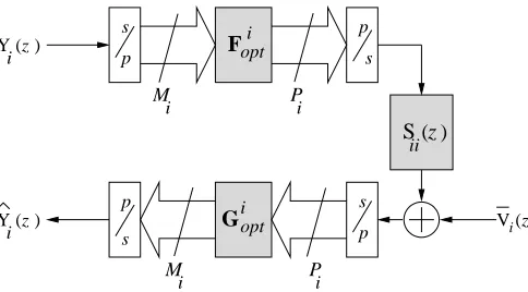
Fig. 2. Joint precoding and equalization for frequency selective SISO channel.
Our explanations are based on the precoding and equali-sation architecture provided in Fig. 2, which only shows the arrangement for theith subchannel. We defineRyiyias the co-variance matrix of the input signalYi(z)andRv¯iv¯ias the noise covariance matrix arising from the signalV¯i(z). Note that the
latter comprises of the channel noise filtered byB(˜ z)and the CCI components of theith channel characterised in (14), such that at the input of the equaliser Gi
opt we measure the SNR
stated in (15). Further, the Toeplitz matrix S(i) contains the
impulse response of length Li of the ith subchannel, Sii(z),
produced by the BSVD in Sec. 3.3,
S(i) =
s(i)[0] 0 . . . 0
..
. . .. ... ...
s(i)[L
i−1] . .. 0
0 . .. s(i)[0]
..
. . .. . .. ... 0 . . . 0 s(i)[Li−1]
(16)
wherebySii(z) =P Li−1
n=0 s
(i)[n]z−n. The use of a single time
slice as opposed to the analysis in (4) stems from the block based transmission avoiding inter-block interference by means of eitherLi leading zeros or Li discarded symbols at the
re-ceiver, thus requiringPi ≥Mi+Li. Based onRyiyi,R¯viv¯i, andS(i), we define the following EVD factorisations:
Ryiyi = Wi∆iW
H
i
SH(i)R−v¯i1¯viS(i) = ViΛiVi (17)
with the diagonal matrices
∆i = diag
n
δ00(i), δ11(i), · · · δM(i)
i−1,Mi−1
o
(18)
Λi = diag
n
λ00(i), λ11(i), · · · λ(Mi)
i−1,Mi−1
o
(19)
The method outline in [8] proposes the design ofGi
optand
Fi
opt under two criteria, either maximising the output SNR
(max-SNR) or minimising the mean-square error under
con-strained transmit power (MMSE/CP). In the first case, the max-SNR optimum filter bank pair is given by
Fiopt =
√
K σv¯i
ViΛ
−1 2
i (20)
Giopt = σv¯i
√
KΛ−12VH
i S
H (i)R
−1 ¯
viv¯i (21) whereK is gain in the transmitter. The MMSE/CP optimum filter bank pair is given by
Fiopt = ViΦiWHi (22)
Giopt = Ryiyi(F
i
opt)HSH(i)
Rv¯iv¯i+S(i)F
i
optRyiyi(F
i
opt)HSH(i)
(23)
whereΦiis diagonal with elements given by
|φ(jji)|2= Pi+tr
Λ−i 1 trnΛ−12
i ∆ 1 2 i o 1 q
λ(jji)δjj(i)
− 1
λ(jji)δ(jji) (24)
in order to enforce the constraining of the transmit power of the
ith subchannel toPi[8].
5 Simulations and Results
5.1 Simulation
In this section, we illustrate the proposed approach by means of a numerical example. We assume a4×4broadband MIMO channel whose temporal responses are generated from a Saleh-Valenzuela indoor channel model [10]. The resulting MIMO channel length isL= 5.
The diagonalisation and spectral majorisation ofH(z)leads to 4 subchannels with frequency responses ordered in descend-ing value, as shown in Fig. 3. It is clear that of the 4 sub-channels, only the first three offer a reasonable channel gain and therefore sufficient quality for transmission, thus setting
M = 3or potentially lower.
For each subchannel, a precoder and equaliser is computed according to Sec. 4. With subchannel lengths ofLi∈ {56; 63}
andi= 0, 1,· · · M−1, a block size ofMi= 32is employed
for allM systems for simplicity. In order to assess the result of the design process, we measure the BER in terms of an SNR figure suggested in [8], which sets the afforded transmit power against the channel noise measured at the SISO receiver. Thus, in this case CCI is considered as a channel noise component, such that for theith subchannel
SNR = tr
Fiopt(Fiopt)H
Rσ2 ¯
vi
. (25)
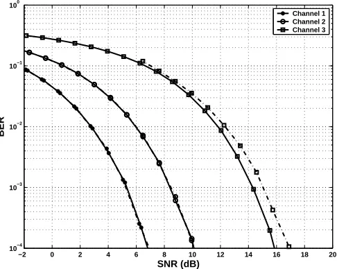
It can clearly be noted from Fig. 4 that the three selected channels offer a degrading BER performance with rising sub-channel index.
−0.5 −0.4 −0.3 −0.2 −0.1 0 0.1 0.2 0.3 0.4 0.5 −40
−30 −20 −10 0 10 20
Normalized angular frequency Ω/2π
|S
ii
(e
i
Ω)| (dB)
S11(e
iΩ)
[image:5.612.48.287.81.272.2]S22(eiΩ) S33(eiΩ) S44(eiΩ)
Fig. 3. Frequency responsesSii(ejΩ)of subchannels after
di-agonalisation ofH(z).
6 Conclusion
We have discussed a design of precoders and equalisers for broadband MIMO systems which are based on two separate steps. First, the CCI imposed by the MIMO transmission sys-tem is suppressed by means of a BSVD, similar to how a stan-dard SVD would be employed for a narrowband MIMO chan-nel. Second, SISO precoding and equalisation techniques are invoked in order to mitigate ISI within the subchannels.
The proposed scheme differs from other works, e.g. [8, 9], in the absence of a block transmission scheme for the first step, i.e. the CCI cancellation. The use of the SBR2 algorithm to accomplish a BSVD has some pitfalls since it allows little con-trol over the filter order that is obtained for the diagonalised system and therefore the decoupled subchannels. Note how-ever that in Fig. 3 the the first two subchannels exhibit only very low spectral dynamics and would therefore only require an equaliser (and precoder) of relatively small order. There-fore, future work will attempt to further exploit the potentials of this approach.
Acknowledgements
The research of Chi Hieu Ta is supported by a scholarship from the Vietnamese Ministry of Education and Training.
References
[1] A. Goldsmith, S. A. Jafar, N. Jindal, and S. Vishwanath. Capacity Limits of MIMO Channels. IEEE JSA, 21(5): , 2003.
[2] J. G. McWhirter and P. D. Baxter. A Novel Technqiue for Broadband SVD. In Workshop Adaptive Sensor Array
Proc., Cambridge, MA, 2004.
−2 0 2 4 6 8 10 12 14 16 18 20
10−4 10−3 10−2 10−1 100
SNR (dB)
BER
Channel 1 Channel 2 Channel 3
Fig. 4. BER versus SNR for the subchannelsSii(ejΩ),i =
0,1,2after SISO precoding and equalisation according to [8].
[3] D. P. Palomar, J. M. Cioffi, and M. A. Lagunas. Joint Tx-Rx Beamforming Design for Multicarrier MIMO Chan-nels: A Unified Framework for Convex Optimization.
IEEE Trans SP, 51(9):2381–2401, 2003.
[4] D. P. Palomar and J. R. Fonollosa. Practical Algorithms for a Family of Waterfilling Solutions. IEEE Trans SP, 53(2):686–695, 2005.
[5] C. Peel, Q. Spencer, A. L. Swindlehurst, and B. Hochwald. Downlink Transmit Beamforming in Multi-User MIMO Systems. In IEEE Workshop
Sen-sor Array and Multichannel Signal Proc., vol. 1, Sitges,
Spain, 2004.
[6] S. Redif and T. Cooper. Paraunitary Filter Bank Design via a Polynomial Singular Value Decomposition. In Proc.
IEEE ICASSP, 4: 613–616, Philadelphia, PA, 2005.
[7] A. Scaglione, G. B. Giannakis, and S. Barbarossa. Filter-bank Transceivers Optimizing Information Rate in Block Transmission over Dispersive Channels. IEEE Trans Inf. Theory, 45(4):1019–1032, 1999.
[8] A. Scaglione, G. B. Giannakis, and S. Barbarossa. Redun-dant Filterbank Precoders and Equalizers. I. Unification and Optimal Designs. IEEE Trans SP, 47(7):1988–2006, 1999.
[9] A. Scaglione, P. Stoica, S. Barbarossa, G. B. Giannakis, and H. Sampath. Optimal Designs for Space-Time Linear Precoders and Decoders. IEEE Trans SP, 50(5):1051– 1064, 2002.
[10] A.A.M Saleh and R.A. Valenzuela. A Statistical Model for Indoor Multipath Propagation. IEEE JSAC, 5(2):128– 137, 1997.
[image:5.612.308.551.83.277.2]