Imprecise Synthesis
Bill Mitchell
Department of Computing, University of Surrey
Guilford, Surrey GU2 7XH, UK
Robert Thomson, Paul Bristow
Motorola UK Research Lab, RG22 4PD, UK
{brt007, paul.c.bristow}@motorola.comAbstract
Around a third of significant faults in embedded systems are caused by defective requirements specifications. Inds-trial case studies using existing techniques to construct ana-lytical requirements models have been frustrated because of imprecise compositional semantics in the industrial specifi-cations. The paper describes a method for synthesising an-alytical models from imprecise MSC requirements specifi-cations that ensures the models reflect the intended compo-sitions, and not those that result from the imprecision within the requirements.
1. Introduction
Scenario based specifications are common in telecom-munications and automotive concurrent embedded systems. Many of these scenarios are described as Message Se-quence Charts (MSCs). MSC is mandated by standards bod-ies such as the ITU and ETSI [4] for defining scenarios within standards. MSC 2000 [13] is currently being incor-porated within UML 2.0. Studies have shown that around 30% of faults in embedded systems are caused by errors and omissions of requirements specifications [12]. Hence the study of analytical models for MSC based specifications is a worthwhile exercise.
The paper describes a method for synthesizing require-ments MSC specifications into a particular type of finite state machine that characterises permissible compositions of the requirements scenarios. The method was formulated from an industrial case study of around three hundred MSCs used within Motorola to define TETRA [11] requirements. Industrial MSC scenarios are commonly annotated with global state like information, which should make compo-sition straightforward. However, these states are often used imprecisely across different requirements scenarios. There-fore not all the compositions that result from treating the states as if they are precisely defined will be valid. We will refer to these state like constructs as phases.
Intuitively we regard a phase as a composite global state with imprecise compositional semantics. A composite state within a UML statechart can have several entry and exit states (as well as a start and stop state). Where a phase oc-curs in an MSC scenario it does not specify which entry or exit states are used. This makes composition based on state semantics ambiguous. When the same phase occurs in two MSCs it is not clear whether the entry and exit states of the two phase occurrences are the same. The case study showed that it is only safe to assume they are the same when the phase occurrences are reached in a consistent manner in both scenarios. The paper defines a phase semantics that for-malizes when two occurrences of a phase are consistently reached and define the same entry and exit states. The pa-per then defines a phase transition process that captures the valid compositions of process behaviours with respect to the phase semantics. The phase transition process is canonical up to a particular kind of simulation equivalence that re-spects phase transitions (Definition 6.1). This leads to a pro-cess algebra that generates the phase transition propro-cess from the MSC requirements, (Theorem 7.1). The phase transition process is always finite (Theorem 7.3) and can therefore be represented by a finite state machine.
There has been much work on the area of synthesising scenario based specifications into analytical models. Alur and Yannakakis [2] described a method for realizing MSC scenarios as processes that capture the implied behaviour of the specifications. Bontemps and Schobbens [7] have de-scribed methods for synthesising automata from Live Se-quence Charts (LSCs, [9]), and have used game theory [3] to automatically construct strategies for constructing programs from LSCs. Uchitel, Kramer and Magee [10] describe meth-ods to automatically construct UML statecharts from MSC scenarios that are annotated with state information.
stud-ies. The method described here has been implemented by Motorola UK Research Labs, and is being used in a pilot study for a new telecommunications mobile 3G handset.
The phase semantics is a weakening of the state seman-tics from [10], whilst permitting some additional semanseman-tics in the spirit of LSCs. The semantics here differs from that of LSCs in that mandatory behaviour is defined dynamically within the domain of possible scenarios. This permits a se-mantics which uses domain knowledge to define valid com-positions.
2. Partial Order Semantics for MSCs
An MSC defines a partial order semantics on the order that system events can be observed to occur. Such a par-tial order is referred to as the causal order of the MSC. The causal order restricts how events can occur within any trace of the system. The semantics are well known in the litera-ture ([1], [5], [13]), so we only provide a terse exposition here. For arbitrary MSCs that include iteration the set of traces generated by the MSC for the whole system is not al-ways regular [1], however the traces of each individual sys-tem process in an MSC are always regular which is suffi-cient for our purposes.
Let<be a causal order on a set of eventsE for some MSC. A messagem defines two events, a send event!m and a receive event?m. A causal ordering defines the par-tial order semantics for a set of concurrent events in an MSC scenario. For a setS⊆Edefine
n(S, <) = {x∈E| ∃y∈S: y < x, and ¬∃z∈E: y < z < x} m(S, <) = {x∈S | ¬∃y∈S: y < x}
af(a, S, <) = m((S− {a})∪n({a}, <), <)
The setaf(a, S, <)characterises how events may followa in an execution trace, whereSdescribes the set of all events that are eligible to occur concurrently witha. Suppose we have an execution tracetthat is a total extension of<. Let abe some event int, so thattis of the formt0·a·t1(where
·denotes concatenation). LetSbe the set of minimal events from the set of all events int1. Thent1must be of the form b·t2whereb∈af(a, S, <).
For a setS ⊆Erecursively define a process term onS from<by
Pr(S, <) = X {a∈S}
a·Pr(af(a, S, <), <)
andPr(∅, <) = 0.
For a partial order < on events E, the term Pr(m(E, <), <) defines the partial order semantic pro-cess for<. Given an MSCM, and its partial order seman-tics<M, letPr(M) = P(m(E, <M), <M). ThenPr(M)
defines the externally observable behaviour of the sys-tem defined byM. Similarly for an MSCM, for each pro-cessPinM we can extract the set of eventsE(P)that oc-cur inPand the causal ordering<P imposed byM on the
events inP. The processPr(P) = Pr(m(E(P), <P), <P)
then defines the observable behaviour of P in M. In [5] they define a particular type of asynchronous parallel com-position |A, together with a special traffic channel pro-cessT. Roughly the idea is that when a process transmits a send message !m it is stored by the traffic channel un-til the relevant process wishes to consume the receive mes-sage?m. Then T delivers the message.T is designed so that it acts rather like an unbounded buffer with random ac-cess.
One can prove [5] that whenMconsists of processesPi
for1 ≤i ≤n, thenPr(M)is strong bisimulation equiva-lent to
T |APr(P1)|APr(P2)|A· · · |APr(Pn)
In general it is also provable thatPr(S, <1)is strong bisim-ulation equivalent to Pr(S, <2) if and only if the set of traces of Pr(S, <1) are the same as Pr(S, <2). This is proved by showing that the set of traces of Pr(S, <) uniquely define<with respect toS.
We may therefore identify each process in an MSC first with a process algebra term defined by the causal ordering in the MSC, and second by a set of traces that are defined by that process.
Definition 2.1 DefineT(P)to be the set of traces gener-ated by the processPr(P).
The definition here for Pr(P) has to be extended for MSC scenarios that include alternatives, process creation, iteration and so on. For further details refer to [5].
3. Informal Compositional Semantics
Informally we can give requirements scenarios the fol-lowing semantics, which will allow us to construct phase transition processes from them. Suppose we have a scenario M that defines message exchanges between processes, in-cluding the processQ.
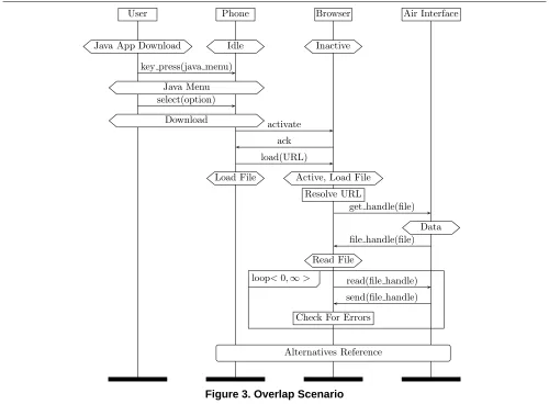
Consider figure 3, which is a requirements scenario for a wireless mobile handset. This describes how a WAP ‘Browser’ process downloads a Java application iteratively from the ‘Air Interface’ process until it receives the ‘EOF’ message, or it detects that the file is corrupted.
An eventxin an MSCM occurs in the scope of phase symboluif the first phase symbol prior toxwithin the pro-cess it belongs to isu. We refer to a phase thatxis in the scope of as an active phase forx.
Given a trace of events for a process, we can annotate each event with the phases that were active before and af-ter that event occurred. When these phases are different the event is called a phase transition event. Such an annotated trace is defined to be a phase trace, which we formally de-fine later (see definition 4.1). Consider two phase tracest1 andt2, wheret2is a suffix oft1and terminates with a phase transition. Hence we may writet1=t3·t2for somet3, and let the end event oft2be an eventethat causes a transition to some phasep. I.e.t2=t02·ewhere the phase prior toeis notp, and the phase aftereisp. In this case we will sayt1 andt2 match and thatpis reached consistently. Hence we can suppose the two occurrences ofprefer to the same en-try and exit states in both traces. This leads us to the idea of phase transition simulation between processes.
A processP simulates the phase transitions ofQwhen the following holds. If we observe a trace of annotated events ofP that leads to a phase transition, with some suf-fix equal to a phase trace ofQ, thenP must be able to sim-ulate the (annotated) behavior ofQfrom then on. We define this equivalence formally in Definition 6.1. Given a number of specification processesQiit is possible to define a
canon-ical process that simulates the phase transitions of them all as will be defined in section 7. This is the phase transition process mentioned in the introduction.
This informal semantics is similar to LSC semantics where a scenario can express some behaviour as universal, which must occur once a particular guard in the form of a prechart has been witnessed. That is if ever the system be-haviour matches the prechart part of the LSC it must then match the rest of the behaviour in the main chart. The differ-ence here is that when certain initial behaviour is matched then the subsequent phase symbol(s) take on state like mantics, which is similar to but not the same as the state se-mantics of [10].
Another difference is that an MSC is not explicitly di-vided into distinct sections consisting of prechart and main chart. IfP matches any initial behaviour leading to a tran-sition, then it matches all the remaining behaviour. Hence which parts of the scenario act like a prechart guard, and which like the main chart are determined dynamically. In section 5 we will define context semantics in order to in-clude some domain knowledge that allows matching to be applied consistently across large specification repositories.
4. Annotated Events
LetP be the set of phase symbols associated with an MSCM, and letψbe a map that defines the set of phase
User Phone Browser
Java App Download Idle Inactive
key press(java menu)
Java Menu
select(option)
Download
activate
ack
load(URL)
Load File Active
Download File
Download
download OK
[image:3.595.318.553.73.395.2]Inactive Display Notification
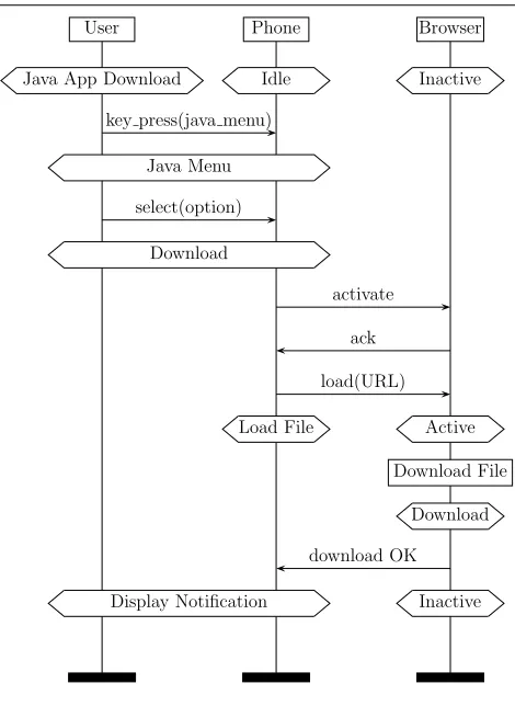
Figure 1. Java App Download Scenario
names for each symbol. I.e.ψ:P −→2Ph, wherePhis the
set of phase names.
Where E is the set of events for an MSC M, letφ : E−→Phbe the function that maps each eventeto the set of phases it belongs to, that is the setψ(u), whereeis in the scope ofu.
Definition 4.1 Define the phase traces for a processP in an MSC scenarioM to be sequences of triples:
(S0, e0, S1) (S1, e1, S2)· · ·(Sn, en, Sn+1) wheree0, . . . , enis an event trace ofP,Si⊆Ph,φ(ei) =
Si, andSn+1is the last phase for processPin the scenario M.
In figure 1 each process generates a single phase trace. For example the phase tracet0for the ‘Browser’ process is:
({Inactive}, ?activate, {Inactive})
({Inactive}, !ack, {Inactive})
({Inactive}, ?load(URL), {Active})
({Active}, Download File, {Download})
({Download}, !download OK, {Inactive})
Phone Browser Air Interface
Download Inactive Channel
load(URL)
Active
Resolve URL
get handle(file)
Data
file handle(file)
Read File
read(file handle)
send(file handle)
Check For Errors loop<0,∞>
[image:4.595.57.291.74.370.2]Alternatives Reference
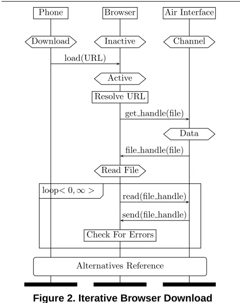
Figure 2. Iterative Browser Download
our aim is to provide a semantics that is a weakening of the state semantics, which will be suitable for more impre-cise specifications. Each triple in a phase trace is referred to as an annotated event.
5. Dynamic Constraints
Phase names found in industrial examples are not consis-tently chosen, nor is their meaning consistent across large sets of MSCs. It is therefore necessary to further compli-cate phase semantics by introducing a mechanism to relate phase names within a given context.
In order to relate phase names within scenarios we will treat them as if they are temporal boolean propositions, the moments where they are true define when the relevant phases are active. We will use a Hennessy Milner style of temporal logic to permit phases to act as a type of tempo-ral guard [8]. A tempotempo-ral modelT consists of a directed graphG, with vertex labellingν : GV −→ 2Ph, edge
la-bellingε:GE−→E, and some vertexithat represents the
initial moment. Temporal formulae are defined as usual:
• T, v²heiφiff there is an edge(v, w)∈GEsuch that
ε(v, w) =e, andT, w²φ
• T, v ² [e]φ iff for every edge (v, w) ∈ GE where
ε(v, w) =e,T, w²φ
• T, v² ¤φiffT, v²φandT, w² ¤φfor every edge (v, w)∈GE
• T, v² ♦φiff there is some vertexwreachable fromv such thatT, w²φ
The satisfiability of ordinary boolean formulae is defined as usual. Formulaφis satisfied inT whenT, i²φ.φis valid when it is satisfied in every model, when we write`φ. Definition 5.1 For a setS ⊆ Ph, defineVS = Vx∈Sx. For a phase tracet= (S, e, S0)·t0, define its temporal se-mantics as
ktk=^S∧ hei(^S0∧ kt0k)
A contextCis any temporal formulae overP andE. A temporal context controls how phases are related across the requirements scenarios.
Consider figure 2, which illustrates a scenario where a file is downloaded iteratively from the air interface by the WAP browser process. At each iteration the file is tested for errors. This example is based on a real requirements sce-nario used in one of the Motorola case studies. The rest of the scenario then continues in another MSC ‘Alternatives Reference’. Hence the file download will terminate either when an error is detected, or the ’EOF’ signal is received.
In this example suppose that if aload(URL)message is received then the‘Load File’phase is valid whenever Ac-tiveis valid. The context is then
¤([?load(URL)](Active⇒‘Load File’))
The temporal context permits phases defined by different development teams to be given a consistent meaning across scenarios without having to extensively rewrite the scenar-ios.
Definition 5.2 For context C we define phase trace t to match phase tracet0when
` C ⇒(ktk ⇒♦kt0k)
The matching formula is true when some suffix of the se-quencetcontains exactly the same event trace as the whole oft0, and the phase annotations of the corresponding events are logically consistent within the context defined byC. In-tuitivelytmatchest0 if after some initial delay,t0becomes the same astwithin the context defined byC.
Definition 5.3 Let a = (S, e, S0)be an annotated event. When6` C ⇒(VS⇒VS0)defineato be a phase transi-tion event.
Define a phase transition trace to be a trace of annotated events terminating with a phase transition event.
User Phone Browser Air Interface
Java App Download Idle Inactive
key press(java menu)
Java Menu select(option)
Download activate
ack load(URL)
Load File Active, Load File Resolve URL
get handle(file)
Data file handle(file)
Read File
read(file handle) send(file handle)
Check For Errors loop<0,∞>
[image:5.595.56.556.74.442.2]Alternatives Reference
Figure 3. Overlap Scenario
Lett1be the phase transition trace of the phase tracet0 consisting of
t1= ({Inactive}, ?activate, {Inactive}) ({Inactive}, !ack, {Inactive})
({Inactive}, ?load(URL),{Active})
In figure 2 the initial annotated event of process ‘Browser’ ist2=({Inactive},?load(URL),{Load File}). From this we can prove:
` ¤([load(URL)](Active⇒
‘LoadFile0))⇒(kt
1k ⇒♦kt2k) so thatt1matchest2.
6. Phase transition simulation
Given processes whose actions are annotated events we define first a simulation relation between them, and then a phase transition simulation relation. For annotated events a = (S, e, S0) andb = (U, g, U0)define a A
C b when e=g,` C ⇒(VU ⇒VS)and` C ⇒(VU0 ⇒VS0).
DefinePto simulate processQwithin contextC, written as P AC Q, if∀asuch thatQ−→a Q0 there is somea0 where P −→a0 P0such thata0A
C aand P0A
C Q0
This simulation relation forces phases to be compatible as well as ensuring the events are simulated correctly.
For annotated events ai and phase trace
t=a0·a1· · ·an−1, letP −→t P0denote that there are pro-cessesPi, for0≤i ≤n, such thatPi −→ai Pi+1,P0 =P andPn=P0.
Definition 6.1 DefineP to simulate the phase transitions of processQwithin contextC, written asP DC Q, when the following holds. For all phase transition tracestsuch that Q−→t Q0, and for all phase tracesτthat matcht, whenever there is a processP0such thatP −→τ P0thenP0AC Q0. Definition 6.2 Let{Mi | 0 ≤ i ≤ n}be a set of
scenar-ios, letQibe a process fromMifor eachi. That is eachQi
P |Q = P¢Q+P¤Q a·P¢b·Q = a·P¢|b·Q if aAC b a·P¢b·Q = a·(P¢b·Q) if a6AC b
P¤Q = Q¢P
0¢Q = 0
a·P¢|b·Q = (a∪b)·(P¢|Q) if aAC b and ¬ηC(a) a·P¢|b·Q = (a∪b)·(P kQ) if aAC b and ηC(a) a·P¢|b·Q = a·P+b·Q if a6AC b and ηC(a) a·P¢|b·Q = a·P if a6AC b and ¬ηC(a)
0¢|Q = 0
a·P kb·Q = (a∪b)·(P kQ) if aAC b
P kQ = QkP
0kQ = Q
[image:6.595.184.435.91.256.2]a·P kb·Q = a·P+b·Q if a6AC b and b6ACa
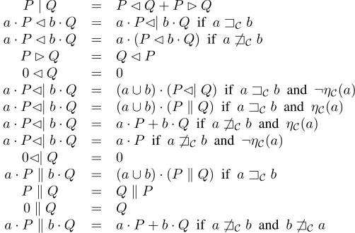
Figure 4. Phase Transition Process Algebra
We define processP to be the phase transition represen-tation of processesQiwhenP DC Qifor eachi. Define the
overlaps ofP to be those phase transition traces ofP that are not contained in any of theQi.
7. Phase Transition Processes
In figure 4 we briefly describe a process algebra that defines how to synthesise a phase transition representation from a set of processes described by the requirements sce-narios. The algebra essentially defines an algorithm for the construction of a minimal phase transition representation as explained in theorem 7.1.
LetAbe the set of annotated events. Let+be the usual choice operator over process terms. Let·be the usual com-position operator of atomic actions and process terms. Let ηC : A −→ B be a boolean valued function that de-fines when an annotated event is a phase transition. That is ηC(S, e, S0) = t when 6` C ⇒ (
V
S ⇒ VS0). For an-notated eventsa = (S, e, S0) and b = (U, e, U0) define a∪b= (S∪U, e, S0∪U0).
Proposition 7.1 Given a setQ of processes Qi from
re-quirements scenariosMifor0≤i≤n, then
P =Q0|Q1| · · · |Qn
is a phase transition representation ofQ. Where|is defined by the axioms of figure 4.
If P0 is another phase transition representation of Q, thenP0 AC P. That is P is canonical up to simulation equivalence. DefinePto be the phase transition process for Q.
Figure 3 describes one of the overlaps given by the phase transition process of the ‘Browser’ processes in figure 1 and figure 2.
Given that we have a context whereActive and’Load File’are valid at the same time, figure 3 can be viewed as an abstract form of ‘cut’ and ‘paste’ of the two scenarios in figure 1 and figure 2.
In order to simply depict a phase transition process we define a straightforward translation into a state machine de-scription.
Definition 7.2 A phase automaton consists of a set of events E, states P and transitions from P × E × P. A phase automaton also has a functionψ:P −→2Ph.
Given a process that has annotated events for actions, we can simply translate it into a phase automaton consisting of the following state transitions. Each action transitionP −→a
P0, wherea= (S, e, S0), defines a state transitionu−→e u0 for eachu∈ψ−1(S), andu0 ∈ψ−1(S0).
It turns out that the phase automaton defined by the phase transition process of a collection of processes from MSC scenarios is always regular:
Proposition 7.3 The phase automaton of a phase transition process is always finite.
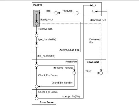
Figure 5 is the phase transition process of the two ‘Browser’ processes defined in figures 1 and 2. Those states that be-long to the same phase are grouped together in a box la-belled with the phase name, resulting in a state chart like diagram. The dotted arrows represent the part of the pro-cess behavior that is exclusive to figure 1. The solid arrows are the behavior that is defined by figure 2.
?send(file_handle) !ack
?load(URL)
?activate
Download File
!download_OK
Resolve URL
!get_handle(file)
?file_handle(file)
!read(file_handle)
Check For Errors
Check For Errors
corrupt_file(file)
?EOF
Inactive
Active, Load File
Read File
Error Found
[image:7.595.63.544.73.442.2]Download
Figure 5. ‘Browser’ Phase Transition Process
The phase transition process P is built by joining to-gether specification scenario processes wherever there is a match between phase transition traces. The process algebra of figure 4 captures this idea formally.
For an annotated eventa = (S, e, S0)let∗a = e. Let P be a process that has annotated events as actions. LetA be a state machine that accepts some subset ofE∗. Define AA P, if for allP −→a P0 there is someA −→∗a A0 such thatA0 AP0. That is when reduced to a process over plain eventsPcan be simulated byAin the usual sense.
Proposition 7.4 LetP be the phase transition representa-tion of a set of processesQifrom MSC scenariosMi, where
the temporal contextCis a tautology.
LetAbe the state chart of theQi processes defined
ac-cording to the semantics of [10] where each set of phase names attached to a phase symbol from theMiis mapped
to a unique state name. ThenAAP.
This shows that the phase transition semantics here weak-ens the state based semantics of [10] so that less
composi-tions are legitimate, which is intended to reflect the impre-cise nature of industrial scenarios.
7.1. Conclusions
Around a third of significant defects can be traced to re-quirements specifications. Hence it is important to be able to construct a model of possible compositions of the require-ments as an analytic tool to facilitate the detection of such defects. Such a model is also useful in ensuring sufficient coverage of test cases for feature interactions implied by the requirements, which are often caused by composition between requirements for different features.
between scenarios. This ensures composition occurs only where phase symbols have consistent state like definitions.
The research reported in this paper is a consequence of case studies of Motorola requirements scenarios. The work reported here has been incorporated into the ptk tool suite [6], has been validated against a suite of industrial require-ments specifications, and is being applied in a pilot study for a new mobile handset for Motorola.
References
[1] R. Alur and M. Yannakakis, Model checking of message sequence charts, Proceedings of the Tenth International Conference on Concurrency Theory, Springer Verlag, 1999 [2] R. Alur, K. Etessami, M. Yannakakis, Inference of Message
Sequence Charts, Proceedings 22nd International Conference on Software Engineering, pp 304-313, 2000. [3] Yves Bontemps, Patrick Heymens, Turning high-level live
sequence charts into automata, Proc of Scenarios and State Machines: Models Algorithms and tools, 24th International Conf. on Software Engineering, May 2002, ACM. [4] European Telecommunications Standards Institute,
http://www.etsi.org
[5] T. Gehrke, M. Hilhn, H. Wehrkeim, An Algebraic Semantics for Message Sequence Chart Documents, in Formal Description Techniques, Chapman Hall 1998. [6] P. Baker, P. Bristow, C. Jervis, D. King, B. Mitchell,
Automatic Generation of Conformance Tests From Message Sequence Charts, Proceedings of 3rd SAM Workshop 2002, Telecommunications and Beyond: The Broader
Applicability of MSC and SDL, pp 170-198, LNCS 2599. [7] Yves Bontemps, Pierre-Yves Schobbens, Synthesis of Open
Reactive Systems from Scenario-Based Specifications, Third International Conference on Application of Concurrency to System Design (ACSD’03) [8] M. Hennessy, R. Milner, Algebraic Laws for
Nondeterminism and Concurrency, Journal of the ACM, 32: 137-161, 1985.
[9] Werner Dam, David Harel, LSCs: Breathing life into message sequence charts, Formal Methods in System Design, 19(1):45-80, 2001.
[10] Sebastian Uchitel, Jeff Kramer, Jeff Magee, Synthesis of Behavioral Models from Scenarios, IEEE Transactions on Software Engineering, vol. 29, no. 2, February 2003 [11] Annex C, Service Diagrams related to the model of Mobile
user, Terrestrial Trunked Radio (TETRA); Voice plus Data (V+D); Designers’ guide; Part 2: Radio channels, network protocols and service performance, European
Telecommunications Standards Institute 1997.
[12] E. Wong, J. R. Horgan, W. Zage, D. Zage and M. Syring, Applying Design Metrics to a Large-Scale Software System, (Motorola), Proceedings of the 9th International Symposium on Software Engineering Reliability (ISSRE 98), Paderborn, Germany, November 4-7, 1998.