Abstract — This paper deals with the design, implementation and experimental validation of a complete, electrical drive system, for linear actuation in an aerospace environment, with the main requirements being high force/power density, reliability, availability and fault tolerance. A directly-driven, linear, high force density, tubular motor supplied from a matrix converter for a rotorcraft application is specifically considered. Design aspects of both motor and converter are presented, while an overview of the implementation aspects for the complete drive system is also given. Precise control structures are proposed and tested. Experimental results are presented and compared to the calculated design values. This work shows how the combination of high performance components can achieve a high performance drive in terms of power density and force density.
Index Terms — aerospace, high power/force density, matrix converter, more electric aircraft, tubular motor
I. INTRODUCTION
HE more electric aircraft (MEA) initiative [1, 2] seeks to reduce or remove the reliance on traditional, hydraulic, pneumatic and mechanical systems from aircraft. The concept has been around for the past few decades [1], however improvements in the electrical systems in terms of weight and reliability are still highly required [3, 4].
Nowadays, linear force actuation such as required for the control of the primary and secondary flight control surfaces (FCS) is achieved by the use of electro-mechanical actuators (EMA) and/or electro-hydraulic actuators (EHA). Their wide-spread use is still however limited mainly due to their reliability. A major bottleneck is the probability of jamming, synonymous with the mechanical drive-train of such actuation systems. Adopting direct drive (DD), linear electro-magnetic machines (linear motors) can result in considerable simplifications in terms of the above issues, mainly through the absence of any mechanical gearing and/or ball/roller screws. The main challenge with linear motors is however their inherent inability to achieve the required performance in terms of force-to-mass and force-to-volume ratios as is expected from their mechanically geared, rotational counterparts [5]. A high force density, state of the art, tubular linear permanent magnet (TLPM) motor has been designed and experimentally validated in previous publications [6, 7].
In order to drive such a motor, a typical drive system usually makes use of a standard power converter. However, considering the push towards optimizing weight, reliability and fault
Michael Galea and Giampaolo Buticchi are with the Power Electronics, Machines and Control Research Group of the University of Nottingham Ningbo China. Michael Galea is also with the University of Nottingham, UK.
tolerance of the whole drive system being addressed in this paper (aerospace applications), then it is important to note the typical issues synonymous with standard power converters. In fact, apart from the well-known, low power density values (high relative weight and volume) of such converters, another main issue to consider for the power converter is the damage caused by power cycling and uneven loss distribution among the power devices when the output frequency is similar to that of the input frequency [8]. The output inverter stage of a typical voltage source inverter (VSI) drive will suffer from power cycling issues where the output frequency is close to zero since there will be a slowly changing and unequal loss distribution in the switching devices. The upper devices will suffer an increased loss during the positive output half cycle and similarly the lower device will exhibit an increased loss in the negative half cycle. For the application considered in this work, which involves a constant, position locking operation at stand-still, significant zero speed operation at high load currents is typical and as such a VSI based drive would have to be overrated in order to guarantee longevity. On the other hand, a matrix converter (MC) is a direct AC-AC power converter topology. In the configuration required for this application a three input, three output MC will consist of a ‘matrix’ of nine bi-directional switches where any input supply phase can be connected to any output load phase at any point in time. With the appropriate control and modulation, the gating of the devices can be modulated to achieve the desired output voltage. The input frequency to the power converter in this case is the 50 or 60Hz
supply and as such, zero speed load holding is the best condition for thermal cycling [9]. This topology was therefore chosen in order to test and validate the above-mentioned TLPM motor.
Thus, the objective of this paper is mainly to investigate the design aspects and the incorporation of the above high end components into one complete drive that results in a high performance system with excellent performances in terms of power and force density.
II. DESIGN,CONSTRUCTION AND IMPLEMENTATION
In this section, brief reviews of the design, construction and implementation of the TLPM motor and the MC as stand-alone devices are given. The design procedures including the analytical modelling of the TLPM motor are presented, while the concept and the design aspects of the MC are also given.
Development of a high force density,
actuation drive for an aerospace application
Michael Galea, Giampaolo Buticchi
A. The TLPM motor
The design and optimization procedures of the TLPM motor are mainly given in [6]. The single air-gap, double layer, 12-slot/10-pole, fluid-cooled, TLPM motor, whose main structure is shown in Fig. 1, is fitted with inset permanent magnets (IPM) and the main design constraint for the machine is the available external envelope.
Fig. 1 Structure of the TLPM motor with IPMs
Assuming no iron losses in both stator and mover and neglecting harmonic effects due to the electrical loading, then the no load, air-gap flux density Bg can be described by (1), where Brem is the PM residual flux density and μrrec is the PM relative recoil permeability.
2
1
1 2
1
The electrical loading Arms is dependent on the thermal management and material properties of the machine [10]. As shown in [6], the TLPM motor is fitted with a novel, thermal management technique [11], that reduces the thermal resistance from the centre of the stator coils to the cooling arrangement, by the adoption of a high thermal conductivity heat-path (HP). A fluid cooled arrangement is adopted and the thermal/electrical limits can be computed using a lumped parameter, thermal network as shown in Fig. 2, where R1 – R12 and RHP1 – RHP3 are the thermal resistances and whose derivations are given in [11].
Having a maximum permissible winding temperature Tmax, the maximum value of copper losses Pcu for each coil can be found. The maximum value of the copper current density Jrms (and thus Arms) can be found from (2), where ρcu is the resistivity of copper at a given winding temperature and Kfill is the slot fill factor.
2
The peak thrust force generated by the machine can then be computed from (3) where Bg1 is the fundamental component of the air-gap flux density distribution, P is the number of pole pairs and (4πRinPTp) is the total active surface area of the mover. √2 4 3
Fig. 2 Lumped parameter thermal network with HP
4
sin
2 4
Using the above, the optimum split ratio and tooth width to slot width ratio for maximum force can be found. The design is initiated by considering any fixed parameters such as the external length Le, external radius Re and Brem and μrrec. Then using (1) – (4), the optimum geometrical dimensions can be found. The analytical models above are used to provide adequate starting points for a more accurate finite element (FE) model, such as shown in Fig. 3.
Fig. 3 Final FE model with HPs
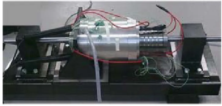
A prototype machine of the TLPM motor with fluid cooling and HPs in the slot was manufactured and assembled. Fig. 4 shows a photo of the motor.
Fig. 4 The TLPM motor prototype
B. The matrix converter
made to be sinusoidal and depending on the load conditions, unity displacement factor at the input is also possible. As a direct AC/AC solution, a MC does not require electrolytic DC-link capacitors or large input inductors. A small input filter is necessary to reduce the line side switching harmonics of the system. The lack of bulky, passive components allows the MC technology to offer power and volume density features which are desirable in motor drives for aircraft applications.
Fig. 5 The 9 switch, 3 phase to 3 phase MC
One potential drawback to this converter is that, in order to ensure a sinusoidal input current, the output voltage transfer ratio is limited to 0.86. This however is not a drawback, if the required voltage of the load is less than this value, as is the case in this application. In order to implement a MC, a suitable bi-directional switch however must be implemented which can carry both the current in either direction and block the voltage in both directions. Potential arrangements are described and investigated thoroughly in [12].
For this application, a high current, 100kW, MC is used to drive the actuator. It has been designed and constructed using modified E-type industrial power modules. Each module contains three common emitter connected bidirectional switches and hence three of these modules are used to construct the converter. The module uses 1700V, 600A IGBTs and 500A, 1200V, silicon carbide (SiC) diodes (using 50A chips) to reduce the losses associated with the commutation process. The modules are directly mounted onto individual water jacket heat exchangers. Power planes are used to connect the input filter capacitors and the power circuit. A high speed diode bridge clamp with active energy dump, similar to that described in [13] is included to provide fault protection. The converter is controlled using a high speed floating point DSP (C6713) and an FPGA to provide all of the necessary PWM generation and A2D interfaces. The controller implements a space vector PWM generator and has a minimum output vector time of 20ns
with an edge resolution of 20ns. High speed, low jitter, fibre optic channels are used to transfer the PWM demand signals to the gate drive circuits.
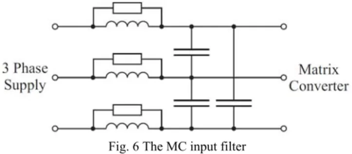
Considering that the input supply frequency for this application varies in the range of 360-800Hz and that the switching frequency is 12.5kHz then in order to avoid interference between these frequencies and their harmonics, a resonant frequency between 4 to 5kHz has been initially assumed. A parallel damped single section filter configuration was chosen for this application as shown in Fig. 6, where a resistor is placed in parallel with the inductor to provide appropriate damping according to the value of resistance R
selected. A very small value of R would result in a high degree of damping but a higher dissipation of energy.
Simulations of the input filter connected between the input supply and the converter have been run to fine tune the values of both the capacitance, the inductance and the resistor. Due to the necessary AC current rating of the capacitor, several capacitors were used in parallel in order to create 10μF line to line. Three single phase inductors of 50H, rated at 800Hz and three 8 resistors have also been implemented.
Fig. 6 The MC input filter
One key difference between a VSI and a MC is that there are no freewheeling paths in a MC and as such the commutation of the load current between the input phases without generating input short circuits or output open circuits, needs to be carefully managed. There are many ways of achieving a safe current commutation [14, 15] and these can generally be separated into two groups depending on the type of information that is used to derive the switch sequence used.
The process of commutating the current is generally a multi-step process. The choice of the commutation technique depends on the requirements of the application but one critical aspect to be considered is the effect on the converter of a commutation process failure. If an overvoltage clamp protection circuit is used then it is preferable to cause an open circuit of the load since there is very little that can be done to protect a power converter from a short circuit of its voltage source and as such, four-step current direction based commutation is used for the power converter.
The derivation of the current direction information needs to be as accurate and noise free as possible. The method uses the inherent voltage drop across the power devices to provide high quality information. The gate drive card for each output phase contains an FPGA which uses the voltage polarity information in order to calculate the current direction in its output phase and perform the current commutations demanded by the controller. The voltage polarity is obtained by measuring the voltage drop across the anti-parallel diode of the IGBT, whose circuit is shown in Fig. 7. A CMOS protection circuit with a resistor Rov and a diode Dov protect the comparator when the diode is blocking the full reverse voltage.
L
I
D
V
D
V VD/
V
5
ov
R ov
D
C. The complete drive
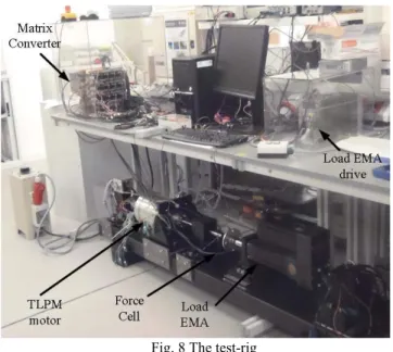
The MC and the TLPM motor are assembled on a test-rig that comprises an industrial, 40kW, load EMA capable of peak force loads of up to 17.8kN, with a maximum stroke of 300mm at a maximum linear velocity of 313mm/s. Fig. 8 shows a photo of the test rig.
Fig. 8 The test-rig
III. CONTROL AND EXPERIMENTAL VALIDATION
In this section, the general control scheme of the system is proposed and presented. The scheme is then used to acquire effective and accurate measurements of the required TLPM motor performances.
The control of the TLPM motor is realized by nested feedback, where the innermost loop is represented by the field-oriented force control. A linear transducer is employed for the speed and linear position feedback. While optic scales could be employed for this purpose, in this test-rig, a rack-gear coupling was used to convert the linear movement to a rotational one, allowing the use of a standard resolver.
The control of PM synchronous machines (PMSM) has been widely studied in literature, and several methods for the controllers’ direct tuning are available in literature [16]. Nested loops are employed in order to accurately limit the maximum acceleration and current. In particular, when the motor is in standstill operations, the FOC is still online. This represents a more advanced control with respect to the positioning system based on stepper motors where the standstill operation is realized by exciting a single phase.
The block scheme of the control of the TLPM motor is shown in Fig. 9. The resolver angle θm is processed in order to calculate the linear position θlin and velocity Vlin and the electric angle θe employed in the FOC. Simple Proportional-Integral (PI) regulators are employed for the current and speed control, while a Proportional-Derivative (PD) regulator realizes the position loop. At the output of the current regulators the decoupling terms are added. The electrical speed ωe is calculated from θm.
Fig. 9 Control scheme of the complete system
A. No load electro-motive force
With the MC disconnected, the load EMA is controlled with a square-wave speed demand so as to act as a prime mover that smoothly translates the mover of the TLPM motor at a constant
Vlin of 100mm/s. Using a high bandwidth oscilloscope, the terminal voltages of the motor are acquired. Fig. 10 shows the excellent agreement between the FE results and the experimentally measured waveforms. The FE waveform shows a slightly higher fundamental, which error can be attributed to experimental tolerances.
Fig. 10 No load back-EMF
B. Force capability
Fig. 11 Current demand of the TLPM motor
For these tests, suitable parameters of the regulators are chosen in order to have a slow increase of the applied force to prevent damage to the force cell. The test is repeated for different positions of the TLPM and averaged in order to be able to neglect the cogging force Fcog from the measured result. Fig. 12 shows the measured results for increasing values of Ipk and also compares them to the FE-predicted results. As can be observed in Fig. 12, a very good similarity exists between the predicted and the measured results, thus validating the TLPM motor design procedures and also the control scheme accuracy. Any remaining FE-prediction errors can be attributed to inaccuracies in measurement due to the load cell tolerance (±1% of full scale measurement), human error and manufacturing and material properties tolerances.
Fig. 12 TLPM motor force capability
C. Force constant
The results shown in Fig. 12 can be used to plot the predicted and measured values of the force constant KF of the TLPM motor. Fig. 13 illustrates and compares the FE and experimental results, where it can be observed that for the motor rated value of Ipk = 54.05A, the error between the FE and experimental results is approximately 2.48%.
Fig. 13 Force constant KF
D. Cogging force
Having achieved an accurate characterization of the current-force capability, it is also possible to indirectly measure the cogging force Fcog of the TLPM motor. To achieve this, the load EMA is mechanically disconnected from the TLPM motor and then position control is used to realize a very slow-moving linear translation of the mover. Neglecting any values of kinetic friction, then this translation motion can be described by (5), where KF [I(t)] represents the KF characteristic shown in Fig. 13 and m is the mass of the mover.
. 5
As θlin and I(t) are sampled at a high sampling frequency (12.5kHz) and m is known from experimental measurement, then the experimental Fcog can be calculated via the numerical method, described by (5). In fact, even if the test is realized with very slow linear speeds, Fcog calculated in this way is affected by a finite DC component, that corresponds to the linear friction. A high-pass filter can be used to eliminate this DC component from the calculation of Fcog.
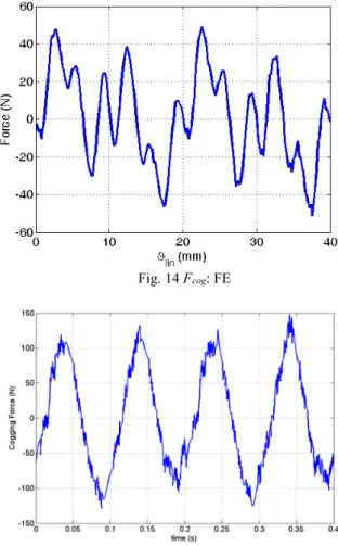
Fig. 14 illustrates the FE-predicted Fcog. Fig. 15 shows the experimental measures obtained using (5). The difference in the shape of the waveforms can be safely attributed to load cell and material tolerances, while the main cause for the discrepancy is probably the physical presence of ferro-magnetic components (such as the mounting angle-plates, which can be observed in Fig. 4) which are not modelled in the FE model of Fig. 3.
Fig. 14 Fcog: FE
IV. CONCLUSION
The experimentally measured, performance capability of the TLPM motor is presented and compared to its predicted capability in Fig. 10 - Fig. 15. The results shown, confirm the reliability of the models used for the design and analysis of the TLPM motor. However they also indicate the high force capability of the manufactured TLPM motor. In fact, with measured force density values of 381.42kN/m3 and 91.51N/kg, the TLPM motor compares excellently with other manufactured prototypes of high force density, linear motors, such as those, whose results are published in available literature [17, 18]. In this paper, the TLPM motor was “coupled” to a high performance, MC with a measured power density of 3.85kW/kg. Another advantage of choosing and implementing the MC topology for the application at hand, where operation is mostly at zero speed resides in the fact that as mentioned and explained in Section I, the thermal stress on the active devices is lower than that of a traditional VSI. This was a major factor in the choice of the converter topology.
In this work, it has been shown how two, high end, state of the art systems such as the TLPM motor and the MC can be successfully implemented into a complete drive system. As illustrated above, the end result is a drive that is capable of satisfying the required application specifications in terms of force and force density while conforming to the highly demanding requirements of reliability, fault tolerance and availability that are so exigent in the aerospace industry.
ACKNOWLEDGMENTS
This work was partially supported by the Ningbo Science & Technology Bureaux under Grant 2014A35007.
REFERENCES
[1] R. I. Jones, "The More Electric Aircraft: the past and the future?," in Electrical Machines and Systems for the More Electric Aircraft (Ref. No. 1999/180), IEE Colloquium on, 1999, pp. 1/1-1/4. [2] A. Boglietti, A. Cavagnino, A. Tenconi, and S. Vaschetto, "The
safety critical electric machines and drives in the more electric aircraft: A survey," in Industrial Electronics, 2009. IECON '09. 35th Annual Conference of IEEE, 2009, pp. 2587-2594.
[3] C. Gerada, M. Galea, and A. Kladas, "Electrical machines for aerospace applications," in Electrical Machines Design, Control and Diagnosis (WEMDCD), 2015 IEEE Workshop on, pp. 79-84.
[4] M. Galea, T. Hamiti, and C. Gerada, "Torque density improvements for high performance machines," in Electric Machines & Drives Conference (IEMDC), 2013 IEEE International, pp. 1066-1073. [5] G. W. McLean, "Review of recent progress in linear motors,"
Electric Power Applications, IEE Proceedings B, vol. 135, pp. 380-416, 1988.
[6] M. Galea, G. Buticchi, L. Empringham, L. De Lillo, and C. Gerada, "Design of a High-Force-Density Tubular Motor," Industry Applications, IEEE Transactions on, vol. 50, pp. 2523-2532, 2014. [7] M. Galea, C. Gerada, T. Raminosoa, and P. Wheeler, "Design of a
high force density tubular permanent magnet motor," in Electrical Machines (ICEM), 2010 XIX International Conference on, 2010, pp. 1-6.
[8] X. Perpina, X. Jorda, M. Vellvehi, J. Rebollo, and M. Mermet-Guyennet, "Long-Term Reliability of Railway Power Inverters Cooled by Heat-Pipe-Based Systems," Industrial Electronics, IEEE Transactions on, vol. 58, pp. 2662-2672, 2011.
[9] L. De Lillo, L. Empringham, P. Wheeler, J. Clare, and K. Bradley, "A 20 KW matrix converter drive system for an electro-mechanical aircraft (EMA) actuator," in Power Electronics and Applications, 2005 European Conference on, 2005, pp. 6 pp.-P.6.
[10] C. Sciascera, P. Giangrande, L. Papini, C. Gerada, and M. Galea, "Analytical Thermal Model for Fast Stator Winding Temperature Prediction," IEEE Transactions on Industrial Electronics, vol. 64, pp. 6116-6126, 2017.
[11] M. Galea, C. Gerada, T. Raminosoa, and P. Wheeler, "A Thermal Improvement Technique for the Phase Windings of Electrical Machines," Industry Applications, IEEE Transactions on, vol. 48, pp. 79-87, 2012.
[12] M. Bland, P. Wheeler, J. Clare, and L. Empringham, "Comparison of calculated and measured losses in direct AC-AC converters," in Power Electronics Specialists Conference, 2001. PESC. 2001 IEEE 32nd Annual, 2001, pp. 1096-1101 vol.2.
[13] L. Empringham, L. De Lillo, P. W. Wheeler, and J. C. Clare, "Matrix Converter Protection for More Electric Aircraft Applications," in IEEE Industrial Electronics, IECON 2006 - 32nd Annual Conference on, 2006, pp. 2564-2568.
[14] N. Burany, "Safe control of four-quadrant switches," in Industry Applications Society Annual Meeting, 1989., Conference Record of the 1989 IEEE, 1989, pp. 1190-1194 vol.1.
[15] L. Empringham, P. Wheeler, and J. Clare, "Power density improvement and robust commutation for a 100 kW Si-SiC matrix converter," in Power Electronics and Applications, 2009. EPE '09. 13th European Conference on, 2009, pp. 1-8.
[16] A. Lidozzi, V. Serrao, L. Solero, F. Crescimbini, and A. Di Napoli, "Direct Tuning Strategy for PMSM Drives," in Industry Applications Society Annual Meeting, 2008. IAS '08. IEEE, 2008, pp. 1-7.
[17] N. Bianchi, S. Bolognani, D. D. Corte, and F. Tonel, "Tubular linear permanent magnet motors: an overall comparison," Industry Applications, IEEE Transactions on, vol. 39, pp. 466-475, 2003. [18] W. Jiabin, W. Weiya, and K. Atallah, "A Linear Permanent-Magnet