A Branch Current Reallocation Based Energy Balancing
Strategy for the Modular Multilevel Matrix Converter
Operating Around Equal Frequency
Boran Fan
1, Kui Wang
1, Chunyang Gu
2, Pat Wheeler
2, Yongdong Li
11
State Key Lab of Power System, Dept. of Electrical Engineering, Tsinghua University, Beijing, China
2Department of Electrical and Electronic Engineering, University of Nottingham, Nottingham, United Kingdom
E-mail: [email protected]
Abstract—Modular multilevel matrix converter (M3C) is a
promising topology for medium-voltage high-power applications. Due to the modular structure, it features easy scalability, high quality output waveforms and superior fault tolerance. However, M3C suffers serious capacitor-voltage fluctuation if the output frequency gets closer to the input frequency. This limits its use in the adjustable-speed-drive (ASD) applications. This paper introduces a theoretical analysis in phasor-domain to find the branch energy equilibrium point of M3C when operating around equal frequency. On the basis of this equilibrium point, a branch current reallocation based energy balancing control method is proposed to equalize the energy stored in the nine converter branches. With this novel control method, M3C can effectively
overcome the capacitor voltage fluctuation with neither using common voltage nor applying reactive power at the input side.
Keywords—modular multilevel matrix converter (M3C); energy and balancing control; equal frequency
I. INTRODUCTION
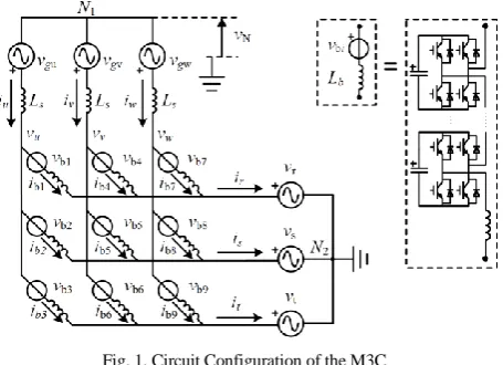
The modular multilevel matrix converter (M3C), shown in Fig. 1, connects two three-phase systems (input-side and output-side) by nine branches. Each branch is a cascaded connection of full-bridge (H-bridge) converter cells. It enables direct AC-AC bidirectional power conversion and ensures three-phase input and output currents sinusoidal with any power factor [1]-[4]. Like other members of the modular multilevel cascade converter (MMCC) family, the voltage ratings of M3C can be enhanced easily by increasing the number of cascaded cells. M3C is more suitable for low-speed constant-torque motor drives compared with the modular multilevel converters (MMC) in back-to-back configuration [5], [6]. These advantages make M3C a promising topology for the medium-voltage high-power adjustable-speed-drive (ASD) application. However, M3C suffers serious capacitor-voltage fluctuation if the output frequency gets closer to the input frequency. This is caused by a very low-frequency (the frequencies’ difference between two three-phase system) reactive power on the branch. This reactive power becomes constant when both systems are with identical frequency. It causes power difference among branches and as a result, unbalances the energy stored in different branches.
In order to solve this problem, [2] presents a solution by both injecting circulating current into M3C and applying reactive power at the input side. However, a reactive power at the input side is not allowed in some cases as input side is mostly connected to the grid. Reference [4] introduces common voltage to avoid reactive power at the input side
[image:1.595.317.545.348.513.2]which is similar to the mitigation control of the MMC at low-speed range [7]. However, the reference common voltage is difficult to design and may cause over-modulation. The common voltage may also lead to premature failure of motor bearings. Reference [8] adjusts the motor voltage to ensure the input and output side share a same voltage magnitude. This helps to achieve lower branch currents. But this method has a few restrictions and also needs to apply reactive power at the input side.
Fig. 1. Circuit Configuration of the M3C
As the reactive power at the input side is not allowed in some conditions and the common voltage may cause serious problems, this paper attempts to develop a control method only using circulating currents in the M3C to equalize the energy of the nine branches. This paper firstly proves the availability of this consideration. Then it develops a strategy to design specifically appropriate circulating currents. With this control method, M3C can effectively overcome the capacitor voltage fluctuation with neither using common voltage nor applying reactive power at the input side. The proposed control strategy has been validated by simulation and experiment.
II. BASIC THEORY OF THE M3C
A. Double αβ0 Transformation
In the M3C, there are four independent inner circulating currents [1]-[4]. These circulating currents are independent of input side currents (iu, iv, iw) and output side currents (ir, is,
it). Power transfer between different branches is realized by
currents are defined as iαα, iαβ, iβα and iββ. The definition of
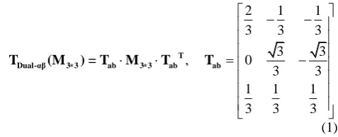
the double αβ0 transformation TDual-αβ is in (1).
2 1 1
3 3 3
3 3
, 0
3 3
1 1 1
3 3 3
T
Dual-αβ 3 3 ab 3 3 ab ab
T (M ) = T M T T
(1)
Perform the double αβ0 transformation on nine branch currents and gets the iαα, iαβ, iβα andiββ in (2). Here iα0 and iβ0
are components of the input currents on the α-axis and β-axis and iα0 and iβ0 are components of the output currents on the
α-axis and β-axis.
0 1 2 3
0 4 5 6
0 0 00 7 8 9
=
b b b
b b b
b b b
i i i i i i
i i i i i i
i i i i i i
T ab ab
T T (2)
The double αβ0 transformation also helps to realize a decoupled control of these four circulating currents as shown in Fig. 2 [9]. Using simple proportional-integral (PI) regulators, the iαα, iαβ, iβα andiββ are easily controlled by vαα,
vαβ, vβα andvββ. Here,voltagevαα, vαβ, vβα andvββ are defined in
[image:2.595.50.289.80.177.2](3).
Fig. 2. Circulating currents and common-voltage in the M3C
0 1 2 3
0 4 5 6
0 0 00 7 8 9
b b b
b b b
b b b
v v v v v v
v v v v v v
v v v v v v
T ab ab
T T (3)
The value of the common voltage vN in Fig. 1 is equal to
the value of v00 as shown in Fig. 2. In order to avoid
common-voltage, according to (1) and (3), the value of v00
satisfies (4). 9 00 1 1 0 9 N bi i
v v v
@ (4)B. Basic Branch Current Allocation
If control circulating currents iαα, iαβ, iβα andiββ all to be
zero, the nine branch currents would be (5). The branch current consists of 1/3 of the x-phase (x=u,v,w) input side current and 1/3 of the y-phase (y=r,s,t) output side current.
0,1 0,2 0,3 0,4 0,5 0,6 0,7 0,8 0,9
1 1
3 3
b b b u u u r s t
b b b v v v r s t
b b b w w w r s t
i i i i i i i i i
i i i i i i i i i
i i i i i i i i i
(5)
In this paper, the branch currents in (5) are defined as the “basic branch current”. Recent literatures mostly assume this branch current allocation as the branch energy
equilibrium point. On the basis of this allocation, circulating currents iαα, iαβ, iβα and iββ are designed to
compensate possible branch energy difference.
C. Capacitor-voltage Fluctuation
In this paper, the input and output systems are assumed to be three-phase balanced and with positive sequence. No reactive power is applied at the input side. Voltages and currents at the input and output side are defined as,
1 1
ˆ cos( )
u m
v v t (6)
1 1
ˆ cos( )
u m
i i t (7)
2 2
ˆ cos( )
r m
v v t (8)
2 2
ˆ cos( )
r m
i i t (9)
Applying the basic branch currents allocation defined in (5), the power on branch 1, for instance, is shown in (10). This branch power consists of frequency components of ω1
-ω2, ω1+ω2, 2ω1, 2ω2.
1
1 2 1 2 2 1 2 2
( ) ( ) / 3
| | | |
b u r u r
h
p v v i i
p p p p
p
1 4 4 4 44 2 4 4 4 4 43 (10)
When output side frequency (ω2) gets close to the input
side frequency (ω1), the low-frequency power component of
ω1-ω2 causes large branch energy fluctuation. This power
component is shown in (11) and (12). In conclusion, when operating M3C around equal frequency, applying the basic branch currents allocation causes large branch energy fluctuation. Therefore a branch currents reallocation should be developed.
1 2
2 2 2 2
1 2 2 1 1 2 1 2
1 2
| =
ˆ ˆ ˆ ˆ
ˆ ˆ 2ˆ ˆ cos
cos[( ) ]
6
m m m m m m m m
p
v i v i v v i i
t (11) 1 2
1 2 2 1
ˆ
ˆ sin
arctan( ˆ ˆ )
ˆ cos ˆ
m m
m m m m
v i
v i v i
(12)
III. BRANCH ENERGY EQUILIBRIUM POINT OF M3C WHEN OPERATING AROUND EQUAL FREQUENCY
A. Phasor-domain Analysis of the M3C
In this paper, analysis is performed in phasor-domain instead of time-domain. This helps to visualize the analysis of branch energy balancing for the equal-frequency operation. Assuming ω1=ω2, rewritten the definition of
(6)-(9) in phasor-domain,
0 1
ˆ j
u m
vr v e (13)
0 1
ˆ j
u m
i i e
r
(14)
2
ˆ j
r m
vr v e (15)
( ) 2
ˆ j
r m
i i e
r
(16)
0,1 0,2 0,3 0,5 0,6 0,4 0,9 0,7 0,8
1 1
3 3
b b b u u u r s t
b b b v v v r s t
b b b w w w r s t
i i i i i i i i i
i i i i i i i i i
i i i i i i i i i
r r r r r r r r r
r r r r r r r r r
r r r r r r r r r (17)
In (18), eni(i1, 2,..9)
r
is the unit length phasor that leads branch voltage v ibi( 1, 2,..9)
r
by 90º as in (19).
1 2 3 4 5 6 7 8 9
T
n n n n n n n n n
e e e e e e e e e
n
[e ] = r r r r r r r r r (18)
cos sin , ( 1, 2,..9)
| |
bi j bi
ni bi bi
bi
v
e j e j i
v r r @
r (19)
Here [e ]n is separated into three groups as [en1,5,9],
2,6,7
n
[e ] and [en3,4,8]. In each group, ern1/ern2 /ern3 leads
5 n
er /ern6/ern4 120º and ern5/ern6/ern4 leads ern9/ern7/ern8 120º respectively as in (20)-(22).
21,5,9 1 5 9 = 1 1
j j
n n n n
e e e e e e
n
[e ] r r r r (20)
22,6,7 2 6 7 = 2 1
j j
n n n n
e e e e e e
n
[e ] r r r r (21)
23,4,8 3 4 8 = 3 1
j j
n n n n
e e e e e e
n
[e ] r r r r (22)
Fig. 3 is the phasor diagram of the M3C, input side voltage and currents in (13) and (14) are shown in red color; output side voltage and currents in (15) and (16) are shown in green color; basic branch currents in (17) are shown in purple color; [e ]n are shown in blue color. Obviously, in order to stabilize branch energies, there should be no active power on each branch. Therefore the branch current phasor
( 1, 2,..9) bi
i i
r
should be in the same or opposite direction with e ini( 1, 2,..9)
r
. This condition is explain in (23)-(25). Here
C is the vector of nine branch currents magnitude. [image:3.595.364.494.48.213.2](a) (b) u v w v v v r v t v s v s i r i t i w i u i 3 n e 8 n e 4 n e 0,4 b i 0,8 b i 0,3 b i v i (c)
Fig. 3. Phasor Diagram of the M3C (a) Branch 1,5,9 (b) Branch 2,6,7 (c) Branch 3,4,8
However, in Fig. 3 the basic branch current phasors are clearly with phase difference to [e ]n and do not meet the condition in (23). This causes a branch energy derivation when ω1=ω2 and a large branch energy fluctuation when
ω1≈ω2. This result is consist with the analysis in
time-domain as explain in PART II.C.
ib C [e ] n (23)
1 2 3 4 5 6 7 8 9T
b b b b b b b b b
i i i i i i i i i
b
i r r r r r r r r r (24)
C c1 c2 c3 c4 c5 c6 c7 c8 c9
(25)B. Branch Current Magnitude Calculation
As input and output side are three-phase balanced, the value of branch current magnitudes c1, c5 and c9 are equal
and so as c2, c6, c7 and c3, c4, c8 as shown in (26).
1 5 9, 2 6 7, 3 4 8
c c c c c c c c c (26)
Branch currents satisfy,
1 2 3 1 1 2 2 3 3
u b b b n n n
ir ir ir ir c er c er c er (27)
2
1 4 7 1 1 2 2 3 3
j j
r b b b n n n
ir ri ir ri c er c e er c eer (28)
Combined with (14) and (16), the branch currents magnitudes satisfy,
[A][C] = [B] (29)
Where,
1 2 3
1 2 3
1 2 3
sin sin sin
sin sin( 2 ) sin( )
cos cos( 2 ) cos( )
b b b
b b n b n
b b n b n
[A] (30)
2 2
ˆ ˆ
0 im sin( ) im cos( )
[B] (31)
[image:3.595.311.549.311.378.2]C. Disscussion on the Control Availability
This paper attempts to develop a control method only using circulating currents in the M3C to equalize the energy of the nine branches. The availability of this consideration is equivalent to the solvability of the linear equation in (29).
Assume modulation rate m as,
2 1
ˆm /ˆm 0
mv v (32)
It is proved that the mentioned consideration is possible under following conditions:
m1
In this condition, the matrix [A] is invertible. The reallocated circulating currents would be
* 1
b n
i [A] [B] [e ] (33)
m1, sin0
In this condition, (29) develops multiple solutions. The basic current allocation is one of the solution. Take branches 1, 5 and 9 for instance, as shown in Fig. 4, condition (23) holds because branch currents irb1, irb5 and irb9 are in the same or opposite direction with ern1 , ern5 and ern9
respectively.
u
v
v
v
w
v
r
v
s
v
t
v
t
i
r
i
s
i
v
i
w
i
u
i 0,1
b
i
0,5
b
i
1
n
e 9
n
e
5
n
e 0,9
b
i
Fig. 4. Phasor Diagram of m1, sin0
m1, sin0,0 or120 or 120o o
This condition consists of three special cases. Take 0
for an instance. In this case, if short branches 1, 5 and 9 and block other branches, there would not be any branch energy fluctuation. For cases of 120o and
120 o, the shorted branches should be 2, 6, 7 and 3, 4, 8 respectively.
Impossible condition:
m1, sin0, 0, 120 , 120o o
The mentioned consideration is impossible under this condition. In this case, reactive power or the common-voltage are necessary for the mitigation of the capacitor-voltage fluctuation.
IV. PROPOSED CONTROL METHOD
According to PART III.C, if the voltage magnitude of the input side and output side are not identical, the application of branch reallocation in (33) overcomes the capacitor-voltage fluctuation when output frequency gets close to the input frequency.
In this paper, the theoretical calculation process in phasor-domain explained in PART III is redesigned into a real-time control method. The control block is shown in Fig. 5. Here an added branch power compensation control is complemented as shown in dashed frame in Fig. 5. The directions of [e ]n are slightly adjusted to regulate branch energies. Compared to existing control method, the proposed control do not design circulating currents on the basis of basic branch currents. Instead, it firstly moves the M3C close to the branch energy equilibrium point by applying the reallocated branch currents. Then the control method slightly adjusts circulating currents to realize a final branch energy equalization.
[image:4.595.101.507.334.685.2]
Fig. 5. Proposed Control for the M3C
V. SIMULATION AND EXPERIMENT RESULTS
A. Simulation results
To verify the theoretical analysis and the proposed control method, simulations studies are conducted in PLECS
environment. Simulation parameters are shown in Tab. 1. In Fig. 1, the input side of the M3C is connected to the grid and the output side is connected to a RL-load.
TABLE I. SIMULATION PARAMETERS
Switching Frequency fs 2kHz Sub-modules per branch N 1 Module Capacitance C 1mF Branch inductance Lb 5mH
Grid-connected inductance Ls 5mH
Capacitor Voltage UC0 500V
Input frequency f1 50Hz
Input Voltage Magnitude vˆm1 220V
Output Voltage Magnitude vˆm2 150V Output Current Magnitude iˆm2 20A
The validity of the proposed control strategy is verified under different operating conditions. Six test operating conditions are set up in Tab .2. The output frequency f2 is set
to be identical or near to the input frequency. Reactive power is applied at the output side.
TABLE II. TEST CONDITIONS OF THE PROPOSED CONTROL
Test Condition f2 cos
a 50Hz 1
b 50Hz 0.5
c 49Hz 1
d 49Hz 0.5
e 51Hz 1
f 51Hz 0.5
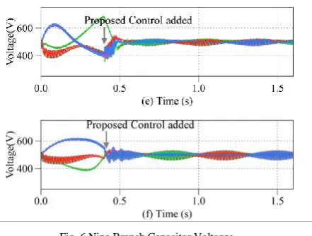
[image:5.595.324.545.48.215.2]Corresponding simulation results are presented in Fig. 6. In Fig.6 before 0.4 s, the basics current allocation is applied. At 0.4 s, the proposed control strategy is added and the capacitor voltage fluctuation is effectively suppressed in ± 15V in around 0.1s.
Fig. 6 Nine Branch Capacitor Voltages
(a) f2 = 50Hz, cos1, (a) f2 = 50Hz, cos0.5, (a) f2 = 49Hz,
cos1, (a) f2 = 49Hz, cos0.5, (a) f2 = 51Hz, cos1, (a) f2 =
51Hz, cos0.5
The proposed control do not apply reactive power at the input side. For instance, under test condition (b), input voltages (grid voltages), input currents and branch currents are shown in Fig. 7. As the input voltages are in-phase with the output currents, it proves no reactive power at the input side.
[image:5.595.322.543.342.533.2]Times (s)
Fig. 7. Simulation results under test condition (b) B. Experiment results
Fig. 8. The M3C Experiment Platform
VI. CONCLUSION
This paper performs a theoretical analysis in phasor-domain to find the branch energy equilibrium point of the M3C when operating around equal frequency. On the basis of this equilibrium point, a branch current reallocation based energy balancing control strategy is proposed. The availability of the control strategy is proved. With this control strategy, M3C can effectively overcome the capacitor voltage fluctuation with neither using common voltage nor applying reactive power at the input side.
REFERENCES
[1] F. Kammerer, J. Kolb, and M. Braun, “Fully decoupled current control and energy balancing of the modular multilevel matrix converter,” in Conf. Rec. IEEE-EPE-PEMC 2012, LS2a.3.
[2] W. Kawamura, M. Hagiwara, and H. Akagi, “A broad range of frequency control for the modular multilevel cascade converter based on triple-star bridge-cells (MMCC-TSBC),” in Conf. Rec. IEEE-ECCE 2013, pp. 4014–4021.
[3] W. Kawamura, M. Hagiwara, and H. Akagi, “Control and experiment of a 380-V, 15-kW motor drive using modular multilevel cascade converter based on triple-star bridge cells (MMCC-TSBC),” in Proc. IPEC 2014, pp. 3742–3749
[4] F. Kammerer, M. Gommeringer, J. Kolb, and M. Braun, “Energy balancing of the modular multilevel matrix converter based on a new transformed arm power analysis,” in Conf. Rec. EPE 2014, pp. 1–10. [5] K. Ilves, L. Bessegato, and S. Norrga, “Comparison of cascaded
multilevel converter topologies for ac/ac conversion,” in Conf. Rec. IPEC 2014, pp. 1087–1094.
[6] Y. Okazaki, W. Kawamura, M. Hagiwara, H. Akagi, T. Ishida, M. Tsukakoshi, and R. Nakamura, “Which is more suitable for MMCC- based medium-voltage motor drives, a DSCC inverter or a TSBC converter?,” in Conf. Rec. ICPE 2015, WeA2-1.
[7] K. Wang, Y. Li, Z. Zheng, and L. Xu, “Voltage Balancing and Fluctuation-Suppression Methods of Floating Capacitors in a New Modular Multilevel Converter,” IEEE Transactions on Industrial Electronics, vol. 60, no. 5. pp. 1943–1954, 2013.
[8] W. Kawamura, Y. Chiba, M. Hagiwara, and H. Akagi, “Experimental verification of TSBC-based electrical drives when the motor frequency is passing through, or equal to, the supply frequency,” 2015 IEEE Energy Conversion Congress and Exposition (ECCE). pp. 5490–5497, 2015.