'IHESIS BY LU'.rCE CHIA-LIU YU!Ji
IN PARTIAL FULFIU!l!NT OF THE
REQ.UIIill.il!lN'TS FOR 'lli3 DEGREE OF DOCTOR OF PHILOSOPHY
CALIFORNIA INSTI'IUTE OF TECHNOLOGY PASADENA., CALIFOHHIA
Different antenna systems were tested for both horizontal and vertical directivity on this wavelength at distances of from 7 to 30 miles. The antennas used in these experiments included parabolic antenna, V-type, double V-type, Adcock antennas, etc.
Using an Adcock antenna the azimuth of the incoming electro-magnetic "'ave can be de:.:'ined v1i thin one half degree accuracy, and with a slight modification of the receiving elements to fonn a horizontal H antenna, the vertical angle of the incoming wave can also be obtained with the same degree of accuracy. The fanner antenna can be converted into the latter by mechanical means within a few seconds and thus both vertical and horizontal angles can be measured with the same antenna set-up.
With the antenna one and a half wavelengths above the ground and with the ground surface homogeneous in the immediate vicinity of the receiving antenna, the direction of the incoming electromagnetic wave coincides with that of the transmitter emitting the wave, witiin the same accuracy of one half degree.
Deviations from the true directions at different locations and at different tUnes were observed.
A simple theory of reception of the horizontal H and the Adcock antennas were also given.
IN'I'RODUCTIO:J
...
1APPA.RA 'illS
{a) Transmitter
...
10(b) ..An. tenna Sys teiJ ...•.•.••.••••••.••.•.••••.••.• l l {c) Receiver
...
15lliEO RY OF .A1'l'I'E:. ~IA. • • • • • • • • • • • • • • • • • • • • • • • • • • • • • • • • • • • • • • • • 28
...
...
...
.
...
33DISCUSSIQl; .AND CO:\CIDSION 64
...
..
..
69lli':IT.ODUC '.i'IO:i\
In the past few years different nethoas have been ~orked out for direction finding at various short Tiavelengths using different kinds of antenna systems. When speaking of direction finding, the defining of horizontal or azimuthal angles of the direction of the incoming elect~omagnetic uaves emitted from a distant transmitter is generally referred to.
~st of the work done on direction finding has been on wave
-lengths of over ten meters. Due to reflections from r.eavyside layers in the high a~ospheres ulone seriously erronous results often arise.
The modern radio direction finder undoubtedly owes its suc
-cess very largely to the introduction of vacuum-tube amplifiers,
enabling a moderately large reception range to be obtained, and ·its practical development therefore dates from about 1915.
Previous to this, such systems of direction finding as were in exist -ence were confined to short-distance working and the comparatively
crude instruments then in use nade accurate syst~tic observations difficult to obtain. As early as 1908, however ,Pickard observed that large errors might be obtained in the reading of coil direction finders due to buildings, trees, and other obstacles in the neighbo
r-hood. In the diagrammatic representation of his results, the errors are shown to be appr0aching 90 degrees. It Tias found also by
of as much as 20 degrees to 45 degrees might be obtained in the
indication of these instruments ~hen receiving over a range of 100
miles. These errors were attributed to a refraction effect result
-ing from the difference in conductivity of land and sea-water, or
even to a var~ing local conductivity of the ground and of vegetation.
In making continuous observations day and night for a week, Fessenden
was apparently the first to observe that the errors were greatest
during the night, a fact which he attributed to a refraction effect
of large clouds of ionized air in the path of the waves.
A method of obtaining an absolute zero of signal strength on
a small frame-coil direction finder ~as described by ~. E. Taylor,
in uhich the "antenna effect" of the coil is compensated for by a
small emf from an auxiliary frame at rig.ht angles to the first.
Using this system at ~ashington, it was found that while readings
taken in the daytime were fairly accurate those taken near sunset
and at night were very erratic. .. ~ile it appeared that the
variations observed on continuous waves of wavelength 13,600 meters
were greater than on shorter waves, they were quite serious on
damped waves of 1,500 meters ~avelength. These variable results
were briefly ascribed to reflection and refraction effects occur
-ring during the propagation of ~he electromagnetic waves over the
earth's surface.
~e liability of the metalwork of a ship to produce a
quad-rantal error in the readings of a direction finder oounted thereon
was first given by ?.r.esny in 1920. Calculations from this theory,
confirmed by experimental results, snowed that the quadrantal error
obtained nay be as great as 12 degrees. This error was sho~n to
be independent of ~ravelength and to decrease uith the height of the
frame coil above t~e dec~. Lttention ~as also drawn in the above
paper to the approximately analogous case of a direction :'inder
erected upon a hill or an island, and the resulting quadrantal error
~hich may be obtained in such a case is illustrated by a curve
having a naximum value of 15 degrees.
The phenomenon of the refraction of electrooagnetic waves
in passing over a surface of suddenly changing conductivi~J was
.discuss"d by T. L. Eckersley in 1920. Experimental observations
nade in Cyprus and Egypt on ~avelengths between 800 and 1,100 meters
showed that ~ireless Whves in crossing a coastal boundary between
sea and land might suffer a deviation of as much as 4 degrees. ~is
deviation falls to ~ero for normal incidence of the VTaves on the
coast line, and it was also sho~n to be negligible for wavelengths
exceeding 2,000 meters. In the paper there is quoted an interesting
case of a bad day minicrum being produced by the reception of two
~aves arriving by different paths and uith a ph se difference uhich
resulted in a rotating field.
Some..-.hc:t sinih ... r refraction effects on ~ireless or radio uaves
Kiebitz in connection ~ith experL~ents on a directional transmitter.
The deviations of the waves anounted to 8 degrees or 9 degrees for
a wavelength of 550 meters.
Some results showing the errors to which a radio direction
finder may be subject due to local conditions were given by H
olling-worth and Eoyle. Easses of metal~ork, tuned circuits, and overhead
wires were found to produce appreciable errors in the readings.
In 1920, Round gave an account, chiefly from his personal
experience, of the development and application of the direction
finder during the war. The manner in which the instrument was
perfected as a use~ul tool for both military and naval purposes was
described together with the various types of errors encountered,
both by day and by night, Reference rras !:lade to the •.rork of .~dcock,
~ckersley, and Wright in connection with these errors, and a brief
indication was given of the raeans by ~hich they might be eliminated
for practical direction finding purposes •
...;. large amount of e} . .-perimental ~1ork on the intensity and
directional properties of the electro-magnetic field rddiated from
an aeroplane trans~tter was described by Baldus, Buchwald, and
=ase in 1920, while a ffiathematical treatn:ent of this case i'IO.S given
by Burstyn. The errors in the apparent bearings of an aeroplane
at a ground direction finding station were discussed in detail in
t~eir relation to the plane of polarization of the emitted waves.
a closed-coil direction finder on the ground could give errors of
as much as 60 degrees in the bearings of aircraft. This fact is
interesting in connection with the patent filed by ~dcoc~: in 1919,
in which was described a means of eliminating the error of obse
r-vation of the orientation of aeroplanes.
Some further observations on the variable night errors
were published in 1920 by Kinsley and Soby. Variations in the
apparent bearings ranginG up to 50 degre e were recorded on wave
-lengths betiTeen 960 and 17,300 meters, and for ranges of ~rans
mission from 40 up to 7500 ... dles.
~o~rds the end of 1920, R. L. 3mith-Rose made regular
observations of the apparent radio bearings of various tr~smit
ting stations in ord~r to obtain data on th~ ~uture, ~g~ituJe,
and other characteristics of the variations of be~rings ~hich
it ere :previously J:ul.o-:rn. to ta:{e place. ~e runge of ~uvelengths
covered in these observations was from 300 to 20,000 meters.
Experiments were carried out to ascertain tt.e el'fect of local
conditions such as metal work, overhead wires, tr~es, ~tc, on
the readings of direction finders. These experir:.en ts sho"'ed that
some quite large errors, ranging up to ~2 degrees, can be )roduced
by the proximity of such obstacles a ~ ~hasize the importance of
exercising care in selecting a suitable site for a direction
find-ing ins~allati. on. The difficulty in finding any approach to an
ideal site was illustrated by the results obtained from the
conditions less than 2 degrees. However, such a type of error
remains constant in value for any particular direction, so tLat
it could be treated as if it was a permanent deviation.
case, the cause of peroanent errors ranging up to 15 degrees was
traced to a long iron plate beneath the ;round and supporting a
sewer duct, over which the direction finding installation was
inadvertently erected.
In l93l, Snith-Rose and:. G. Eopkins obtained an accuracy
of ~2° for Tiavelengths between 6 Qnd 10 meters using loop and
Adcock antennas. The sensitivity of their instruoents was such
that it was sufficient for observations on an experimental 50
-watt transmitter at ranges up to twenty two miles over flat
ground. Their experiments have shown that the site on which the
direction finder wqs used must be clear of obstacles, particularly
trees and vertical wires, for a radius of at least 50 to 100 yards;
and there were indications that similar conditions are necessary for
the site of the transmitter. When such conditions were satisfied,
the bearings observed at distances up to twenty two miles from the
transmitter may be in error by as much as 8 degrees, although in
the majority of cases the error was less than 2 degrees. They
also found that for a given set of conditions the changes in
bearings observed froo d~ to day do not exceed about 2 degrees
fOr ranges of twenty miles, although in s~e long-distance
observations made at a range of 3000 miles the variations in
observations.
Later, H. G. Hop~ins using a loop antenna at the same w~ve
range of from 6 to 10 meters reported an accuracy of 0.1 degree
in defining the horizontal angle of a local transmitter at a
distance of twenty five yards using modulated signals. However,
he didnot mention anything about accuracies at long distances, only
in which erronous results often arise. The loop he used to ge;;
resonance at 6-meter waves was a square one seven inches on each
side. · The receiver was superheterodyne type with a band width
for the 2-megacycle intermediate frequency of 10 kilocycles for
half amplitude, and has a poor selectivity.
at a height of about six feet above ground.
The loop was supported
During observations
the observer has to change position to keep on a line perpendicular
to the plane of the loop in order that he might not effect the
bearings. Even so, slight head &ovements affected the bearings
by ~ 0.2 degree.
So far, no effort has ever been made to ac~urately define
the vertical angle of the direction of an incoming wave from a
dist~t transmitter high above ground.
The object of the present. exper~ent was to develop suitable
antenna systens at 1.67 meters to define ooth the azimuthal and
vertical angles of the waves emitted by a small radio-neteorograph
transmitter sent aloft on a sounding balloon.
One of the main difficulties one encounters in getting do'-U
much below 6 meters for direction finding is the problem of
-factory characteristics. Other difficulties involved in these
ultra high frequencies include: Perfect shielding to prevent stray
pick-up of signals from parts other than the antenna system itself,
lou loss insulation, perfect mechanical and hence electrical
s~etry, possible reflections from nearby objects, high absorption,
etc.
Since the trans~tter has a power output of only a small
fraction of a watt,a very sensitive receiver zust be used in c
on-junction with the direction finding system.
In order to examine the directional properties on this
wavelength of 1.67 meters, different antenna systems were thoroughly
tested for both vertical and horizontal directivity at distances of
from seven to thirty niles. The antenna tested in these experi
-ments included parabolic, V-type, double V-type and Adcock ~es.
The loop antenna was not used because of its small size at this
wavelength that the sensitivity of the direction finder would be
very low.
A constantly revolving parabolic antenna system for deter
-mining the azimuthal angle was tested. Different numbers of
reflecting elements and various spacings were tried. A recording
device operated by the signal output from a super-regenerative
receiver was attached to the rotating antenna. For each complete
revolution of the antenna an arc of from 40 degrees to 120 degrees
facing the direction of the inconing wave vras drawn on the table
angle. The Adcock type oriented for null readilli3S was finally
adopted for defining the horizontal angle. The V-types that were
tried also lacked the desired instr~ental accuracy.
Using an Adcock antenna the az~uth of the incoming electro
-magnetic wave can be defined within one-half degree accuracy, and
with a sli&~t modification of the receiving elements to fo~ a
horizontal E antenna, the vertical angle of the incoming wave can
also be obtained with the same degree of accuracy. The conversion
i'rom the Adcock to tl:.e horizontal ?. type reG_uires but a fe:: seconds
and will be described later. Thus both vertical and horizontal
APPARATUS
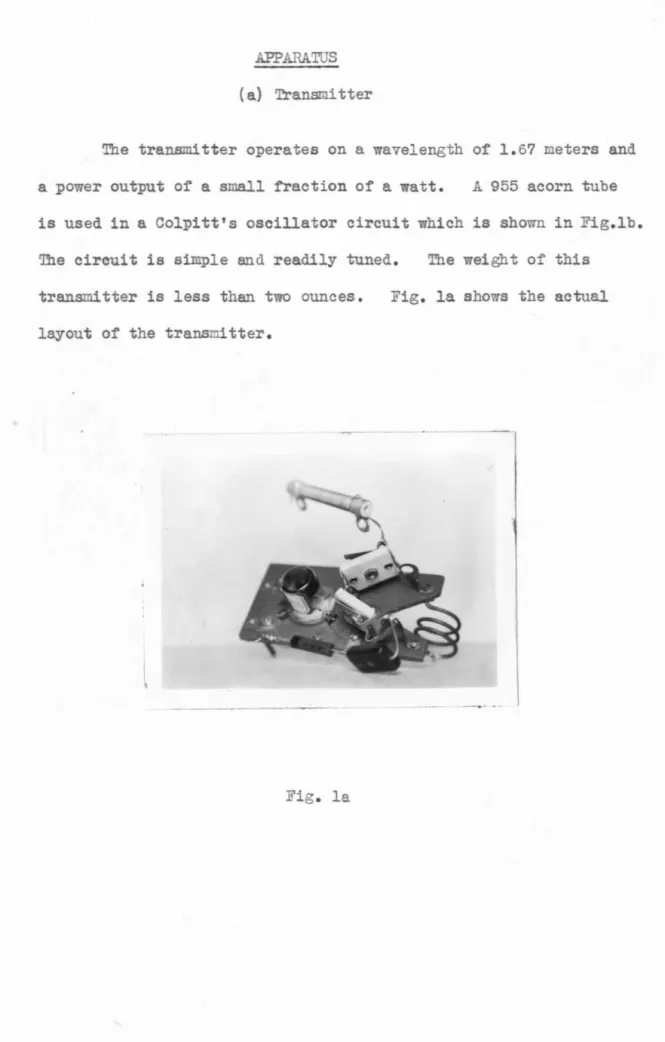
(a) Transmitter
The transmitter operates on a wavelength o~ 1.6? meters and
a power output of a small fraction o~ a watt. A 955 acorn tube
is used in a Colpitt's oscillator circuit which is shown in Fig.lb.
'Ihe circuit is simple and readily tuned. The weight o~ this
transmitter is less than two ounces.
layout of the transmitter.
--
-Fig. la.
h
c
-955
choke
c-15
uuf.A_
{b) Antenna System
For measuring the azimuthal angle a conventional Adcock
antenna system was constructed. It is well known that when the
plane of the antenna system is in a position perpendicular to the direction of the incoming wave, the emf. induced in the opposite
pairs of elements of the antenna are equal. 'Ibeae are transmitted
to the two ends of a coil coupled to the antenna coil of the
re-ceiver, thus giving a null signal in the receiver.
The general layout of the antenna is shown in Fig. 2a
from which it will be seen that it consists of two pairs of aerial
elements spaced at a distance of one-half wavelength apart. The
aerial elements are made of duraluminum rod, l/4 inch in diameter
and 41.3 em. long, and are screwed rigidly on bakelite supports
which are supported by two 1/2 inch duraluminum tubes connected
together by a brass T connector. 'Ihe tubes serve as an
electro-static shield for the transmission line to the receiver. A
twisted pair lamp cord made a satisfactory line. 'Ihe whole
transmission line extends through a horizontal copper tube one
wavelength long and a vertical tube also one wavelength long down
to the antenna coil of the receiver. 'Ibe antenna is supported
by a large wooden tripod which raises the receiver about
one-half wavelength from ground. The antenna can be rotated about
the vertical component of the tran.smission line as the vertical
A
8
Fig. 2
)'\
2
I
r
r
----1
I_
RCVR.
~
I
away from the vertical aria is to avoid any unsymmetry in the
antenna system.
The antenna was carefully constructed to secure perfect
mechanical ~etry. This is very important in order to obtain
satisfactory results.
The horizontal beam can also be tilted upward to an angle
of about 60 degrees with the horizon.
A pointer is attached to the vertical tr~ssion tube
and the horizontal angle is read on a scale on top of the receiver
cabinet.
For measuring the vertical angle of the incoming wave an
horizontal H antenna was found to be most satisfactory, a pers
-pective view of which is shown in Fig. 2b. This is formed by
turning one end of the Adcock antenna insula tor support through
180 degrees, thus forming two half-wave dipoles spaced one half
wavelength apart and connected in parallel. The whole antenna
system is turned about the vertical atis until the plane of the
antenna is in the direction of the incoming wave and the antenna
is rotated about the horizontal element of the transmission
tube as an axis by a mechanical device until a null signal is
obtained in the receiver. The position of the aerial elenen ts
for null signal gives the direction of the incoming wave in a
vertical plane.
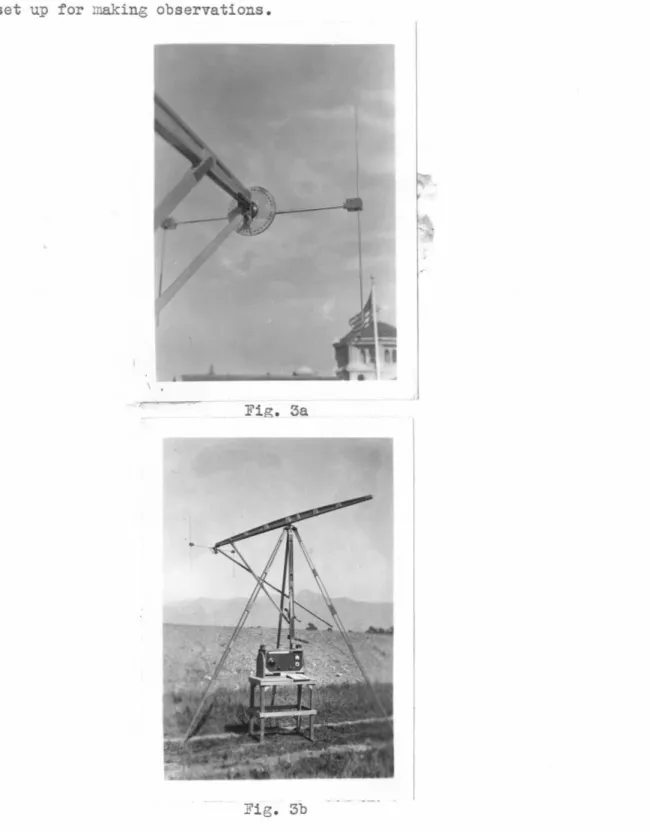
Both the horizontal and vertical transmission tubes are
attached to the wooden tripod and the complete assembly can
Fig. 3a is the picture of the antenna in the set-up and Fig. 3b is the complete assembly of the apparatus in the field set up for making observations.
Fig. 3a
(c) Superheterodyne Receiver
This receiver v:as especially desie;ned and built to operE..te ~~t
1.67 meters for the reception of wen.k signals emitted from c.:. smull
raO.io-mete0ro.;raph transmitter sent sloft by sounding bclloons. Since it v.as
to be used pri~~ily for direction finding at this uave length, st~b
ility in operation ::.nd sensitivity v:ere essentiJ cha:rc:.cteristics.
The super-regenerative tJ~e receiver is ver,y sensitive and
satisfactory for most ultra high frequency pur~oses, but it is not
suitable for ~i:rection ~inding due to its automatic volun:e contrul
cction. L surerheterodyne receiver using a ccnvention:::.l tune--
:.l1te:r-medi~te fre~uency au<~lifi~l is also unsatisf~ctory d~e to the ncrro~
b~d ~~dth of the inte:rmedicte frequency E~pli~ier. The incnnst.:ncy
of tlle inter.a;ediate frequency due to slieht frec~ue •. c:,. v~riations in
tne ultra l~gr fre;uency heterodyne oscill~tor or the ~i~el cc.:..uses
the outrut to ::'luctuate considerabl~·. Thus it is esser~tiJ to have ~n intenr.e~ic.:..te fre;uenc:t £:I:plifier with a fi"t over....J.l gtin ovc:r a ,.ide
h:.1~d of frec.ue ... cies. While this chare.cteristic could be otttintd in
a br.nC.-pu::~ wn. lifier, the sar.e can be achieved with c.:.
resist&..TJ.ce-coupled ampJi~ier, the latter, hoy;ev ... r, is much sim?ler in design end construction . I!l &ddition, it is m:::re com~n: .. ct. .:-~-:c is :free .:'ro::1
. d.salicnnent ci"J.e to the rough he:ndline incidentcl to field observc:.tions.
The receiver consists o~ t~o units, s converter unit and a high
ge.in resist~~ce coupled intermediate :requency &mpli~ier to:et~er ritr
diode cetectors £.rd s.. vacull:!l tube vo~tDeter. The rec.iftL~.ce cou1leci
over a fre :uency rtnt,e of 110 kilocycles t:r. s cllo-:.·int: for E:!'.y elight
var~ations etc. witLout affectin~ the output o~ the receiv~r.
The Converter Unit
The converter '..llit cons:;.sts of c. 956 radio frec:uenc:; 2!!1:;:'li~5..er,
~ 954 ~Yer and & 955 oscillator. The rc:..dio fre;uenc~i e.z1?1 i ' j cr
gives c:n e:.m;lification of appro:xiwc:..tely two ,,nd £. hclf for tre -ta£:e.
The tunine conc.ensers,
c
3 , are !!r·tionu.l UN:-50 cut dmm to tVJo rotorplates rnd one stator plate. One of the stator supports was rcmovec
c.."'ld E~l excess shaft v:~s cut off to reduce the :U.nimum ca.:._ eci t:·.
The rotor brufhes ,,·ere carefully cler_ned and the spring te:lSic·n increased
to give smoother contact. Relatively large trimmer condensers, CT,
are used to give a b~~d spread effect to the t~i o• J~ coils are
one and hclf turns of #20 pnospher bro!!ze ;d.re 1/4 inci1 in aiem.eter.
T':1e length of each coil is about l/4 inch; hoTievcr, in order to mc.tch
the~r inductu.ces slight V&l'iations in the leneths are neces::><:..rJ.
A groundeci F~racay screen electrostatically shields tLe inauctively
coupled antenna coil from the radio frequency coil (Fig.
4)
.
Thepl~te of the radio fre·}Uenc~~ tube i ca~aci ti 'Tel,; cou: .led to the ._;rid
c i l of the mixer stage at the point one-half turn do·,;n from the grid
enG..
The su ~ressor eric of t.c 'Tlixer tube is connected Cii.rectly to
the ;::rid of a conventioncl trio"e o :cill~tor. T~e tap ~ntre
osc'l-lc.tor.coil is r.bout one-hrllf t~.trn up from ground.
shm·.n b;:;· dotted 1; :c;;: L'1 Fi£:. E£., ·:ith the per!toae t.1bef .ountec'
Fi.:;. 4
The th"'"'£ tuning concznsers arc ..;<:-:.gcd to__:E.ther
with P:) ~·eA. :;oG.s _?n.ss:!.ng
through the ::J.ield.s t:.·1s
reducin.:; the back 1<. s! .. ,
hi8t fre:uency lo~ses,
and !Jarticul;-.rly the
interf.tage cou~ling to
a minimum. Vihile clJ
three rotors ,..,f t::e tunir..2'
are £rounoec, ~nteretz..ge
coupling results i:' c. com.'!1on
s.tt...ft is used.
con::=.:..derc.t:: o •• ~ re .. uire
universcl cou1lin__:s between
these conde~sers. Even
though i solo1ti te n1i •rer .::cis
· re. em.loyed tn ·.s i:::;olftin~ the rotors electricall,, if metc..l shafts
rre u~ed for g&nging, et these ultra high frequenc~~s enOU[2 enerGY
.J..S tr.-.nsmittec through the ~hields b~· ttern to ~rocuce indFl.ility.
All fil~T.ents, ;ln.tes ~a scr~en grids of the three tulee cue
isold.ec ,..r)~ t1-1e e},"ternal ci:·cui tu b:; c:10kes ~'1.d b:r-::'ass conde· se~ s.
Smr l :icu ccnc enscrs Tiere built into the tube so~kct.: for ec.ch ele~ent
sup~ lcn:er~ted b r lc.rce ccnder..~n·~ cmmected in pr..rellel for m2.Xiuum
bypEssing Pficiency. Chokef' in the high voltage circuitE are
desi~led to be resonant ~t t~is particulEr frequenc~.
CONVERTER
-·~··.
'---:::0
..
-
::~-•
Fig. Sa
C.~!IO.,..a..._
C, 1!::.~\:... Sl* . .
... , '"'
c. Ml!-1 "'"50 c..·--,.lP*I1n·Mt' .. .
C.~T-... )0
.. "'
.
.
~&~6 the ~'-pass condensers at tbe heater ter~nals 0f the tube
rockets cor..f~rc ~y ~trc.y radio fre~uencies to the resrective tube
circ_,its.
In order to rec. 1ce the noise levr,l due to microphor..ic ona tube
noises cioy:n to ~ desired !!linin:urn, the coupling conc'en::er,
c
2, to theinter:nedia.te fre'_uency [.lli._!:lifier must be very sP.Jcll.
c?
condsts oftwo wires 5/8 inch lone Pnd /2 incn aiJr'rt (1, 16 ":i :-e) hie::: is
P I "
S'J.!.J.l-cient to .;ive the desired coupling. The whole conyerter unit is ::lo .. n
:1. •• Fie;. 5b ~d :c , ....-hile Fi~. Ed shov·s the botton viev· of t!'le ch<..s ·is
Top vieu of converter unit.
Fig. 5b
Si<ie vier. o: converter u.ni t.
Bottom view of chas~is of converter
Fig. 5d
Intermediate Freguencv krr'=>lifier
The inter:nediate freque .cy a.n •. lifier consists of four resist~'1ce
cou9led sta~es. J..n 1851 "!d two 1852 high u television [!.Inplifier
tubesdrive e 6J7 in triode connection
(Fi
e
.
6). Tl-Jis r:-_:1lificr isce.able of delivering .even inte~eCiate frequenc r volts to the cicre
before overlo~di'1z.
The overall B.!llplificn.tion of this a.•zr;:>lifiPr unit is <:
roxi-.JL;;.tel~ llQ,OJO rt 220 !~ilocycles. The response cu_~e of the unit is
flct from 150 to 260 kilocycles r s shown in Fig. 7 , •;hicL is 11lotted
v.i th the volUJ,te control so set tL .. t the amplifier is d the threshold
•
..
.
AMPLIFIER
Schem~tic circuit oiagr~~ of the I-F
amplifier ~~d the detector unit.
30
I
I I
FREQUENCY
CHARAC
lrt!..!iRISTICS
OF
I
.
F
.
AMPLUTE
~
/
0
u~
I
//
I
I
}
,.
Q
2~ 15
"
l
~
I
~
I
I I
I
1
20
a
r
~
p
I
i
f
i
e
r
a
f
n
u
i
:
~e
t
hreshol
d
_
_..
!0
-Qr '
-1
5
100
2
00
Kilocycles/
sec.
j\),
40()
500
I
I
I
I
I I
I
~·
I I
~
)
I I
I
i
II
~
I
't
~
I ' I I
<
I
7
l
'l
i
etector &nd Vac~um Tube Volt~eter
~ du?lex-o~ode triode, 6F7, is used as the conb~ned &nd vacuum
tube volt""~et r. One of the double diodes o~ the 6R7 is cou~led
directly to a phone plug, ;·hile the other is coupled to the zrid of
the triode section "'"hich serve~ as a D. C. emplificr in the ve_cuum tube voltmeter circuit.
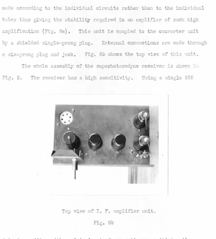
The intemediate fre~J.ency e.oplifier end the detector end vc.cuu:t tube volt~etcr are built as one unit. The chasses and shieldf of both units rre built vt'ith heavy cop~~er sheet Cr're.iull · .:'or.ned a11ci
solcierec to elininate hig~ resistance joints between shields cnc
c!-.assi. s. Shield.., enclose those netal tubes ~·hich have grid ca_?s on
top. Beneath the chasds of: tr.i.s .mi. t shielded com_ art:tents c:.re
Bottom viev o.: the chass~s o.: I. F. e~pli~ier.
mcce ~ccordin~ to the individual circuits rather tnan to the individu~
tu e::: tl:us giving the stability re uired in an e.m,lifier of such high
E..!!!plific~tion (Fig. 8a). This unit is ccu?led to the con7erter .nit
b~r <... shielcieG. single-prong plug. Exte!'llcl. con .. ections ere rn.::.de thr::mgl~ Fig. 8b shov:s the top vie':\ of t!:i:: '~'1H.
The whole assembly of the superheterodyne receiver ~s sho~ ·
Fie. e. The receiver has a high sensit~vitJ.
Top view of I. F. a.1 lifier unit.
Fig. Sb
tube trensnitter v;i th a ~,l<:.te input of one v;att over ~ thirty-!!lile
optic~ ~£th, the signel is strong enough to develop un internediP.te
:re_uency voltage of sixteen volts on the plrte o~ 6J7, ~.e. to opercte
Superheterod~~e receiver
Fig. 9
The frequency range of the receiver cover~ :rom 1.64 meter to
~bout 1.~8-~etey ~~d spre&ds the bund over the EOO divis~on~ of the
E&tionW. P 0 dial, whereon each clivision represE-nts a fre. •ency chznt;e
of about sixty three kilocycles.
Tle tuning is sharp and smooth ~d no ~ore critic~ th~ average
broEdcast receivers. The calibr~tion and overall perform~ce re~ain
very const<.::t through the vc.riations in tempen.ture and hum.idit-,
nne
rough handlir.g enccuntered in field Ee&sure~ents over c.n e)~e~dec
period of tilJ!e. Tbe mcx· ~ variction ob~erved due to the combined
chc.nges in the transmitter and receiver is not over one-l .. .:.lf ,.:;ivision
10
(/)
5
0
a} .p .--1
0
I>
l'<:i
I
H
Q ·r-1
.p
; j
E'
g
I
(
SIG~
.AL RFSJ)CJ
'SL
OF
RECEI-VER
Fig. 10
Signal Input
FizlO shows the signal re:::ponse T.ith the output in intcrmedicte
fre1uen~J volts plotted as a funct~on o~ signal input, for oifferent
settings of the gain control~ The i~put was measured by observing the
anta~na curre~t o: the trDns~tter used as tne signal source, the
trensmitter end receiver remaining at fixed positions curing the
o bservetion s. Cu..."'Ve A sho'?l's the linear characteril"'tic::: o~ the con-verter end & .. :·:1.lifier &t c.. lov; ~ain setting. At r~gher gain settings,
c·rves B <:.!ld E shov.- the increcsing effects 0f ~"verloariing in the latter
stages of the intermediate frequency amplifier c..t higter out~ut levels.
In curve E tbe gain VTas set for the threshold of noise. Curve D is
for maximum gain and shows a very ~teep slope at the region of lo~
signal input, so that c.. slight varic..tion in the neighborhood o: zero
sit;nA.l procuces a great change in the output dgncl voltece. Since
tte receiver is prL'1arily for C:irection f'indinz b~· a null point ~ethod,
(a} Horizontal H antenna.
Consider the H antenna as placed in an electromagnetic field,E,
of a half wave radiator. The electric field strength in volts per meter
at a distance r and at an angle
'.JI
from the center of the radiator isgiven by the expression
E
= {,O~.
cos(.Jec.stJ!)
Si11co
(f.-L)
r
.s
~I)!,'V
c
(l.a)where i0 is the current in amperes at the center of the radiating antenna.
This is the magnitude of the electric vector in the Jlane of the radiating
antenna and in the direction perpendicular to that of the radial vector
r . Writing in exponential form we have
£
=bO
~
co
s~~V)
eilf>(-t-~)
(imag.r
s~-n.,Y part) (l.b)Let the E antenna be in the plane containing r and E and be til ted
at an angle
9
from E, as shown in Fig. A. Since the middle partsAB, andCD of the antenne are well shielded, any pick up due to these parts can be
ignored.
The emf. generated in a length dx of
the Wire Aa at a point X from ~ is
Exdx
cos9,where
Ex
is the field strength at the pointx. Since Aa is one quarter wavelength
Fig. A long, it is necessary to take into account
the variation in the phase of E in calculating Ex. It is seen that the
phase factor a distance x ~roo A is given by ej~x sin9. 'Ihere is an
additional phase lag before this ii:Ipulse reaches .A alone the wire given
Since the reflections from the upper end of the wires depends
also neglected. Hence the integral of the product of these terms along
the wire
by
gives the total effective emf.
A
E
j1f
b
0c:.
cos(:fc.oslf)- A o 'r ,s;..,
'If
Thus the potential at A is given
eJw(t--¥)cose
e}
~
st
"l8
-l)
~
(2.a)where r0 is the distance from the center of radiating antenna to A.
Since A/4« r0 , therefore we can write
b
0
_loccs(-f eoslf'J
~f, 0
i. CAS(-f
tostl')
=k
r
.sin'/'
Yo
St"-rvif/
-E A =
I<
e.
'
·w(i.-lA) c. CoSe
j_
04.
e
j~(Si"Q-I)xd
X C)=
-j~-si~'~B)J<
eiw(t-i-)
CPS9
[
r-
ejf(sr~e-1))
(2.
b)
Thus
(2.
c)
Similarly the potential at 3 is given by
t
=-.
A
K
j[w(-t-~)- ~·~l41S8]
e[t-
i/(shtB-1)7
B
:J
~(l-sih8}e
eos
ej
(3
.
a)
since
Ex
at B differs from it at A by a phase factore
-
~
ABcos
9
or.l;r>..
6
e-~cos ·, and Bb is parallel to Aa.
The paten tial at C due to the induced emf . in Cc can be obtained
just by finding the potential at a for the element Aa in the above case
only 'l"'i th an additional phase factor in the expression of
Ex
of amountjvr >.. •
9
:rr .8
7\te -,c"+s~n or e~sm • The phase factor at a di stqnce ( 1 4 -r) from
a is biven by
e
-
J
~
{
~
-x)sin&, and the additional phase lag be:'ore the.fVr(~ )
impulse reaches a along the wire given by eJ 7-.. 4 -x • Thus the
paten-tial at C is given by 1~
·
,ll. {t-lR) jf Sin
e
8
~ j~[(t-x)(f-soz
BJ) JvEc =
K.e.Jw
e e c.ose
a~__ · ?\
u
iwlt-!i-J;:isih9
Jfft-st?t&Jfi_
i-I
r
s
;
>ae-~7
-
J
~1f(J-si,.,8
)
"e
ecos8
e..
L 1J
r.:
'
.1!-[
·~s· &-1)1=-j
M(~si11.8)
Ke-iw{t-tJcose
e'~ t
-
e!~
''Z j {4.a)Similarly the potential at d
~
=
-
J
·
A. .ke{w(
t-
t)-YrCo.SO)
~
~
o
S
6U-
efff.Sihe-t1
(5.a)1> 1Jr(t-Sv11 8)
Now since the antenna syst~ is ~et~ical uith respect to F and
The position of antenna at8 =~~ives a null signal in the receiver
since ~FG-=0 at this position.
The converted values of gF~ corresponding to tre readings in the
output meter is plotted against
8
as shown in Fig. llA.(b) Adcock Antenna
In this case the electric vector, E, of the incoming electro
-magnetic wave is parallel to the antenna elements Aa etc. Let the
plane of the Adcock antenna make an angie rfwi th the uave front as shown
in Fig. B.
Top view
£
~
A,a
Fig. 3
Side view
a
A
c
c
F
1+----72.---..1
The potentials at_, B, C and D can be easily got from (2.a), (3.a),
(?.a)
(?.b)
(?
.
c)
where
4>
is the angle i7hich the plane of the Adcock antenna made vrith the .br A . _..s..wave front, and e-J~~s~~ is the phase lag of E at B from a.
By sirailar arguments as in (a), the r .... sultant potential difference
across FG can be written as
(8.a)
We see that gr~== 0 at
cp
= 0, which is a null point, andg--r:c,
is a maximumat
4'
=
i
·
The converted values of g;=~ corresponding to the readings in the output meter of the receiver is plotted against4>
as show.n in Fig.horiaontal angles is shown in Fig. 11cwhere the output meter
read-ing, i . e. ten minus the signal output in the receiver is plotted
against the azimuthal angles. It can be seen that the direction
-al response of the antenna is very sharp at null signal. Fig. 12A shows the directional response of the Adcock antenna lying
horizontally for vertical angle measur~ent. Fig. 12B shows the
directional response of the horizontal H antenna used for vertical
angle determinatimn. The latter has a very much sharper response curve, as can be seen by co~arson of the two curves. The
characteristic curves were made uith the transmitter at a distance
of sevenmiles from the direction finder.
With a small transmitter on top of ICt. Hilson and with the
direction finder in open fields at distances varying from seven
to thirty miles optical path, both the azimuthal and the vertical angles of the incoming wave can be determined well within 1/2
degree and possibly 1/4 degree accuracy.
~ith the antenna one and a half wavelengths above the gr6und and with the ground surface homogeneous in the immediate vicinity of the receiving antenna, the indicated direction of
the incoming electromagnetic wave coincides with that of the
transmitter emitting the wave, within the same one half degree accuracy (Table I) .
Asimuth of j nco:ning wave as
determined by direction finder at repeated tioes in degrees.
0
0
+1/4
-1/4
+1/4
TABLE I
Average
in degrees
+1/?
Azimuth of transmitter as determined visually
in degrees
0
(Observations nade at a different date but at approximately the same location)
0 0
-1/8
-1/4
-1/4
-1/8 0
Vertical angle of incoming
wave as determined by direc
-tion finder at repeated tines in degrees
Average in degrees
Vertical angle of
trans-mitter as determined visually in degrees
+81/4 +8 +81/4 +81/z
+81/4
+81/4
(Observations made at a different date but
at approxi~tely the same location)
+?1/4
+
?l
jz
..-71/4
+8
+8 +8
from nearby hills or buildings that mi§ht interfere with the direct
wave, a rotable parabolic reflector was set up at the transmitting
antenna on top of Lit. Wilson. It was found that change in
direct-ions of the inooming wave appreciably (Table II).
Experiments were also ~ade by tilting the transmitting
antenna 45 degrees from the vertical. When til ted in eight
different directions, both the horizontal and the vertical
direct-ions of the incoming wave remained unchanged. Although the tilt
produced a slight decrease in the received signal strength, the
sharpness in deter~ning the directions is unaffected. Thus
for a considerable swing in the transmitting antenna through
an angle as large as 90 degrees both the direction of the incoming
wave and the sharpness in defining the direction are not affected
(Table III) •
Apparent horizontal deviations of the incoming wave from
the true direction of the trans~itter were observed at different
tilts which the plane of the Adcock antenna made with the vertical.
Horizontal deviations at different dates and at different times
of the day were also recorded. The results obtained in a field
at Lombardy Road are shown in Figs. 13-16. In Fig. 13 it is
seen that at zero tilt the variation in the horizontal deviation
for each run is mostly less than one degree, although in one case
it reached one and half degree.
The site on which these observations were made was covered
Position of transmitting antenna
{reflector position)
Ill
§
(.
Q)
.p
~
~
c
..-4
I>
..-4
Q)
0
Q)
~
~
u
)
~
TABLE II
Azimuth or incom
-ing wave
(in degrees)
-(1/
8)
-
(1/8)
-
{1/8)
-
(1/8)
-
(1/8)
-
(1/8)
Vertical angle of incoming wave
(in degrees)
5
4~
4
4~
4
4 ~
4
4 1
2
5
1
Position of transmitting antenna
(1) Straight vertical.
{2) Antenna tilted 45°
from vertical pointing in
the direction of receiv
-ing antenna.
(3) Antenna pointing 45°
from dire~tion of receiv
-ing antenna. (anticlockwise)
(4) Same as (3) but 90°.
(5) Same as (3) but 180" •
{6) Same as (3) but 270°.
(7) Same as (3) but 315°.
True bearing.
Azimuth of incom-ing wave
(in degrees)
3~
8
3 1 4
3
3
2 7
8
31.
83
0
Vertical angle of incoming wave (in degrees)
3 1 4
31.
83 3 4
3 3 4
4
3 7
8
7
*
This series of readings was taken following a rain while thenorth-west of the direction finder. Evidently the tree some
ef-feet to the horizontal direction of the incoming wave as can be
seen from Fig. 1?. Rhen the direction finder was moved twenty
wavelengths west, and the tree was aLmost in the direct path or
the incoming wave, much smaller deviations were observed, and
the deviations thus obtained were of opposite sign as in the four
other cases.
In Figs. 14-16 it is seen that the horizontal deviation
is at a maximum at about thirty-five-degree tilt.
Fig. 18-29 show similar observations of horizontal deviations
at different vertical tilts made on the roof of East Bridge Labo
-ratory. This site is surrounded by many other buildings from
which reflections of inooming waves were expected thus the hori
-zontal deviations observed were wuch larger than those observed
in the field.
Similar observations made with antenna at different heights
above ground are sho'I'ID. in Fig. 30. It seems that the height
or
antenna at a distance not higher than two wavelengths from ground
does not affect the shape of the deviation curve. Due to
prac-tical difficulties antenna higher than two wavelengths from ground
has not yet been tried.
Observations with antenna elements tilted five degrees
fran vertical to form a double-V both in forward and backward
direction were also ~ade as shown in Fig. 31.
direc-~"'»_.S:.F' H 06 09 OL
0'
os-o!r'
or
Ol: Of 0 01-Ol - Of- ov--o~-o'
- OL.- 09-
06-hi
:
''
!
1.~
••• 1·+···
·
-.!i~H
··
1··· ·. -,. -·t+ltt+:t.t.,-:.: !I-t •· .• , ·l··! ' ,I. " •• I, .. r • • .,.. • :r.~ •. '!·td-r' "t ttt· .ut..,....
-.-· .::: r:-~-...
_,.i
;'Tr ....,.! : · _,tL~ • : ::t i•T 1'-. ~~:· · ~ -~ o-t-'-4-1'JI"'
~J;~+P:! }··:tJ' '!1·, ' f I l • • ' It • I • ' ·"' 1-J t I: ~ ].!_.; ' • l"-~ ' + I . ..-..l--!-.. t t-,_. ; t ~ ... t • ,.. ·~ ~ -/ I ' • ' • t · --... ~ +-+· I ·:.;-::.::.t··, .. ;t "\, ~~ ... •w •. : l ••. : J:.1"/1("
ttt,.,t!;l l: .t -r+j~"Jf. · i-.l~ ,,_. •t-t ... ·•t • t .,... "'" 'j• 1, · •i • :! ~-~~ ~··-~ ''J I • t f· I f+ft J'f~ ~.., ::t:::-r~..; f't"•t ,.._!.J..._~_t-{·ot-1•-t I ...,..._ ,.. ! '--tt '-.. ~""'-f• i I ; + , • tt,t tt-~t • · · , ... . . ! -t-+---'4 · i · •• -_ t i I ... .• • • · ~ I . """ ;·. '{ · ' . .,Y
,r
·~-t.I
·~··.
.
I l .• i, +. .•··J·
1 · t I . I. • 1 ' ' i 1 1 ' I \ . . . f ; I • r I I . . rl . ' • ,..J .~ ·t .... 1 · 1j' I I I : -I. 11 tl . r•. ; 1-hr '':I . ' . t • · • ' J · t r· 1 • ~ ... • -t 1 r-l t · · t -·t t t 1 · 1 t t · • ~-t · -+ .... . --!..LL..I
.
·
•
;
tJ ' • \ : .i l • J. 't. t • / , , • r. ~ · • i: ~j~ I It •1 · ;
' .ij • -11 r ·; 1 ·
'i'
t I 1 11 ,j
' 1 ~: ' "•' -• 1 , I ... ~ ~ ~ r _ I t 1 .,. "' • : ~ I 1 -• -r- ·-' t 1 · l I .. ___;. .. - ~-~ I -_ • ~ : ft... • -t • -• . ~ t-it I • r ' -• :,_. • -
•-
---r-.
+' . . . . I --. • \ I [-1 • • . • ' { T • ' • . -. I ' ' ' • ttJ. ,1~ ' l ~ .. ~-... L +o. • ... j • t -"1 ~ -, • ' :} ... r t-t ~ ~-.r' ~ t I. ~ J-. 1~-i . --r.r I·
I • " ' 1 · · 1 ',. • 1 , j "' r l · i ll '+ ' • 4 ; I ' ! , H t-t (d'+ o-+, __f~
.~:
L;
~
~·~·
::
k:
:til
~:·.
::::
~:
i
I ::-~
i•
l ;l\
i ..
:.·I!'
~
R
L
l
j
m
jf
~
t~
~
-~ :-~
_J~
..•~ A1~
'j+. --_H1iY
'
IH1
i!~_tl
~~l~
I
Bd
l
r~!~
J11
mr:.
i
I~+_:{
41i
l
j,·.
.j
:
! •. ; ~ . t i-r1 ~I
t • , \ r :-J I ~ L~ -~'~·-~ I t ' • l f . !J ' l j -I . . I J:L ... "l
..
t: I t ; t i1 f~-. • f ~ t:l ~f
h ir t t f ~ ' . . .dll.
~ ' ~ -1· I I • 'I ~ ~.. 'l J t-!1 ' L ' 1 1-l+ • Ll • . t ,I ' 'I . 1, ;l-..j '1--L.:t
I • • •fff!
-. -. .. .. . . . :: l ![_ • ' Jl I' 4 ' ... , ' I,,_. \ , I j ~ar
Lt .. II ~t1J
4 '' • . 4-~t r : I . J . rl ±~ 'T L T 1 -fi't.t i+lf ~ I ·, ;, i.~t '1 ,,~, •· I ' l iT - ·~-J I I' ! J 1!1~.1 ~ 1 1 ~ 'L-lL[I '--t+-l~ •. J-'l 1 l! t ,. "tt-l ti-f 'F~f l fi11 1 ~ltl ~ ~ 'fir I ~ht 1- -:i·-:--•. ;...!: • :T 11· 1 l{ ...~·
1'1 il-..:-i
,,
-I tr+~-fttljl
0
~
tt' lH )Itt r..t l·-~,-~
.L 'l' trJLI r'iJt ±llt!i:jJti,UL ji·IJ t..,• ji1 1 i-· 1j-~
i . ' ._ • : ·:--r . • . ~ .i-1. t ' ' ' ;'~ '-1 ; · ~ I· 'I ttf!l~t f.l Lf. ,ht 'Ill 'TJ" I I '-fi:!-~ :.j, :r. l·; .•. f-1-t-1 1 1. ;n i1 !~W 1 .t:.: ,;nr
.,
J l \-, 1 t lnJ·--_
...
l .11 t-t·• · '"''!"'''' ~ 11 tci" 't l ·! ~l tt ' II• ·+ -•, H·l--1 ++1-jrp l ++'•it''-"'lt'"••.•+•4''+-1-J-1
h·"':!_t ~~ ·-·, . 'I .. --~,, 1 .... , t·· fl!' -r, ~ I' 1 '---' · ~~~ .. "-t 1·~--' .. ~L n __.J. . -. ·-t-··t r1:_: 'Ji ~-_'_: • : < :. --1 '~ -i t' f .L i ' . " i '. I . I • \ ' . t ' rd:t Lj + ~ ., " : t . ~ --: • ;·I ! ':j j -.. ' ; I • J i -~ . 1 ' '-r
l
.,·. ''''4-i'
.;,
:
\
,
~ ·...
j'+ +h':f,~-'' t '-~l',,
·• -'f ·4 . ,.···.t
..
I I ~~ t .. +t fl f-.• lt••• I -~ Oro t. <· ·tJ .t._.__ tj. ,..._,. .. ~· t · o& ... . ... • ... ~] ,J 'h I t-Il .. I ·ti
Iff-.., . .• • ., .. 1 ., •:-11 ..
-··-,1 1 ••• ,_ 1 , ·; •1 •.. , ·-+-. , · ;
1 •••.
, _ . -·H r·,.. 1. . 1 ._ I ,._ 1 .j... .. • .. I, ~ l T t ~-I 11 I f t t ·t·t -n--H 1· ... ~ t 1 I t j ~· I ' -1 '1 ~ • .. I •
+·'!
...
;
..
·
.
,
·1 · ' ~J.;;,
;
1;+1
tHt, rl t;;r ;~·. •· ,'{i l tlj l 't ~ •j'.Jf'
·t·l
,,~1:-ln'j ..f.,j.:
-1.1-:r·:.EJ.
·;~~ · 1 1 1.JH
'+:_t ~~. I P _ d :1 1 •1n
lij•:t:r1 __
~ . '! 1 1ti. -1-H 1 • t ' l•+t j It It . 'I j +f .f', .1· ti l I '11 q ••• '·· ... 11-t ! rl-t r '~T ... -1 F. trtt t' .. , 114+'4-1 -~~-~-4~~~~~h~~~·~~~~~ ~~~~~ ~ +-~+r~~~+--+.-~~--~~ ~ +r.-+~~~r~+r-+~~~~ .·· . !'
:.r;
t·1-:.:Jt
'
1 ' r~.;
~·-j.
iI
'
11 •• I I, j,:r:
:-t;:t-t~t~ l r : r' 1 -m,,liH.
l1.
_
11.'
tt t+'L-!·: 1 '_l
'
_
..:--itii
1 ··1 . j .... .;,<; l~• , , .... uJ .. l-'+,! ~ .• r,.,::t~. 1-.<j::::j:r,J-lL1. 1 c r.Jt 1 ,,,~
1=~-~~-r
.
1 . . .I . . . .. 1 . • . , • I ~·~ ~ 1 I . . . r-;··.+
_
~r·-1
t·"tt
fl·u l ll + ~j
rJ
J,·t··
i
fm'J.
tt:$::..
_
-· t ' ' + · ' • " I j ' 1 't 11 1 1 II . • I · ! 1 t. 1 • · • I • · : · 'J l t l1 1 PI • 1 l·r' --r · 1 1 1 I • +: • -t• • t·= it· I .... ;-~ .,r.. ~ j_ ,_t • ].~ I • T • ! 1 l t-H+• 0 l ., . . l . . 'l •...ti , ·ttH . 4 ltl . _. -1·:
!-:-;:
.. -::'
.
~I
~
H
il·,
.
1:
J
tl
'
t
l~~IJd'
';:
lrl; :: 1.tt
1: / , ':'~
~~i-j
T.~
'.· .. :.'·t~
:'.~·
'Jil
ili:
11
1l:
1t!ll.
n
..
Hfll:tll1J!'
1,~
(
Ull
! , ._ . + .. 1 , t 1 , • t I I ;4) , 1 .... o L...j • J • · ' 1 r, 1 ' • i':--; + t t 1 _f. '.. • ' • • • • J j ., ... • I ' ' • ,· I '"' : . + • ' ' • ' • . • : • • ~ •1 ... ;--1 ., I.tt
·
I ' ' ' ! J ' 1-r ' ' • • • , I ' -• • • r ·-_ _._. " 1 I ' • • · II , · 1 .. 1 ' t-.-t 1 ~ II ... ,--:;-; · _ .; t·• • ~~ t-t ~ -. , r -, • .. ... , • • 1 • • l.. 1 ' , ~ 1 t _J • • 1 • _ ~ 1 -1 . • .... :·· . • . . , , , ~ .. t . • _ . t +. . •••• • ·•• • .. ,· i ... 1. , J1•' .. ,~
.··
t
,·.
i, 11 1 ., • , . ,, • 1, • •~~~
.!:--.,.
·
·
1··r
.! • ,·
~
l~11
.tR·Hf~f
1 t • • ~ • • I 1 \-' I TT r t I 1 ! t f ' f t 1 T ~ . • • • • • · •'• • 'l ' 1 -•'" if l f•f111 t ••-• I~ '' 1 ... t, t , ... ', ~i~+ r ~. ' ' j... 1 ,1 IJll ijf~-lt t, .:!;~ 1' _+.
..
.
,.
'
I ' " I k • -r.l . . + ... '1•. +H-.... ' ... ' : t 1" 't t .l- '-... ' I ""f 1 t I t • • • ' I t t ; t-I t .,. • l T ~ ' ' t ,.... t.,;...J. ~ + ' ..,. ' ~ .. .., .. ., . . . t .. • • ~it-"t··t· t t l .. ..o...l ; i -.. t' t --:-[----... I • .__._ .. -t t-+t ..._ !-'---· · · ~ .... ...ru··
I . ' • • I " • • . T ... I H • • • ,· t • ..rr-_
..
~.
-.
tl -rp •to:. .I . -. t • : . lr•
:
l i l 't • • I :-r :~
I f -' ' j I • I I~
j , '·t! . ' I t -r 1 ' I ' J ' -r : I~
It~
. I • ' • '!j ..l
• ' -I I • + ! l -:__ 1__ I I ! I _l _ "rT 1 1 ~ t , . .'
.
.
~!ll I ' ._ d ~~ tI
.
i l; jl•I r4 . ' • • ;· 1.' -, ·· , . -j•·' ,,.1
1
,·-·'
T;il:
1
,1.
;r:-·.~
l
to..~~n-lr
....Joli.
t
n,J
.
~
~.l_~J.
1
-
)>11'
11
!Jl_p
~
~~
l
li.r1.
11•
~
l l'n1;..;!
..
Jl
1!1
+_,,·i~"i-7-1t
1
1_
·J.~f-4..
_
:~~
---~ ~ ,_.... -L !J"Ll~:'4'"' 14 -r • . '''I l" II t •• ' J. • II' . 1 \t'O ll i~i '•t
;-'F 'p·r:
~
b.,.
·
bt
l
2'-t-.
·
'Md ·l.
l
~,~wbo-r ·:~~
•u:
t-
~-·
~·
1 ....~
• • _.:, '.~'It
• · ••~
:
·~
; ..':H
:~~:
.:·n
.
I ' '1 I 1-. • + • • • . J • ' , -. L\ '1' I ' +t,.i ,. • ~-H t ·=-• -.. ,. -• • tI
I . . • . • ' I ' • li r . ·, ' : .. J. ~ • • -~ ' tr. I • r•+ f... • ... -1' I •·: f !t~ -I I • ~ -~ I Lbli.J 1 !\1' •, -. .., 'I ~~· 'r : · t<~t -tf~ · +1~ -· ,_ __ --~~--.1.. tii0~ +-'1Jr~ -:r- T-•J{
j •. · IJ ' ... -r1
~ ·, ,.,. • . • .. , ••,11-1 t-J..l' J • .1 Jj1~ .• ::· ,,.I '
..
·I
".
~NQI..J..I~ 0 FI lf.'L'"'N , ~~~~ r'1 . 1\r~ : . . .1' _ ' ~fH
'tl.t ,' ,i' .;, . t ... l···r't :J '!! lj., l ~,y r,ll . 111 j T'•:.r~tt~. ~~ • • I. j t ~ l-• • Ll · I I I r• . . . I • .t'
it~ r . ' I ? j • l • I ' I ' ' r + 1 , 1 It· ...
!'
·w
3SP!Uc 5~~~
a
t
.::tn
j
L:IP-:1~
1.
lj.f ,+_. I , ••'it
I I '. ' ' •l'
-,
tt
~I
i·.;
'
+'t'l
·_
.
...:t !-i-l;'tH~i
..
I . ,I
.
ah
1 ·' • , 1 1 ,11
,
:.
..
.
.
1 ,J
.
.
.
,_
.
r, 1 • 1--• p , • 1 J., . ·~-t-j_~
-'~
f:
-I · -• • ' -• 1-• I 'l' -ji 1 t~
:It" 1-
1-"r
Ir~r
:
:
~I.l
'!''~J..t.:;rtr~
~~~~
~
.~
,
·
-·
.
:-:~:
r::~
-i·-~~~~~:
~
·
H;-4r.
11 •+
lr-.,
.
~
r
~'l!
.
\
1
-;
I•
-
-I
.
I I·
-
I
I
-;
.
.
-I
.
1
-..
1-~
N
i 0
N
..
(533~~ 3.0) ~011 ~IA3C 1\1.1 NOZI t!O H
t-I ...., - f
_:::1
.I
-~ ' ,..__
...
I
~~~
. r
[i
: - - +
--·'
~ _:
-' ...
...
~--
~~~~~~-+--r-+-~-H--+-rr-+~r-;-~~r-+1~-4~
..-
~.
+-~L-.-+-~-
~
~
~
4~~
~~:
_
~
-
-
~
~
~-
r
~
-
.
+r~_,~
·
~ ~~ --+-~~~4-++~~·-+·~·~~~H--+~+-~~1-+--++-H~~,~- ~~~'~•*-+~-~---~-+--++~
I
a
r . -~:I - . l - - ! .; . '..r:
~:
~. I~13
.:
t ~~~~~--~4--+-+~-~4: ~._ -._-~:~--~4_ ~_-_.+_-:-.~+-~._-,~;~1+-~~---~-:4_~!-~~~.~.r:~-4, +_~~ .. ~rrr-4r~cU-T __ +.-.:-1~,+-~~~ ~
~u.. .:::r::-. !.~.:-. . . -~-- .. .;r_~ ··.t ~r~::± .,.. r::' :- ..:>.
..
-·
-~--~; 1-- __ - ·
~4--4~~-r+-r-1r-_+--+~_~~Hr1--+-++-~~~-~.-~+--r~~~~-_-+t_
--~-r~~+-~~-~
.
.--.... _ .. - f.
l • .
.
'
,.
.-~
1-
--l
-
I
~ I
~
~ ~
~
I
~
~ '<} ()_
___]
~'<) ~· Y) It)
~~
j __ r- ") ~' "'I Q
-
---;....·-~r- - r---
--
-1
· -1-- f--...
-'f-~
I
""
I.
I r.
t-...
~
j
I : ~.
I
· r-
.. 1----
---
. :_:_ I --- ~-
.
--- --- --- T l I
.
'
I
' "i.
'
, __ I_ I•I
1-\
-
1--- ~ _,__-
- f--i--.
--r-. I - - -1-- - - --- t -· -·
l
I t~---~
t
.1
. t.O_
__j~ Ij: I> J . •. t :•
I
I..
-I
I.
• !·;i -·
h
·
. '
f-1
!.
. !I
I .I
I .' II -
...,
, ~ I
I
I~ fI
-
·
r
f--·I ~
.
.I
.
L
.
.
I . ! I .
-
-.
I
I
..
.
-·~ .-
'- " l!r ... . ~
W---1----+ .
-.
- f---
.:
.
..
~
i
-
.-:
r
-. ·'~
·
t-I
I .-,
:x:
~-.
--
--
f-;I.:_
t::~ . . ;
I
~
t:::!
-
l
I
...
.
-~ t:-·-
I·~-:
-~t
. .-I
.
·
-,
:
.-0 .
-
I~I~ ~~~
I
1
:
-
-
~:
~tl
1---,_ r----;t
.
.· l
ILl~~
!
- ..
...
~iU
t ..
t .I
e
~ ~ i ..
.
.
.
~z
t--ci - ' 1 . ' ; ~;O _J __ t--
-
-
, - '.
'
..
:~
~
-
-f.-~
~-
it I•.· - - -
-
! -- -
~
-li II I I~ 1
I
.
....
'I
-
- II
.
I I . .-.
-;:-I'
l
- I
I.
j II
I• ., I
I
I
-.
.I
I I
f
-;.
-I
·.I
1.
- C\1J
...d
.
.
I
.
,i1 I I •
l ~
:
~;
I
'
.
-
I-
- :. ~f----.!.
-
.
~
i
.
.
I~ ; -...~
t~,
,
.
---
-;;
~~
·r
O t~ ~ ~ ~ ~
o'
l
V'S I
()
I·
...,
-... ~~
/
,
II
I1:
I
j
.
"·
v
II
I
I/
,
:·1
I 0I ---' I
..
.
r
· --'-:"-
·;t..t..::J.
·t
1_...__ ... !1 -:t.- ...
~ . ;
6
-
~
~
:j
~
r-+-+r~-r
_
+;-~
·
-r~~+-+r-
,
~~-+~
_
~
_
n
j
~
-
~~-
.~
~~
-r
~
~
~
~
-+
+
~~
-
-4
.
--~~
-
~~,4-+-~1~~
~ ,-II. ~
r-t-tt--
_
+-
t-
_t-f-<---'----1-
1-+-t--:~~.+-t+-~--+_-_-r--l~+--Hf-_~_~---~---P
=+--_-
+l-+.---i-1+-:+1 ;_..:..:..:...._·,-H
I
~-rr,~~~· ~rfr-~~-~·~· ~r-~~~-~--~--+-+~~~~-~-+-~~~_-r-HI-+~~~H~ ~
l1J
t
Q: ~ - ,. r • • . - + t • ~ • i'~- ~~-~-~-~-r~~r--r~-.-+~-~_1--+--r-~~--~~---~.--r-.~+~--~~~~+-+!·~- ~~
-_'Q ii . . - - . . ..
~~;-~~J~S--rr--r~--~~-~~-+--_r~_,--+-~ _ _,--+--_r-~~--~--~~-~_~-+--H-, ,_ __ -++~n----~~!~-.. ~~~~
r
f.~_
. _
t _ • I --f--t--..,.·~· 1---+--H---1---H--+----1+-+----H3
I - ·• - , ·~ ,_. 1- ,·
:!
!
'.
:·
I
-
.
I II
I
I
t"
r
f.
I
/
·
I
t-
iI
I
.
i INOll.'111\30 1'1J.NOZI~OH
-
--• I :::
·- - . . c::... .
.;
tm
.
I _ --: ·::-• .J_ •-=::-:_:-:
'~ .-,~:~'":_. :-:-•.
-l..:: •+;; -i_
·l
--+-' -1----1---1-...l--- __j__ . Cl. --=1- . ' r..- • \ \ . . .-+f-., • - • • . '-- • ;--G .,
:--i
-
-
:-
1
.
(.J .:t - . - - -1 ~ ' \ . ~..: -.:::::. - ..:.. - ::: :..._'- .t '
il• -. t • - _:_::-j .2;6 ' ·- ::j -~ • \:.. "":: ·.:.=::::: · :::::::. ."' : _ r
r--+-
j
-
__
-+-...,t---_+---+----+---+-- ..- . - ..j
-
-v l -. ... -~ ~· "-
I
!t--+----t-+1 _-4: ~~· ~--.:...>+-=-~~ __ 0:: ~t
. ·
~_; ·-
t \I'\ • . - -· • .-,1- • I:£- I - -- •t . ..~ i-=r-:-;
i .
..::·
I
--.
la.l - . - 1\. I \ . ..;::;:::t .. - . • -'" .-1:-· - ... - '1- ·-I ·
->
-
-i~.
t.: _::: -'' -... ,. ~ ·7t:.j:::~ ,:--.•r::.
·.·-...- ...:- tl r:
-4... .
I,
_
-=r
If----+-·--+--+-+---'---1-· - +. _.-+-•;..;.r:+--· -4- • . - - - ~ . - '~ - .
·-=
C"..: 1=. - ':::..--:. -~ . - . ~ . .,...:... - - '~ I \ - _._ ·. :
- '- • ·- f-. • :"' • _:- ~~ • I /-\_'i - ~J_
---.
I• i . ~1:. .. .- •·. ~-6. . + ;_-'-! - : . . . -t_TJ_1 :. •• --1-Y
:-·-: ~ ., - ~ - + •. , • ! . r:
~~----l--+--+-r-~-
.
I
~.-~-~~·+·~-~~~,_7T~r-~~--~-+--~~--~·--~~·-+--~~~-~~~. 1
i
~~-·.:...
I. l ... . .• • I . 'r--
f--
-f.-
-+--
-4-~.:...t---J..=
·:.:·
·....j..c._.;.-.;.~
-_f-' ·- .~
It~~
;, ::t:. I .._. :~.- '.. .. I .
·r
o ....,. - • · ·-· · :· I '
L, •
.;
I - J · ' I ' •• _ • • - • , ·; . 1
~-'---+--+--+--!--~---+-· _· +---+--'-+---- ! -' ·..: • ::.. . - . -t :<.-~. - .
+
::l:'- • . .: .... _ . ....;-~ . • . - • ~ • + • • ~_.-:.:
~--
· _:_ · --:- 1-..ln.:~
f
:i
rlN
~4
~
r)F
vl:
~T
1ri
.~
:
=r~
;N
..
o:~:~,
1 :· • -!.,
.~~·
. ~ . . ! ~~ . . ~
.:-!·'
I - • ..,...•·_·;_,:__'--··:~•- ~-~-++--t--1--. t . ~: I . .._ , . .
-1
-:---:-'
.!! : • • I '
!
+ ~ - • 1- - - -1 ~-· • • • - . -::;: ·.; .:::;.,·• ' • ~r ; ,i · ' • · - ~-.;: I ~ ;): . 'c- -+
--· - j . I I . I :· I - !! -. ~- :. li -=-- ~·
-
J
· -.
'7~· t .•• i • • , i : ~