1876-6102 © 2017 The Authors. Published by Elsevier Ltd. This is an open access article under the CC BY-NC-ND license (http://creativecommons.org/licenses/by-nc-nd/4.0/).
Peer-review under responsibility of the organizing committee of the 1st International Conference on Energy and Power. doi: 10.1016/j.egypro.2017.03.160
Energy Procedia 110 ( 2017 ) 402 – 407
ScienceDirect
1st International Conference on Energy and Power, ICEP2016, 14-16 December 2016, RMIT
University, Melbourne, Australia
Numerical modelling of biodiesel blends in a diesel engine
Dean Bishop
a, Rong Situ
a*, Richard brown
b,
Nicholas Surawski
caSchool of Engineering and Physical Science, James Cook University, Townsville, Queensland 4811, Australia.
bSchool of Chemistry, Physics,Mechanical Engineering, Queensland University of Technology, Brisbane, Queensland 4001, Australia. cSchool of the Civil and Environmental Engineering, University of Technology Sydney, Broadway, NSW, Australia
Abstract
Biodiesel is a biofuel which has similar properties to diesel and can readily be used in a diesel engine with minimal modifications. Promising results have been determined using mixtures of biodiesel and diesel with the reduction of soot and emissions of a diesel engine. Experimental analysis of diesel engines can be expensive and therefore Computation Fluid Dynamics programs are used to analyses the combustion process. The AVL Fire ESED program is currently being employed to investigate the effects of biodiesel on the diesel engines soot, emissions and power generation from a Cummins ISBE220 engine. Investigation is performed on pre and post injection-rate shapes on the combustion process establishing the results correlate accurately with researched data. A pre injection was determined to increase maximum power, reduce combustion generated noise, increase early in cylinder temperature and reduce fuel consumption due to the increase in power. A post injection was verified to reduce soot emissions while increasing NOx emissions marginally. The investigation of the injection-rate shape established the soot- NOx trade-off which was also found
in the research. The models developed were agreeable with biodiesel data with percentage error in indicated power ranging from 1.62-8.85%. The models suggested that biodiesel assists in reducing NOx and soot emissions. The soot- NOx trade-off was further
investigated determining the theory that then by reducing the combustion temperature in the combustion chamber the NOx
emissions can be reduced while increasing soot emissions. By increasing the temperature in the combustion chamber the opposite effect was found to occur.
© 2017 The Authors. Published by Elsevier Ltd.
Peer-review under responsibility of the organizing committee of the 1st International Conference on Energy and Power.
Keywords: Biodiesel; CFD; multiple injection, injection-rate shape; NOx emission; soot.
* Corresponding author. Tel.: +61-7-47184172; fax: +61-7-47186788. E-mail address: [email protected]
© 2017 The Authors. Published by Elsevier Ltd. This is an open access article under the CC BY-NC-ND license (http://creativecommons.org/licenses/by-nc-nd/4.0/).
1.Introduction
Biofuels are renewable fuels sources which are manufactured by various crops and waste oils. Alcoholic fuels such as ethanol and methanol are quite stable however have restricted use in compression ignition engines due to the low cetane number and low lubricative properties required. Capacities of up to 20% of ethanol-diesel blends have been analysed with promising results in reduction of CO2 and NOx emissions [1]. Other methods of injecting such as
fumigation and duel injection can increase this capacity. Additional fuels such as biodiesel are manufactured from waste oils and various crops. Biodiesel has high oxidation properties and when exposed to air for long periods of time can deteriorate. Biodiesel possesses similar properties to petroleum diesel fuels and therefore 100% biodiesel blends can be utilized in a compression ignition engine, also with promising results [2].
Commercialisation of biofuels would allow engine manufacturers to meet emission requirements set by the government. Energy production would be cleaner, reducing global warming and climate change. The economy would be assisted with several new areas for profit gain, however more research needs to be conducted on the benefits of renewable fuels in an ignition combustion engine
The ignition combustion engine is a complex piece of machinery with massive cost associated to experimental analysis of renewable fuels. Theoretical simulations are required to be developed in place of experimental analysis to reduce cost. Computational fluid dynamics (CFD) programs such as AVL Fire are capable of modelling the injection, combustion and emissions of various fuels and mixtures in a combustion ignition engine. The simulations can provide a reduction in cost with comparable accuracy to experimental investigations [3].
The aim of this paper is to numerically investigate the combustion of biodiesel blends in a diesel engine in the Biofuel Engine Research Facility (BERF) of the Queensland University of Technology. The simulation will be compared with the experimental results of pure diesel fuel and biodiesel-diesel fuel blends on a Cummins ISBe220 engine. Various engine parameters have been determined from data to develop an accurate numerical model.
2.Methodology
The software chosen to model the Cummins ISBe 220 engine is AVL Fire ESED. ESED is a CFD simulation tool which is used to perform and analyse the injection and combustion process of a diesel engine. ESED employs mathematical models to simulate fluid flow, mass flow, mass transfer, heat transfer and chemical reactions which are performed inside the combustion chamber of the engine.
Each mathematical model is derived over a particular small volume (cell) using the Finite Volume Method. The geometry is simplified by ignoring details like intake ports and valves, which reduces the effort of mesh development. If the combustion chamber is centric and rotationally symmetric and if fuel flow is equal across all holes of the injector, a segment of the geometry for one injected spray may be used, significantly reducing computational time while maintaining an accurate solution. Along with continuity and energy equations, other equations are also used to model the spray, evaporation, combustion and emissions of the engine.
2.1.Engine General Data
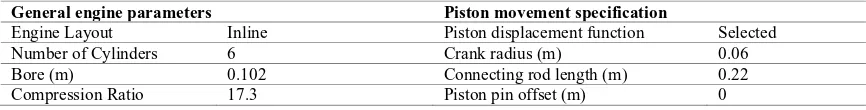
[image:2.544.46.479.562.617.2]The general data section allows the user to input general parameters relevant to the specific engine being analysed. Parameters are separated into two tabs, general engine parameters which contains input fields for engine name, type of engine, number of cylinders, bore, and compression ratio. Piston movement specification is related to the data of piston movement which includes stroke, connecting rod length, etc. All data is taken directly from the Cummins ISBe220 engine being modelled and will not change with the comparison of different fuels. The following data in Table 1 was inserted.
Table 1. General Engine Data
General engine parameters Piston movement specification
Engine Layout Inline Piston displacement function Selected
Number of Cylinders 6 Crank radius (m) 0.06
Bore (m) 0.102 Connecting rod length (m) 0.22
2.2.Experimental Results
The experimental data sets for the Cummins ISBe220 engine are listed in Table 2, which consists of three pure diesel cases and one diesel-Triacetin (biodiesel) blend case.
Table 2. Summary of experimental data
Case Fuel Type RPM Load (%) Power
(Kw)
Torque (Nm)
Boost exit (kPa)
Fuel Flow Rate (LPM)
IP (kW)
1 100% Diesel 1600 50 78.75 470.00 68.67 0.334 75.87
2 100% Diesel 1500 100 127.72 809.55 152.37 0.524 118.23
3 100% Diesel 1500 47 64.53 408.14 49.49 0.285 63.46
4 90% Diesel +10% Triacetin 1500 35 36.24 228.29 17.44 0.195 39.87
2.3.Sketcher and Mesh
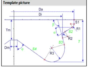
The sketcher section allows the user to define the piston bowl shape, injector shape, modify the block structure, define selections and fix the compression ratio to a set value.
The piston shape is important as the geometry controls the flow of air and fuel in the cylinder. The design and measurements were estimated using a template from ESED and images of the piston shape of the Cummins ISBe220 engine. The cross-sectional area of the piston are seen in Figure 1.
A set of computational meshes are created based on the details entered in the block structure section. A dependent average cell size generally reduces computational time however, due to the finer mesh at time of injection, increases the accuracy of the solution. Due to issues with dependent average cell size, an average cell size of 0.0005m was chosen. The mesh generated can be seen in Figure 2. The mesh resolution was decided based on interaction with AVL personnel on the desired mesh resolution for accuracy.
[image:3.544.47.202.337.459.2] [image:3.544.176.483.337.456.2]
Fig. 1. Cross Sectional area of a piston. Fig. 2. Meshes generated of a piston. spacecpacecpacecp
2.4.Spray and combustion model selection
AVL Fire ESED utilizes mathematical models to accurately simulate the fuel spray, evaporation, combustion and emissions of the diesel engine. All the models are combined together to calculate the output data of the engine. The combustion model was chosen to be the ECFM-3Z as this model is especially generated for diesel combustion process. The Wave Child Break-up model was selected for the spray dispersion model. This model increases computational time however significantly increases accuracy. Two different types of evaporation models depending on the fuel type used. A Dukowicz and Multi-component models where selected for pure diesel and biodiesel-diesel blends respectively. For the calculation of the emissions, an Extended Zeldovich model was used for NOX and Lund Flamelet
model for the soot emissions. These models are individually selected in the ESED interface as they were determined to achieve the accuracy while keeping computational time to a minimal [4,5].
2.5.Injection rate setting
pre/main/post. The pre injections are usually used to reduce combustion-generated noise by reducing the rate of heat release early in the injection event. The main injection event then follows the pre injections, which injects the bulk mass of fuel at a much higher rate than the pre injections. The post injections are after the main injection and are generally used to control soot and NOX emissions. The three types of injections combine to have a significant impact
on combustion and can only be performed with a multiple shot injector [6].
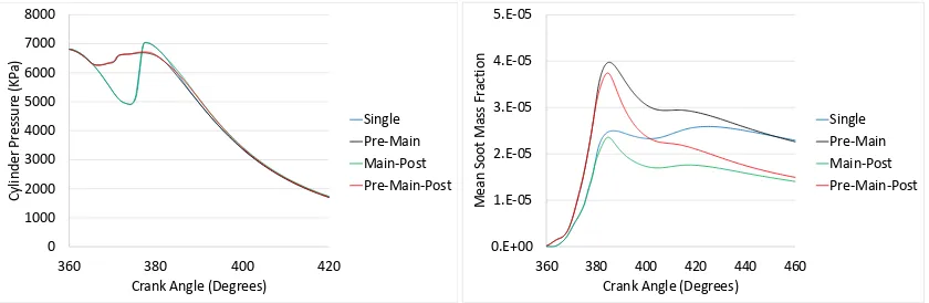
As the injection-rate shape is not known for the Cummins ISBe220 engine, 4 models were developed for pure diesel in Case 3 (1500RPM, 47% load) to investigate the effects of pre- and post- injections. The models consisted of a single main injection, pre-main injection, a main-post injection and a pre-main-post injection-rate shape, which are shown in Figure 3. The fuel mass flow rates in the simulation models were constant as it was found the greater the mass flow rate the greater the combustion due to increased turbulence. To do this the area under the injection curve was the same for all models to ensure consistent mass flow rates. Ensuring the models were under the same conditions with only the injection-rate shaping being changed. The injection-rate shape was the only variable changed in the analysis to ensure the effects of pre and post injections on combustion can be identified.
The cylinder pressure curves of these four injection scenarios are shown in Figure 4(a). It is clear that the addition of both pre and post injections increaseS the area under the pressure curve over a single injection. Therefore increasing the torque and IP of the engine. The majority of the increase in area is due to the pre injection while the post injection has an insignificant effect on the pressure curve. This is due to a greater volume of air in the cylinder (which reduces the effect of combustion) at post injection. A reduction in combustion delay can also be seen by a pre injection. Overall, the pressure curves for both fuel types are clearly affected by the addition of pre and post injections.
Soot and NOx emissions would be reduced by
employing pre and post injection strategies. The soot mass fractions (SMF) for multiple injection strategies are shown in Figure 4(b). It is clear that that a pre injection greatly increases the soot initially. The research states this may occur when used at light loads due to the low temperature and weak airflow. Once a main injection is employed after the pre injection, the soot levels significantly decrease due to the evaporation of the soot. When a post injection is used, the soot reduces dramatically to the lowest recorded level with all models. This is due to a post injection finalizing the combustion process and forcing the soot into the squish area. The models prove that that by utilising a pre injection the soot increases at this point into the combustion process compared to single injections. However by employing a post injection, the soot can be dramatically reduced due to the finalization of combustion.
[image:4.544.50.259.219.353.2]
Fig. 4. Cylinder pressure (a); and soot mass fraction (b) for 1500 RPM 47% load 100% diesel (Case 3). 0 1000 2000 3000 4000 5000 6000 7000 8000
360 380 400 420
Cylinder Pr
essur
e
(KP
a)
Crank Angle (Degrees)
Single Pre-Main Main-Post Pre-Main-Post 0.E+00 1.E-05 2.E-05 3.E-05 4.E-05 5.E-05
360 380 400 420 440 460
Mean Soot Mass Fr
action
Crank Angle (Degrees)
[image:4.544.64.484.489.626.2]Single Pre-Main Main-Post Pre-Main-Post Fig 3. Injection rate shapes for Case 3.
0 0.5 1 1.5 2 2.5
358 362 366 370 374 378 382
Non
-dime
nsionalised Mass Flow
Crank Angle (Degree)
3.Results and Discussions
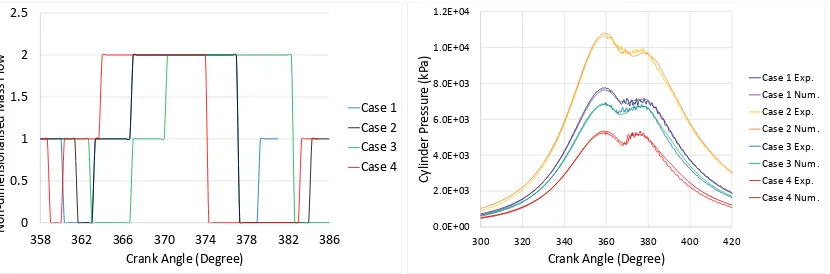
The major aim of this paper is to establish AVL FIRE ESED model on both pure diesel and blends of biodiesel-diesel fuel in a Cummins ISBe220 engine. To determine this, the initial and boundary conditions were taken from the experimental data, and the injection rate information was gather from experiments and then correlated with the cylinder pressure data. The setting of the injection rate shape for all the 4 cases are shown in Figure 5(a). The change of the injection rate is probably due to the setting of the engine management system.
3.1.Cylinder pressure comparison
Figure 5 (b) plots both the experimental and numerically-simulated cylinder pressure profiles for the 4 conditions. It can be seen that the models agree accurately with the experimental data. The errors between the experimental and numerical indicated power (IP) are 1.62%, 2.51%, 2.7%, and 8.85%, for Case 1, 2, 3, and 4, respectively.
For Case 3, the simulated results separate from the experimental curve from a crank angle of approximately 385q. This is due to the impact of the post injection on the pressure curve, and it is a possibility that at this specific load case a post injection was not used. To generate high accuracy pressure curves further investigation into the experimental injection-rate shapes of the Cummins ISBe220 are required. Due to copyright laws, this data could not be retrieved from Cummins, and the data should be retrieved from the experimental engine ECU during experimentation. The pressure curve is established to correlate well with experimental data, with a deviation occurring late into the combustion process.
[image:5.544.64.479.351.488.2]Additionally in Case 4, the simulated results separate from the experimental curve from a crank angle of approximately 383. This is most likely due to the additional air in the cylinder explained by the higher mechanical compression pressure. Another explanation as stated above is due to the impact of the post injection on the pressure curve generating a greater pressure towards the end of combustion. The pressure curve is established to correlate well with experimental data, with a deviation occurring late into the combustion process similar to the previous diesel model.
Fig. 5. Injection Rate shape (a) and cylinder pressure (b) profiles.
3.2.Emission comparison
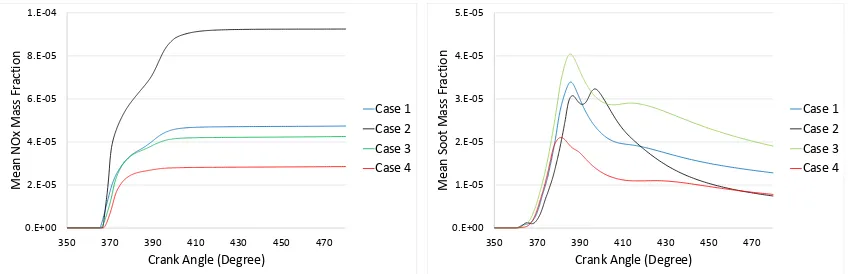
One of the benefits of employing biodiesel fuel is the reduction in NOx and soot emissions. The soot and NOX
emissions of the numerical models are compared with experimental data as shown in Figure 6. It is obvious in the mean NOX figure that the 1500 RPM 100% load 100% diesel condition (case 2) produces the highest amounts of NOX
emissions, followed by 1600 RPM 50% load (case 1), and then 1500 RPM 47% load (case 3). A close correlation occurs between the 1500 RPM 47% load and 1600 RPM 50% load compared to 1500 RPM 100% load suggesting that NOX formation is related to engine load, and therefore the amount of fuel and air combusted. The 1500 RPM 35%
load 10% biodiesel blend (case 4) presents the lowest NOX formation, up to 32.8% less than the 1500 RPM 47%Load
pure diesel load case. This suggests that by utilizing blends of biodiesel in diesel, the NOx formation can be reduced
significantly. However additional models are required to be developed of biodiesel blends to prove the reduction in NOx emissions.
0 0.5 1 1.5 2 2.5
358 362 366 370 374 378 382 386
Non
-dimensionalised Mass Flo
w
Crank Angle (Degree)
Case 1 Case 2 Case 3 Case 4
0.0E+00 2.0E+03 4.0E+03 6.0E+03 8.0E+03 1.0E+04 1.2E+04
300 320 340 360 380 400 420
Cylinder Pr
essur
e
(kP
a)
Crank Angle (Degree)
For the figures of the mean soot mass fractions, it is be seen that the 1500 RPM 47% load diesel case produces the maximum peak soot and final mean soot mass fraction. The 1500 RPM 35% load 10% biodiesel blend produces the minimum peak soot and minimum final soot mass fraction which is 60% less than 1500 RPM 40% load pure diesel model. The results suggest that by utilising blends of biodiesel the soot emissions can be reduced, however additional models are required to be developed to prove findings.
[image:6.544.58.482.129.266.2]
Fig. 6. Mean NOX mass fraction (a) and mean soot mass fraction (b).
4.Conclusions
The compression ignition engine uses petroleum fuel sources which are rapidly depleting due to a high demand by society. The need to obtain a renewable fuel source is imperative. Experimental analysis is extremely costly and therefore numerical analysis is required to reduce cost. Computational fluid dynamics (CFD) are a numerical analysis which can calculate to a similar accuracy of experimental analysis. AVL Fire ESED was found to be an exceptional CFD program which can accurately model single component fuels such as diesel and multicomponent biodiesel-diesel fuels.
AVL Fire ESED model was established to model pure diesel and biodiesel-diesel blends. Experimental data of engine performance and emission at four cases (3 pure diesel cases and 1 diesel-triacetin case) were collected from a 6.7 L Cummins ISBe220 engine. Numerical Investigation found that injection-rate shape is crucial for the accuracy of the modelling. An investigation of pre and post injections was performed with the results corresponding remarkably well with researched data.
A triple injection-rate shape is employed by the Cummins ISBe220 engine to generate combustion. Injection-rate shape setting was correlated for all 4 cases. By employing biodiesel blends in diesel fuel a significant reduction in both NOX and soot emissions were identified. A NOX-soot trade off was discovered in the combustion process which
was concluded to be considerably influenced by the injection-rate shape.
References
[1] Ajav EA, Singh B, Bhttacharya TK. Experimental study of some performance parameters of a constant speed stationary diesel engine using ethanol-diesel blends as fuel. Biomass and Bioenergy 1999;17:357-65.
[2] Agarwal AK. Biofuels (alcohols and biodiesel) applications as fuels for internal combustion engines. Progress in Energy Combustion Sci. 2007;33:233-271.
[3] Harch CA, Rasul MG, Hassan NM, Bhuiya MMK. Modelling of Engine Performance Fuelled with Second Generation Biodiesel. Procedia Engineering 2014;90:459-465.
[4] AVL. AVL Fire combustion module Edition 02/2013. 2013. [5] AVL. AVL Fire spray module Edition 02/2013. 2013.
[6] Hotta Y, Inayoshi M, Nakakita K, Fujiwara K. Achieving Lower Exhaust Emissions and Better Performance in an HSDI Diesel Engine with Multiple Injection. SAE Technical Paper 2005-01-0928.
[7] Park C, Kook S, Bae C. Effects of Multiple Injections in a HSDI Diesel Engine Equipped with Common Rail Injection System. SAE Technical Paper 2004-01-0127.
0.E+00 2.E-05 4.E-05 6.E-05 8.E-05 1.E-04
350 370 390 410 430 450 470
Mean NO
x Mass Fr
action
Crank Angle (Degree)
Case 1 Case 2 Case 3 Case 4
0.E+00 1.E-05 2.E-05 3.E-05 4.E-05 5.E-05
350 370 390 410 430 450 470
Mean Soot Mass Fr
action
Crank Angle (Degree)