Tri-axis Convective Accelerometer with
1
Closed-Loop Heat Source
2
Van Thanh Dau1*, Thien Xuan Dinh,2 Lam Bao Dang3, Canh-Dung Tran4, Tung Thanh Bui,5 and Phan Thanh Hoa6* 3
1Research Group (Environmental Health), Sumitomo Chemical. Ltd, Hyogo, 665-8555, Japan
4
2Graduate School of Science and Engineering, Ritsumeikan University, Kyoto, 525–8577, Japan
5
3School of Mechanical Engineering, Hanoi University of Science and Technology, Viet Nam
6
4School of Mechanical and Electrical Engineering, University of Southern Queensland, Queensland QLD 4350,
7
Australia 8
5University of Engineering and Technology, Vietnam National University, Hanoi, Vietnam
9
6 HaUI Institute of Technology, Hanoi University of Industry, Hanoi, Vietnam
10
*Corresponding authors: [email protected] ; [email protected] 11
12
Abstract
13
In this paper, we report the details and findings of a study on tri-axis convective accelerometer, which is designed
14
with the closed-loop type heat source and thermal sensing hotwire elements. The closed-loop heat source
15
enhances the convective flow to the central part where a hotwire is placed to measure the vertical component of
16
acceleration. The simulation was conducted using numerical analysis, and the device was prototyped by additive
17
manufacturing. The device, functioning as a tilt sensor and an accelerometer, was tested up to acceleration of 20g.
18
The experiments were successfully conducted and the experimental results agreed reasonably with those
19
obtained by numerical analysis. The results demonstrated that the closed-loop heat source could reduce the cross
20
effect between the acceleration components. The scale factor and cross-sensitivity had the values of 0.26 μV/g
21
and 1.2%, respectively. The cross-sensitivity and the effects of heating power were also investigated in this study.
22
Keywords: convective accelerometer, tri-axis, closed-loop heater, hotwire, OpenFOAM.
23
I.
I
NTRODUCTION24
Recently, micromachined accelerometers have undergone rapid development, and are widely used in various
25
applications. Solid-state accelerometers have high performance, but also possess some setbacks. They are more
26
fragile, fabricated by complicated process, and need complex packaging in order to remove the squeeze film effect
27
between the proof mass and the accelerometer structure [1]. In Refs. [2], [3], the authors presented the first
28
accelerometers without the proof mass, working under the principles of thermal convection heat transfer. Micro
29
thermal convective accelerometers utilizing thermal bubble have been studied over the last two decades [4]. The
30
operation of this type of sensor is based on the movement of a hot tiny air bubble generated from a heater. From
31
then on, research has been carried out with focus on improving the sensor performance by optimizing the heat
32
transfer [5–25], signal conditioning [26–28], behavior modelling [29–32], or fabrication process [33–35].
33
Most of the developed thermal accelerometers can measure only two components of the in-plane acceleration.
34
Measuring the out-of-plane acceleration is more challenging because the principle of this kind of sensors is based
35
on natural convective flow, which always aligns with the vertical gravity. Thus, the vertical acceleration requires
36
an out-of-plane structure and has small sensitivity.
37
Leung et al. reported one of the first tri-axis accelerometers. The device is made by polyimide and assisted by
38
wire bonding process for out-of-plane structure [36]. In Ref. [37], the accelerometer is made by micromachining
39
process utilizing polysilicon as the sacrificed layer and polyimide as the structural layer. To launch the device, the
structures firstly need to be locked between each other and anchored to the substrate. This device allows
1
obtaining the Z sensitivity of 25 µV/g.
2
In the works published by Rocha and Silva [38–41], a polymeric three-axis device was fabricated by
3
conventional micromachining and injection molding. The heating and the temperature sensing structures, made
4
of aluminum, were patterned on a flexible polymeric membrane. The membrane was then folded so that parts of
5
the membrane consisting of z-sensors were placed above and under the central part, which consisted of the heater
6
and the in-plane x-y sensors. The device with performance of approximately 2.2 µV/g was packaged using
7
polystyrene parts made by injection molding, and was hermetically sealed.
8
The Z-axis acceleration detected by in-plane structure was reported by Mailly et al. in [42,43] using integrated
9
CMOS (complementary metal–oxide–semiconductor). This device measures out-of-plane acceleration by using
10
common mode of the in-plane structure. MEMSIC Inc. has also claimed a three-axis device. However, the principle
11
is not disclosed, although it is said that the device uses the common mode of the electric bridge [4,44]. Another
12
principle for the triple-axis accelerometer has been proposed in [45] but without further discussion about
13
efficiency. In Refs. [46,47], the design of three-axis thermal accelerometer using segmented circular heater was
14
mentioned. Using numerical simulation, Ogami et al. reported that the sensor could reliably determine a vast
15
range of vertical acceleration, specifically, ±10,000 g [47]. However, the experimental details were omitted.
16
As already mentioned above, it is difficult to detect the acceleration in the z-direction accurately. For measuring
17
this acceleration, the temperature detecting components need to be arranged above and below the heater. When
18
acceleration occurs, the detected temperatures change, but only by small amount. It has been found that the
Z-19
axis detection accelerometer has a close relation with the natural convection of the flow inside a cavity heated
20
from below [48–53]. In recent years, many researchers have found that boundary conditions [48,49] and heater
21
geometry [50,51] have substantial impact on the pattern of these convective flows. Because of the temperature
22
distribution, the local heating of the quiescent air over the heater surface produces density gradient directed
23
toward the decrease in the medium temperature, and convective flow occurs in the form of thermal plume when
24
the buoyancy exceeds the viscous friction [53]. For a single local heater under heating conditions, the hot air rises
25
upwards along the vertical axis going through the heater. Therefore, the convective flow has high stability in the
26
plane of the heater, but is less stable in the vertical direction [54]. These characteristics of flow from the
plate-27
type heater usually employed in convective accelerometer reduce the sensitivity of the vertical acceleration
28
sensing. Another setback is the interference between the measured acceleration components. Because of
29
arrangement of the temperature detectors, when the acceleration in one direction causes a change in the
30
corresponding temperature, it also affects the temperature elements of the remaining directions and distinctly
31
lowers the measurement accuracy.
32
In this paper, we demonstrate a novel approach to develop a tri-axis convective accelerometer with reduced
33
cross effect between the vertical and horizontal acceleration. This design, inspired by the numerical simulation in
34
[55], involves development of accelerometer utilizing the ring-type heat source. The designed device consists of a
35
closed-loop heater with hotwires placed both inside and outside of the heater. The closed-loop heater enhances
36
the convective flow to the central part, where the temperature detector is positioned to measure the vertical
37
component of acceleration. Outside the loop, other hotwires detect the horizontal components. The
38
characteristics of the sensor are experimentally validated by tilting the device and by applying linear acceleration.
39
The principles of the device, numerical simulation, and the effect of several governing parameters are also
40
explored to investigate the reliability of the device.
41
II.
WORKING
PRINCIPLE
42In general, the principle of acceleration sensing can be summarized as follow. The sensing chip, formed by one
43
heater placed at the center and surrounded by hotwires (temperature detector), is packed in an airtight chamber.
44
At the initial state, the heater creates a symmetrical temperature profile inside the chamber. When the device is
45
subjected to acceleration, the locally heated air moves in the direction of this applied acceleration, causing
temperature distortions 𝑇, which are then sensed by the hotwires. For horizontal measurement ax or ay, the
1
output of sensor is given by 𝑇𝑥 or 𝑇𝑦 at the X or Y hotwires, respectively (Fig. 1a). For vertical measurement,
2
the output is determined by the output of 𝑇𝑧 at the Z hotwire.
3
In most of the conventional accelerometers reported in the first section, the heater is suspended at the center
4
and the hotwires are located around the heater. Consequently, the change in temperature caused by the variation
5
of the vertical acceleration is low in comparison with that caused by the variation of the horizontal acceleration,
6
and the cross–sensitivities between these measurements are high. In our design shown in Fig. 1, the heater forms
7
a full loop and the hotwires are located both inside and outside of the heater. The plane of the hotwires has a
8
small elevation from the heater plane for vertical and horizontal measurements.
9
In the closed-loop heater, the primary flow concentrates strongly within the central portion even if heat is not
10
supplied there [56,57]. The high temperature air is concentrated in the central part, except in a very thin layer
11
above the heat source. As this concentrated hot air has high buoyancy, the temperature varies with the vertical
12
acceleration az. This increases the sensitivity of the vertical measurement significantly and reduces the cross-effect
13
of horizontal acceleration, which is one of the limits of the conventional design.
14
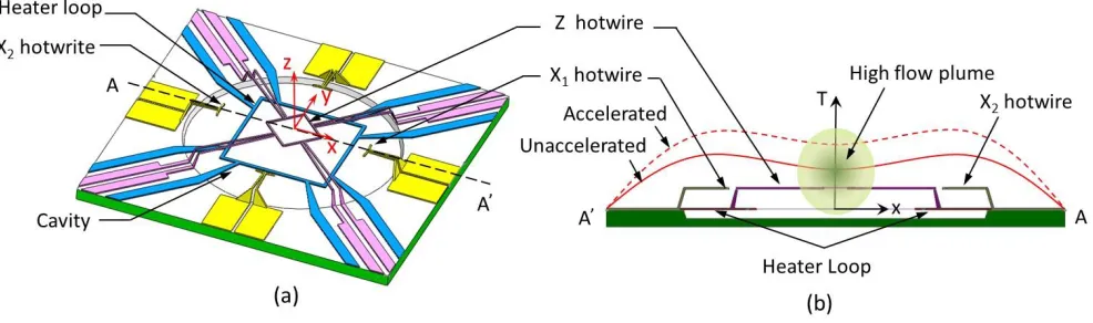
15
[image:3.612.62.555.302.448.2]16
Figure 1. (a) Configuration of the sensor with the radius of the cavity of 0.75 mm. (b) Position of the hotwires in 17
the cross section along the A–A axis and principle to measure the vertical acceleration. The hotwires are on the 18
same plane, and the heater is underneath. The Z hotwire is above the central portion of the heater to utilize 19
convectively heated air from the ring-type heater. 20
III.
SIMULATION
AND
DESIGN
21The thermofluidic phenomena in the sensor are described by the temperature dependence of the fluid density.
22
This process is governed by the laws of conservation of mass, momentum, and energy for compressible fluids and
23
is expressed as follows:
24
𝜕ρ
∂t+ ∇ ∙ (𝜌𝑢⃗ ) = 0 (1)
25
∂ρu⃗⃗
∂t + ∇ ∙ (ρu⃗ 𝑢⃗ ) = −∇𝑝 + ∇ ∙ (𝜇∇𝑢⃗ ) + 𝜌𝑎 (2)
26
∂ρcp𝑇
𝜕𝑡 + 𝑢 ∙ ∇𝜌𝑐𝑝𝑇 = ∇ ∙ (𝜆∇𝑇) (3)
27
where 𝑢⃗ and p are velocity and pressure of the fluid flow, respectively. Similarly, 𝜌, 𝑐𝑝,𝜇and 𝜆 are density,
28
specific heat, viscosity, and thermal conductivity of the fluid, respectively. The term 𝑎 is the acceleration vector,
29
while 𝜌𝑎 represents the momentum source because of the change in fluid density. As air is the medium in this
30
study, the ideal gas law for compressible flows is valid. This can be stated as
𝑝 = 𝜌𝑅𝑇/𝑀𝑤 (4)
1
where R is the universal gas constant and Mw is the molecular weight of the gas.
2
The sensor is decomposed into a hexagonal mesh clustered near the heater and walls to capture the steep change
3
of temperature. The flow parameters on this mesh are then obtained by the computational fluid dynamics package
4
OpenFOAM, which uses the finite volume method to discretize the governing equations. The simulation model is
5
presented in Fig. 2.
6
Figure 2. (a, b) Simulation results and (c) meshing of the model. Simulation shows that (a) flow velocity concentrates within the region above the center of ring-type heater while (b) the temperature is highest at the thin layer around the heat source.
From the simulation, it can be seen that the high temperature air is formed in the central portion above the
7
heater except a thin layer around the heat source and the peak of temperature is distributed toward the center
8
of the rim. For the velocity, the main part of the convection is strongly concentrated in the central part of the
9
heater where no heat is supplied at the bottom. By placing a sensing element in this region, the specific character
10
of the closed-loop type heater allows efficient measurement of the vertical acceleration and reduces the
cross-11
effect of the horizontal acceleration. All of these phenomena will be discussed in the following paragraphs.
12
Considering the earth’s gravity g, we discuss the sensor performance by comparing the initial state 𝑎(0, 0, 1 g)
13
and the accelerated state 𝑎(𝑎𝑥, 𝑎𝑦, 𝑎𝑧− 1 g). Because of the equivalency between the x and y components, only
14
the measurements of x and z components of acceleration are taken into consideration. The sensitivity of the
15
sensor can be determined from 𝑇𝑥 and 𝑇𝑧, which are the temperature changes at the X hotwire and Z hotwire
16
when the accelerations are applied on the X and Z axes, respectively. The cross-effect between the vertical and
17
horizontal measurements is determined by 𝑇𝑥𝑧 on the X hotwire under the effects of az and by 𝑇𝑧𝑥 on Z hotwire
18
under the effects of ax. In the simulation, the sensitivity and cross-effect are examined by simultaneously applying
19
ax and az.
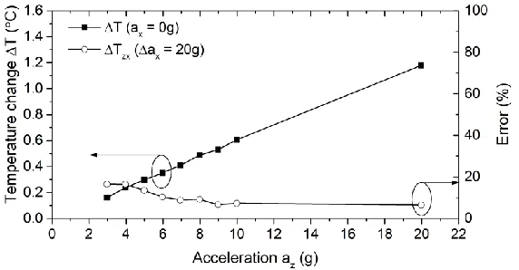
20
Figure 3 shows that the variation in temperature differences on the X hotwire (𝑇𝑥) with 𝑎𝑥, ranging from 0 g
21
– 20 g, for the cases of 𝑎𝑧 = 1 𝑔 and 𝑎𝑧 = 21 𝑔. It is observed that 𝑇𝑥 varies linearly with 𝑎𝑥 with the sensitivity
22
𝑇𝑥⁄𝑎𝑥~ 0.29 °C/g. The effect of 𝑎𝑧 on 𝑇𝑥, error 𝑇𝑥𝑧(%) = (𝑇𝑥,𝑎𝑧=21𝑔−𝑇𝑥,𝑎𝑧=1𝑔)/𝑇𝑥,𝑎𝑧=21𝑔, is within
23
5% (in comparison with 𝑇𝑥 at 𝑎𝑧 = 1𝑔).
24
[image:4.612.165.453.166.342.2]1
Figure 3. Variation of the temperature difference between the hotwires X1 and X2 for 𝑎𝑥 ranging from 1 to 20 g.
2
The error represents the percentage of temperature change 𝑇𝑥𝑧 between 𝑎𝑧= 21 𝑔 and 𝑎𝑧= 1 𝑔.
3
4
5
Figure 4. Variation of the temperature difference between the accelerated state and the normal state at the Z 6
detector, with 𝑎𝑧 ranging from 1 to 20 g. The error represents the percentage of temperature change 𝑇𝑧𝑥
7
between 𝑎𝑥= 20 𝑔 and 𝑎𝑥 = 0 𝑔.
8
Similarly, for cases of 𝑎𝑥= 0 g and 𝑎𝑥 = 20 g, Fig. 4 shows the change of temperature on Z hotwire (𝑇𝑧) with
9
𝑎𝑧. Again, 𝑇𝑧 increases linearly with 𝑎𝑧 up to 𝑎𝑧 = 20 𝑔 with the sensitivity 𝑇𝑧⁄ ~ 0.059 °C/g𝑎𝑧 .
10
With 𝛼 as the temperature coefficient of resistance of the hotwire material, the conversion between the
11
hotwire temperature and its resistance can be expressed as:
12
𝑅 = 𝑅𝑟𝑒𝑓(1 + 𝛼𝑇) (5)
13
where ∆𝑇 = 𝑇 − 𝑇𝑟𝑒𝑓, R, and Rref are the resistances of the hotwire at temperature T and Tref, respectively. In the
14
experiment, the resistance is measured by supplying a constant direct current (d.c) and monitoring its voltage.
15
IV.
P
ROTOTYPE ANDE
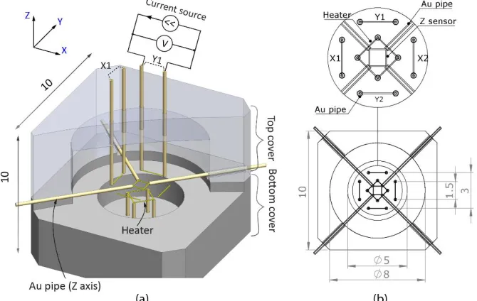
XPERIMENTAL SETUP16
The sensor designed for the experiment consisted of top and bottom parts (Fig. 5a), which were connected as
17
the male-female components of an assembly, to prevent the leakage of the air, which was used as the working
18
medium in this device. The top view showing the layout of the hotwires and the heater is presented in Fig. 5b. The
19
dimensions 10 mm × 10 mm × 8 mm (width × length × thickness) of the fabricated device are chosen based on
20
several designs available for the dual axis convective accelerometer and the consideration of our available facilities
21
[12]. The hotwire and heater were made of tungsten wire with diameter 10 µm. To place these elements at the
22
desired positions, hollow capillary gold (Au) pipes 200 µm × 25 µm (outer diameter × thickness) were used as the
[image:5.612.174.460.267.416.2]lead pins. The capillaries were assembled with the packing and fixed with epoxy glue; the tungsten wires were
1
then inserted through those capillaries and connected with each other. Together they created floating structures.
2
This method allowed the construction of the sensor with high precision and cost-effectiveness.
3
Figure 6a shows the prototype made of polypropylene. The heaters were supported by four Au pipes and were
4
integrated with the bottom part. The hotwires were connected to the top part, where each X and Y hotwire was
5
supported by two Au pipes at its end. The Z sensor and the heater were supported by four Au capillaries to form
6
a loop-like resistor. The positioning of the capillaries was assisted by assembly jig (not shown). After the hotwires
7
were connected and the electrical connections were confirmed, the top and bottom part were assembled and
8
sealed by epoxy at the standard room condition (22–25 °C, 60% RH).
9
The temperature coefficient of resistance was measured as 𝛼 ≈ 4500 ppm/°C using the temperature controlled
10
chamber (Espec SH-222). Without conditioning circuit, the measurement of the hotwire/heater was conducted by
11
four-point probe measuring technique. A constant electric current was applied by the TEXIO DC power source
12
(PW18-1.8AQ) and the output voltage was continuously recorded by a computer via NI (National Instrument Ltd.,)
13
signal express data logging interface connected to the NI-9234 data acquisition device with the sampling rate of
14
25.6 kHz. At the initial state, the measured resistance values of the hotwires X, Y, Z, and heater were 1.7, 1.9, 1.2,
15
and 1.3 Ω, respectively.
16
Figure 5. (a)Schematic view of the designed prototype with the cut-view showing the lead pin (made by Au capillary) and hotwires. (b) Dimensions of the central regions.
The sensing performance of the device was checked by the tilting test and linear acceleration test. For the tilting
17
test, the device was attached to a circular disc placed vertically and tilted around the X and Y axes, while the
18
voltages on the hotwires X, Y and Z were read out (see Fig. 6c).
19
The linear acceleration sensing was tested by placing the device at the edge of a self-developed turntable (see
20
Fig. 6b), whose angular velocity was controlled by a direct current motor with integrated encoder (Tsukasa Electric
21
Ltd.). When the turntable rotated, the centrifugal acceleration acted to the device was 𝑎 = (2πn)2𝑟𝑡, with n and
22
𝑟𝑡 = 4.5 cm were the angular speed and radius of the turntable, respectively. The on-chip circuit was connected
23
via the slip-ring to the off-chip circuit to transfer the signals while the turntable rotated. The table revolution had
24
a maximum value of 700 rpm during the experiment, and its rotation was recorded by the PIC18F4520
25
microcontroller via encoder motor. The output voltage was extracted one minute after the turntable reached the
26
rotation speed to ensure that the centrifugal acceleration and the flow inside device were stable.
[image:6.612.140.475.313.525.2]Figure 6. (a)Close-up view of the prototype showing hotwires and Au pipes, (b) package device with holder placed on the turntable, (c) tilting test: experiment for determining tilting along the X and Y axes, and (d) linear acceleration test: experiment for determining centrifugal acceleration along the X and Z axes.
The start-up time of the device was acquired from the transient time of the output voltage on the hotwire X
1
(plotted in Fig. 7). It was found that the start-up time was around 100 ms for the X axis, which was located 1.0 mm
2
from the heater, with the applied current of heater 𝐼ℎ𝑒𝑎𝑡𝑒𝑟= 110𝑚𝐴 ( 𝑉ℎ𝑒𝑎𝑡𝑒𝑟 = 0.177 𝑉). This start-up time,
3
including the time delay in the electric circuit, also represented the time scale for heat transfer from the heater
4
to the hotwire until the temperature in the sensor chamber became stable.
5 6
Figure 7. Experimental result for the transient measurements of voltages on the heater and the hotwire X.
V.
E
XPERIMENTAL RESULT7
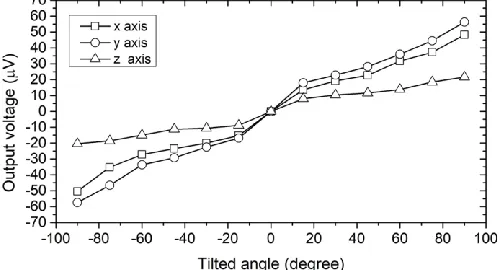
1. Tilting sensitivity of X and Y axes 8
For the tilting test, the outputs of hotwires were monitored while the sensor was being rotated to ensure that
9
the corresponding hotwire moved from underneath the heater to the top of the heater. In Fig. 8, they are the
10
tilted angles -90° and +90°. The output voltage on X and Y hotwires are recorded when the sensor is tilted around
the Y axis and the X axis, respectively. The output on the Z axis is recorded when the sensor is tilted around the X
1
axis (see Fig. 6c).
2
Figure 8. Output voltages on the X, Y, and Z hotwires while tilting around the X and Y axes.
The heater is heated with a constant current of 110 mA. The change in the heater resistance allows us to
3
estimate the temperature of the heater by using the relation 𝛼Δ𝑇 = Δ𝑅/𝑅, and its value is found to be
4
approximately 70 °C. From Fig. 8, the sensitivities on the X axis and the Y axis are averaged as 𝑉𝑥𝑥 = 0.62 µV/o and 5
𝑉𝑦𝑦 = 0.53 µV/o. The input of the Z hotwire while rotating around the X axis is 𝑉𝑧𝑧= 0.23 µV/o, which is of the
6
same order as those of the X and Y axes. With the measured resistance at initial state of 𝑅x/𝑅𝑧= 1.7 (see part IV),
7
the change in temperature in the hotwires X and Z is approximated as Δ𝑇𝑥/Δ𝑇𝑧 = (Vxx/𝑉𝑧𝑧)/(𝑅𝑥/𝑅𝑧). For the
8
result in Fig. 8, the temperature Δ𝑇𝑥 is 1.9 times higher than Δ𝑇𝑧. This value relatively agrees with the simulation
9
results presented in Figs. 2 and 3.
10
11
[image:8.612.183.433.97.232.2]2. Effect of supply current on the heater 12
[image:8.612.314.549.411.543.2]Figure 9. Effect of the heating current to the output voltage for the X axis sensing
Figure 10. Effect of heating current to the output voltage for the Z axis sensing
The sensing ability of devices can be enhanced by increasing the temperature of the heater, since the
13
temperature of the heater is directly related to how the medium can move inside the device [12,43]. A low
14
temperature heater will significantly restrain the flow and degrade the sensor performance. The experiment was
15
repeated in this study where the heater was subjected to three currents Ih = 80 mA, 110 mA, and 130 mA. The
16
obtained results are shown in Figs. 9 and 10. It can be seen that when the current increases from 80 mA to 130
17
mA, the output increases by 127% of the magnitude for the X axis and by 146% for the Z axis. Therefore, the output
18
voltages at the hotwires can be adjusted by the heater current, which can be used to accelerate the experiment.
19
3. Sensing linear acceleration 20
For the linear acceleration test, the output voltage is monitored while the sensor is placed at the edge of the
21
turntable rotating at 135 rpm (centrifugal acceleration 0.89 g) and the heater is heated with a current Ih = 110 mA.
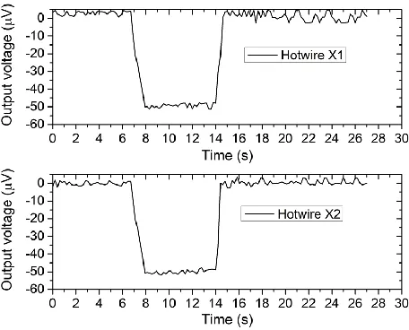
Figures 11 and 12 show the transient output voltage of the hotwires X1 and X2 when the acceleration is along the X 1
and Z axes, respectively (see experimental setup in Fig. 6d). The changes between these two hotwires are almost
2
similar in time, with a mismatch of only 210 ms at the left-peak slope. In Fig. 11, the two hotwires change their
3
voltages opposite to each other, whereas in Fig. 12, their voltages change similarly, indicating that the heated air
4
region changes the temperature of the X hotwire asymmetrically and symmetrically under the x and z applied
5
accelerations, respectively.
6
The average noises are approximately 5 µV, significantly larger than the resolution of the 24-bit measuring
7
device NI-9234 data acquisition. Therefore, the resolution of the sensor can be calculated as the signal-to-noise
8
ratio, as shown in Figs. 11 and 12, and it is equivalent to 0.09g. The results also show very small drift evolution,
9
nevertheless, the long-term drift evolution was not thoroughly tested for our device.
10
As the magnitudes of the voltages are almost the same in each case (Figs. 11 and 12), the effect of the Z
11
acceleration can be cancelled out easily by means of a conventional electric circuit such as by forming half
12
Wheatstone bridge by the pair of X hotwires. This kind of circuit is common in use in various sensing techniques, as
13
reported in numerous literature [37],[39].
14
15
[image:9.612.319.547.275.459.2]Figure 11. Transient response of the hotwires X with acceleration applied along the X axis.
Figure 12. Transient response of the hotwires X with acceleration applied along the Z axis
16
Figure 13 shows the variation of the output voltage on the hotwires X with respect to the centrifugal
17
acceleration applied to the X axis by the turntable (see Fig. 6d). The two X hotwires change their resistance
18
opposingly when the scale factors of the hotwires X1 and X2 are SFxx1 = -27.8 µV/g and SFxx2 = +26.7 µV/g, with the 19
non-linearities (the ratio of output variation to maximum output full scale) of these output voltages being 2.7%
20
and 2.2%, respectively.
21
The results depict that the output voltage changes linearly with the change of the rotation speed until the
22
centrifugal acceleration reaches 21g. Meanwhile, the output voltage of the Z hotwire is significantly lower with
23
the scale factor of SFzx = 2.2 µV/g. These results indicate that the cross-sensitivity between the two axes is less 24
than 8%, thereby closely matching with the simulation.
[image:9.612.64.306.275.458.2]Figure 13. Output of the X axis and Z axis when the centrifugal acceleration is applied along the X axis by the turntable (rotating speed from 25 rpm to 700 rpm).
1
Similarly, Fig. 14 shows the output voltages of the hotwires in the X and Z axes while the centrifugal
2
acceleration is applied to the Z axis (see the experimental setup in Fig. 6d). The two X hotwires are parallel with the
3
plane of the turntable and should have similar response to the acceleration. This is confirmed by the data below
4
where the two hotwires respond similarly. The scale factors of the X hotwire under Z acceleration are SFxz1 = 37.7 5
µV/g and SFxz2 = 37.5 µV/g. If the X hotwires are conventionally connected by the half-bridge circuit, the total output 6
of the X axis will be cancelled out (Fig. 14). In the meantime, the scale factor and the nonlinearity of Z hotwire under
7
the Z acceleration are SFzz = 10.2 µV/g and 3.8%, respectively. 8
[image:10.612.175.445.64.210.2]9
Figure 14. Output of the Z axis and the X axis when the centrifugal acceleration is applied along the Z axis by the turntable (rotating speed is from 25 rpm to 700 rpm and the current at the heater is Ih= 110 mA)
Overall, the sensing performance of the present device is in the same order as the values in recent
10
publications. In the simulation, the relative sensitivity of 𝑇𝑧/ 𝑇𝑥 is in the same order with simulated result
11
reported by other research group [58]. However, the sensing performance of the vertical acceleration of the
12
presented device is less significantly affected by the horizontal acceleration. The performance of several published
13
tri-axis convective accelerometers is summarized in Tab. 1. With these performing characteristic, the presented
14
device and those sensors are in the same grade as classified in [59].
15
Table 1. Characteristics of some published tri-axis convective accelerometer
16
X Y Z Vzx (effect of ax on the Z axis)
Bahari and Leung [36,37] 66 µV/g 64 µV/g 25 µV/g 84%
Rocha and Silva et al [38,39] 8.4 µV/g 7.9 µV/g 2.2 µV/g Not reported Mailly and Nguyen et al [42,43] 7.2 mV/g 10 mV/g 0.4 mV/g Not reported
This work 27.8 µV/g (X) 10.2 µV/g 8%
[image:10.612.170.452.367.515.2] [image:10.612.74.537.651.723.2]It is worth noting that using the turntable to generate linear acceleration also induces Coriolis acceleration
1
to the moving convective flow inside the device. The contribution of the Coriolis acceleration, however, is
2
insignificant because the gravity driven flow has limited velocity in tiny confined space. The Coriolis acceleration
3
is calculated as 2ω⃗⃗ × U⃗⃗ [60–64], where U is the velocity of flow inside the device and is estimated by simulation
4
in order of millimeters per second (please refer to Fig. 2). The ratio of the centrifugal acceleration to the Coriolis
5
acceleration, ω𝑟𝑡/2𝑈, is therefore three orders of magnitude. Another concern in our experimental work is the
6
output of tilting performance, which was not as linear as predicted by the simulation. The reasons are probably
7
(i) the imperfection of the assembly process and (ii) the shape of the heater. While the circular-loop is ideal for
8
the symmetry of device, it was not implemented for experimental measurement. We have confirmed by the
9
simulation that the effect of the closed-loop heat source is more pronounced in the circular shape, however, the
10
square shape heater in this work allows us to construct the sensor with cost-effective fabricating resource. These
11
limitations can be improved by using micro fabrication process. As the sensor working principle relies on the heat
12
transfer from the heater to the temperature sensing elements, optimizing the surrounding cavities and sensing
13
element positions may further increase the sensitivity in all directions [45]. Finally, the sensor performance can
14
be boosted by utilizing sensing element which has high resistance and temperature coefficient of resistance
15
[14,17,60,61,65], or packing conditions such as pressure or high thermal conductivity gas [19,66–68].
16
VI.
C
ONCLUSION17
We reported a tri-axis convective accelerometer of millimeter-scale that utilizes a closed-loop heater to
18
improve the sensing performance. The closed-loop heater concentrated the convectively heated air at the central
19
part even though there was no heat source underneath, which helped to reduce the cross-effect of the horizontal
20
acceleration to the vertical acceleration sensing. A numerical simulation was performed and the result was
21
supported by the experimental work. The tilting test showed small cross-effect. The sensor was also tested by
22
applying centrifugal acceleration and the linear relation between the output and the acceleration was achieved
23
up to 20 g. The sensor was fabricated by additive manufacturing and the assembly process was simple, thus
24
allowing quick and cost-effective prototyping to integrate this device into laboratory-scale projects. In addition,
25
the device is made of laminated parts and can be potentially compatible with the conventional microfabrication
26
process for significant reduction in the cost.
27 28
ACKNOWLEDGEMENT
29
This research is funded by the Vietnam National Foundation for Science and Technology Development
30
(NAFOSTED) under grant number 107.01-2015.22
31
References
32
[1] A. Albarbar, S.H. Teay, MEMS Accelerometers: Testing and Practical Approach for Smart Sensing and Machinery Diagnostics, in:
33
Adv. Mechatronics MEMS Devices II. Microsystems Nanosyst., Springer, Cham, 2017: pp. 19–40.
doi:10.1007/978-3-319-32180-34
6_2.
35
[2] R. Dao, D.E. Morgan, H.H. Kries, David M. Bachelder, Ricardo Dao, Denny E. Morgan, Harold H. Kries, David M. Bachelder,
36
Convective accelerometer and inclinometer, US5581034, 1996.
37
[3] A.M. Leung, J. Jones, E. Czyzewska, J. Chen, B. Woods, Micromachined accelerometer based on convection heat transfer, in: Proc.
38
MEMS 98. IEEE. Elev. Annu. Int. Work. Micro Electro Mech. Syst. An Investig. Micro Struct. Sensors, Actuators, Mach. Syst. (Cat.
39
No.98CH36176), IEEE, 1998: pp. 627–630. doi:10.1109/MEMSYS.1998.659830.
40
[4] S. Liu, R. Zhu, Micromachined Fluid Inertial Sensors, Sensors. 17 (2017) 367. doi:10.3390/s17020367.
41
[5] V. Milanovic, E. Bowen, M.E. Zaghloul, N.H. Tea, J.S. Suehle, B. Payne, M. Gaitan, Micromachined convective accelerometers in
42
standard integrated circuits technology, Appl. Phys. Lett. 76 (2000) 508. doi:10.1063/1.125803.
43
[6] S. Billat, H. Glosch, M. Kunze, F. Hedrich, J. Frech, J. Auber, H. Sandmaier, W. Wimmer, W. Lang, Micromachined inclinometer with
44
high sensitivity and very good stability, Sensors Actuators, A Phys. 97–98 (2002) 125–130. doi:10.1016/S0924-4247(01)00824-X.
45
[7] F. Mailly, A. Martinez, A. Giani, F. Pascal-Delannoy, A. Boyer, Design of a micromachined thermal accelerometer: Thermal
46
simulation and experimental results, Microelectronics J. 34 (2003) 275–280. doi:10.1016/S0026-2692(02)00194-5.
47
[8] F. Mailly, A. Giani, A. Martinez, R. Bonnot, P. Temple-Boyer, A. Boyer, Micromachined thermal accelerometer, Sensors Actuators
A Phys. 103 (2003) 359–363. doi:10.1016/S0924-4247(02)00428-4.
1
[9] X.B. Luo, Z.X. Li, Z.Y. Guo, Y.J. Yang, Study on linearity of a micromachined convective accelerometer, Microelectron. Eng. 65 (2002)
2
87–101. doi:10.1016/S0167-9317(02)00731-1.
3
[10] R. Zhu, H.G. Ding, Y. Su, Z.Y. Zhou, Micromachined gas inertial sensor based on convection heat transfer, Sensors and Actuators
a-4
Physical. 130 (2006) 68–74. doi:10.1016/j.sna.2005.11.022.
5
[11] D.S. Lee, Thermal accelerometer based predictive drop sensor, Sensors Actuators, A Phys. 135 (2007) 889–894.
6
doi:10.1016/j.sna.2006.09.023.
7
[12] V.T. Dau, D. Viet Dao, S. Sugiyama, A 2-DOF convective micro accelerometer with a low thermal stress sensing element, Smart
8
Mater. Struct. 16 (2007) 2308–2314. doi:10.1088/0964-1726/16/6/034.
9
[13] V.T. Dau, D.V. Dao, M. Hayashida, T.X. Dinh, S. Sugiyama, A Dual Axis Accelerometer Utilizing Low Doped Silicon Thermistor, IEEJ
10
Trans. Sensors Micromachines. 126 (2006) 190–194. doi:10.1541/ieejsmas.126.190.
11
[14] V.T. Dau, D.V. Dao, T. Shiozawa, S. Sugiyama, Convective Gas Gyroscope Based on Thermo-Resistive Effect in Si P-N Junction, in:
12
TRANSDUCERS 2007 - 2007 Int. Solid-State Sensors, Actuators Microsystems Conf., IEEE, 2007: pp. 2525–2528.
13
doi:10.1109/SENSOR.2007.4300685.
14
[15] V.T. Dau, T. Otake, T.X. Dinh, D.V. Dao, S. Sugiyama, A multi axis fluidic inertial sensor, in: Proc. IEEE Sensors, IEEE, 2008: pp. 666–
15
669. doi:10.1109/ICSENS.2008.4716529.
16
[16] V.T. Dau, T. Otake, T.X. Dinh, S. Sugiyama, Design and fabrication of convective inertial sensor consisting of 3DOF gyroscope and
17
2DOF accelerometer, in: TRANSDUCERS 2009 - 2009 Int. Solid-State Sensors, Actuators Microsystems Conf., IEEE, 2009: pp. 1170–
18
1173. doi:10.1109/SENSOR.2009.5285911.
19
[17] M. Han, J.-K. Kim, G.-M. Bae, Y. Bang, G.S. Lee, S.-W. Kang, D. Jung, Sensitivity improvement of a thermal convection-based tilt
20
sensor using carbon nanotube, Jpn. J. Appl. Phys. 56 (2017) 06GF05. doi:10.7567/JJAP.56.06GF05.
21
[18] M. Han, J.K. Kim, J.H. Park, W. Kim, S.W. Kang, S.H. Kong, D. Jung, Sensitivity and frequency-response improvement of a thermal
22
convection-based accelerometer, Sensors (Switzerland). 17 (2017). doi:10.3390/s17081765.
23
[19] F. Mailly, A. Martinez, A. Giani, F. Pascal-Delannoy, A. Boyer, Effect of gas pressure on the sensitivity of a micromachined thermal
24
accelerometer, Sensors Actuators, A Phys. 109 (2003) 88–94. doi:10.1016/j.sna.2003.09.025.
25
[20] A. Garraud, P. Combette, J. Courteaud, A. Giani, Effect of the Detector Width and Gas Pressure on the Frequency Response of a
26
Micromachined Thermal Accelerometer, Micromachines. 2 (2011) 167–178. doi:10.3390/mi2020167.
27
[21] L. Lin, J. Jones, A liquid-filled buoyancy-driven convective micromachined accelerometer, J. Microelectromechanical Syst. 14 (2005)
28
1061–1069. doi:10.1109/JMEMS.2005.856651.
29
[22] G. Kaltsas, D. Goustouridis, A.G. Nassiopoulou, A thermal convective accelerometer system based on a silicon sensor — Study and
30
packaging, Sensors And Actuators. 132 (2006) 147–153. doi:10.1016/j.sna.2006.04.026.
31
[23] X.B. Luo, Z.X. Li, Z.Y. Guo, Y.J. Yang, Thermal optimization on micromachined convective accelerometer, Heat Mass Transf. 38
32
(2002) 705–712. doi:10.1007/s002310100266.
33
[24] K.-M. Liao, R. Chen, B.C.S. Chou, A novel thermal-bubble-based micromachined accelerometer, Sensors Actuators A Phys. 130–
34
131 (2006) 282–289. doi:10.1016/j.sna.2006.02.049.
35
[25] J. Bahari, J.D. Jones, A.M. Leung, Sensitivity improvement of micromachined convective accelerometers, J. Microelectromechanical
36
Syst. 21 (2012) 646–655. doi:10.1109/JMEMS.2012.2189366.
37
[26] O. Leman, F. Mailly, L. Latorre, P. Nouet, Noise analysis of a first-order thermal ΣΔ architecture for convective accelerometers,
38
Analog Integr. Circuits Signal Process. 63 (2010) 415–423. doi:10.1007/s10470-009-9419-2.
39
[27] A. Garraud, P. Loisel, A. Giani, P. Combette, A. Deblonde, Closed-loop micromachined accelerometer based on thermal convection,
40
Micro Nano Lett. 7 (2012) 1092–1093. doi:10.1049/mnl.2012.0702.
41
[28] J. Lin, C. Lin, C. Lin, A Novel Reliable and Low-Cost Wireless Thermal Convection-Type Angular Accelerometer Made Directly on a
42
Flexible Substrate, Sensors Mater. 27 (2015) 743–754. doi:10.18494/SAM.2015.1111.
43
[29] B. Mezghani, F. Tounsi, M. Masmoudi, Convection behavior analysis of CMOS MEMS thermal accelerometers using FEM and
44
Hardee’s model, Analog Integr. Circuits Signal Process. 78 (2014) 301–311. doi:10.1007/s10470-013-0208-6.
45
[30] B. Mezghani, F. Tounsi, M. Masmoudi, Development of an accurate heat conduction model for micromachined convective
46
accelerometers, Microsyst. Technol. 21 (2015) 345–353. doi:10.1007/s00542-014-2079-x.
47
[31] O. Leman, F. Mailly, L. Latorre, P. Nouet, HDL modeling of convective accelerometers for system design and optimization, Sensors
48
Actuators A Phys. 142 (2008) 178–184. doi:10.1016/j.sna.2007.07.034.
49
[32] A.A. Rekik, F. Azaïs, N. Dumas, F. Mailly, P. Nouet, A Behavioral Model of MEMS Convective Accelerometers for the Evaluation of
50
Design and Calibration Strategies at System Level, J. Electron. Test. 27 (2011) 411–423. doi:10.1007/s10836-011-5207-x.
51
[33] Memsic accelerometer, (n.d.). http://www.memsic.com/accelerometers/ (accessed May 6, 2017).
52
[34] A. Chaehoi, F. Mailly, L. Latorre, P. Nouet, Experimental and finite-element study of convective accelerometer on CMOS, Sensors
53
Actuators, A Phys. 132 (2006) 78–84. doi:10.1016/j.sna.2006.04.057.
54
[35] A.A. Rekik, F. Azais, F. Mailly, P. Nouet, Design-for-manufacturability of MEMS convective accelerometers through adaptive
55
electrical calibration strategy, in: 2012 13th Lat. Am. Test Work., IEEE, 2012: pp. 1–6. doi:10.1109/LATW.2012.6261237.
56
[36] See-Ho Tsang, Abdul Haseeb Ma, K.S. Karim, A. Parameswaran, A.M. Leung, Monolithically fabricated polymermems 3-axis thermal
57
accelerometers designed for automated wirebonder assembly, in: 2008 IEEE 21st Int. Conf. Micro Electro Mech. Syst., IEEE, 2008:
58
pp. 880–883. doi:10.1109/MEMSYS.2008.4443797.
59
[37] J. Bahari, A.M. Leung, Micromachined three-axis thermal accelerometer with a single composite heater, J. Micromechanics
60
Microengineering. 21 (2011) 75025. doi:10.1088/0960-1317/21/7/075025.
[38] L.A. Rocha, C.S. Silva, M.F. Cerqueira, J.F. Ribeiro, L.M. Goncalves, A.J. Pontes, J.C. Viana, A microinjected 3-axis thermal
1
accelerometer, Procedia Eng. 25 (2011) 607–610. doi:10.1016/j.proeng.2011.12.151.
2
[39] C. Silva, J. Noh, H. Fonseca, A. Pontes, J. Gaspar, L.A. Rocha, Fabrication and characterization of polymeric three-axis thermal
3
accelerometers, J. Micromechanics Microengineering. 25 (2015) 85005. doi:10.1088/0960-1317/25/8/085005.
4
[40] L.A. Rocha, C.S. Silva, A.J. Pontes, J.C. Viana, Design of a 3-axis thermal accelerometer using an electro-thermo-fluidic model, in:
5
2012 13th Int. Therm. Mech. Multi-Physics Simul. Exp. Microelectron. Microsystems, IEEE, 2012: p. 1/4-4/4.
6
doi:10.1109/ESimE.2012.6191775.
7
[41] C.S. Silva, R.A. Dias, J.C. Viana, A.J. Pontes, L.A. Rocha, Static and dynamic modeling of a 3-axis thermal accelerometer, Procedia
8
Eng. 47 (2012) 973–976. doi:10.1016/j.proeng.2012.09.309.
9
[42] F. Mailly, H.B. Nguyen, L. Latorre, P. Nouet, CMOS implementation of a 3-axis thermal convective accelerometer, in: IEEE SENSORS
10
2014 Proc., IEEE, 2014: pp. 1471–1474. doi:10.1109/ICSENS.2014.6985292.
11
[43] H.B. Nguyen, F. Mailly, L. Latorre, P. Nouet, A new monolithic 3-axis thermal convective accelerometer: principle, design,
12
fabrication and characterization, Microsyst. Technol. (2014) 1–11. doi:10.1007/s00542-014-2254-0.
13
[44] MXR9159, MEMSIC, (2007).
http://www.memsic.com/userfiles/files/Datasheets/Accelerometer-14
Datasheets/MXR9150GM__Rev_D.pdf (accessed December 11, 2017).
15
[45] Y. Hua, L. Jiang, Y. Cai, A. Leung, Y. Zhao, Single chip tri-axis accelerometer, US7424826, 2008.
16
[46] Y. Ogami, T.X. Dinh, Convective Accelerometer (熱感知型加速度センサ), Japanese patent application JP 2013-96936A, 2013.
17
[47] Y. Ogami, N. Murakita, K. Fukudome, Computational Experiments on the Step and Frequency Responses of a Three-Axis Thermal
18
Accelerometer, Sensors. 17 (2017) 2618. doi:10.3390/s17112618.
19
[48] M. Corcione, Effects of the thermal boundary conditions at the sidewalls upon natural convection in rectangular enclosures heated
20
from below and cooled from above, Int. J. Therm. Sci. 42 (2003) 199–208. doi:10.1016/S1290-0729(02)00019-4.
21
[49] A. Kondrashov, E. Burkova, Stationary convective regimes in a thin vertical layer under the local heating from below, Int. J. Heat
22
Mass Transf. 118 (2018) 58–65. doi:10.1016/j.ijheatmasstransfer.2017.10.096.
23
[50] A. Kondrashov, I. Sboev, P. Dunaev, Heater shape effects on thermal plume formation, Int. J. Therm. Sci. 122 (2017) 85–91.
24
doi:10.1016/j.ijthermalsci.2017.08.012.
25
[51] R.H. Hernández, Natural convection in thermal plumes emerging from a single heat source, Int. J. Therm. Sci. 98 (2015) 81–89.
26
doi:10.1016/j.ijthermalsci.2015.06.010.
27
[52] I.E. Sarris, I. Lekakis, N.S. Vlachos, Natural convection in rectangular tanks heated locally from below, Int. J. Heat Mass Transf. 47
28
(2004) 3549–3563. doi:10.1016/j.ijheatmasstransfer.2003.12.022.
29
[53] A. Kondrashov, I. Sboev, K. Rybkin, Effect of boundary conditions on thermal plume growth, Heat Mass Transf. Und
30
Stoffuebertragung. 52 (2016) 1359–1368. doi:10.1007/s00231-015-1660-x.
31
[54] A. Kondrashov, I. Sboev, P. Dunaev, Evolution of convective plumes adjacent to localized heat sources of various shapes, Int. J.
32
Heat Mass Transf. 103 (2016) 298–304. doi:10.1016/j.ijheatmasstransfer.2016.07.065.
33
[55] D.X. Thien, O. Yoshifumi, Design and analysis of a triple-axis thermal accelerometer, in: 2013 Seventh Int. Conf. Sens. Technol.,
34
IEEE, 2013: pp. 295–300. doi:10.1109/ICSensT.2013.6727662.
35
[56] S. SOMA, Study on the fire-tornado at the former site of the Hifukusho, J. Geogr. (Chigaku Zasshi), Japanese. 84 (1975) 204–217.
36
doi:10.5026/jgeography.84.4_204.
37
[57] K. Kuwahara, Y. Oshima, Thermal Convection Caused by Ring-Type Heat Source, J. Phys. Soc. Japan. 51 (1982) 3711–3719.
38
doi:10.1143/JPSJ.51.3711.
39
[58] C.S. Silva, R.A. Dias, J.C. Viana, A.J. Pontes, L.A. Rocha, Static and dynamic modeling of a 3-axis thermal accelerometer, Procedia
40
Eng. 47 (2012) 973–976. doi:10.1016/j.proeng.2012.09.309.
41
[59] N. Yazdi, F. Ayazi, K. Najafi, Micromachined inertial sensors, Proc. IEEE. 86 (1998) 1640–1659. doi:10.1109/5.704269.
42
[60] V.T. Dau, D.V. Dao, T. Shiozawa, H. Kumagai, S. Sugiyama, Development of a dual-axis thermal convective gas gyroscope, J.
43
Micromechanics Microengineering. 16 (2006) 1301–1306. doi:10.1088/0960-1317/16/7/026.
44
[61] V.T. Dau, D.V. Dao, T. Shiozawa, H. Kumagai, S. Sugiyama, A Single-Axis Thermal Convective Gas Gyroscope, Sensors Mater. 17
45
(2005) 453–463. http://www.scopus.com/inward/record.url?eid=2-s2.0-33645522249&partnerID=MN8TOARS.
46
[62] V.T. Dau, T.X. Dinh, D.V. Dao, S. Sugiyama, Design and Simulation of a Novel 3-DOF MEMS Convective Gyroscope, IEEJ Trans.
47
Sensors Micromachines. 128 (2008) 219–224. doi:10.1541/ieejsmas.128.219.
48
[63] V.T. Dau, T.X. Dinh, C.D. Tran, P.N. Bui, D.D. Vien, H.T. Phan, Fluidic mechanism for dual-axis gyroscope, Mech. Syst. Signal Process.
49
108 (2018) 73–87. doi:10.1016/j.ymssp.2018.02.017.
50
[64] P.T. Hoa, T.X. Dinh, V.T. Dau, Design Study of Multidirectional Jet Flow for a Triple-Axis Fluidic Gyroscope, IEEE Sens. J. 15 (2015)
51
4103–4113. doi:10.1109/JSEN.2015.2411631.
52
[65] V.T. Dau, C.D. Tran, T.T. Bui, V.D.X. Nguyen, T.X. Dinh, Piezo-resistive and thermo-resistance effects of highly-aligned CNT based
53
macrostructures, RSC Adv. 6 (2016) 106090–106095. doi:10.1039/C6RA22872K.
54
[66] R. Mukherjee, P. Mandal, P.K. Guha, Sensitivity improvement of a dual axis thermal accelerometer with modified cavity structure,
55
Microsyst. Technol. 23 (2017) 5357–5363. doi:10.1007/s00542-017-3338-4.
56
[67] R. Mukherjee, J. Basu, P. Mandal, P.K. Guha, A review of micromachined thermal accelerometers, J. Micromechanics
57
Microengineering. 27 (2017) 123002. doi:10.1088/1361-6439/aa964d.
58
[68] P.F. Hodnett, Natural convection between horizontal heated concentric circular cylinders, Zeitschrift Für Angew. Math. Und Phys.
59
ZAMP. 24 (1973) 507–516. doi:10.1007/BF01588154.