PIC TAPE MEASURE
CHE WAN NURUL HIDAYAH BINTI CHE WAN ZAKARIA
A project report submitted in partial fulfillment of the requirements for the Bachelor the Electronic Engineering (Computer Electronic) With Honours
Faculty of Electronic Engineering & Computer Engineering Universiti Teknikal Malaysia Melaka
UNIVERSTI TEKNIKAL MALAYSIA MELAKA
FAKULn KEJURUI'ERAAN ELEK'I'RONIK DAN KEJURUI'ERAAN KOMPUTER W
BORANG PENGESAHAN STATUS LAPORAN
PROJEK SARJANA MUDA I1
Tajuk Projek : PIC TAPE MEASURE
Sesi
Pengajian : 2004-2008
Saya CHE WAN NURUL HIDAYAH BINTI CHE WAN ZAKARIA
mengaku membenarkan Laporan Projek Sarjana Muda ini disimpan di Perpustakaan dengan syarat- syarat kegunaan seperti berikut:
1. Laporan adalah hakmilik Universiti Teknikal Malaysia Melaka.
2. Perpustakaan dibenarkan membuat salinan untuk tujuan pengajian sahaja.
3. Perpustakaan dibenarkan membuat salinan laporan ini sebagai bahan pertukaran antara institusi
pengajian tinggi.
4. Sila tandakan (
4
) :(Mengandungi maklumat yang berdarjah keselamatan atau SUIAT* kepentingan Malaysia seperti yang termaktub di dalam AKTA
RAHSIA RASMI 1972)
TERHAD* (Mengandungi maklumat terhad yang telah ditentukan oleh organisasifbadan di mana penyelidikan dijalankan)
I
(TANLIATANGAN PENULIS)
Alamat Tetap: 1 12 RUMAH MURAII GONG PASIR, 23000 DUNGUN.
TERENGGANU '
9
I
.-/
%.$FTarikh: . . . . .
Lecturer
Faculty Eloctrrnics and Cernruter Engineering (FKEKK) Universiti Teknikal Malaysia Melaka (UTeMl.
> - , 8 Locked E o j 12#C.
Ayer Keroh, 75450 Melaka
DECLARATION
"I declare that this report entitled "PIC Tape Measure" was written by my own except as cited in the references."
"I hereby declare that I have read this report and in my opinion the report is sufficient in terms of scope and quality for granted in Bachelor Degree of Electronic Engineering
(Electronics Computer)."
Signature
Supervisor's Name Date
To
My parents
Cw Zakaria & Halipah
My siblings,
Hasmaria, Halmi, Hasmariza,, Hazwani and Hanapi
For your infinite and unfading love, sacrzjke, patience, encouragement and
ACKNOWLEDGEMENT
All praises and thanks be to Allah (S.W.T), who has guided us to this, never
could we have found guidance, were it not that Allah had guided us.
Words cannot express my gratitude towards my supervisor, Mr Chairulsyah
Wasli for the patience, humble supervision and fatherly advice I received from him in
the course of his project. He always gives me the wisdom to think and work
independently
I would also like to thank other lecturers and technicians in Electronic
Engineering and Computer Engineering Faculty for giving me the advices and the
opportunity to handle this project as well as their encouragement. Thanks also to my
friends who have lend me their helping hand that made the task of the project much
easier and able to complete on time. At last but not least, I would like to express my
gratitude to both of my parents who had provided me with financial support and
encouragement throughout my course of studies.
ABSTRACT
"Design of PIC Tape Measure" is a design used to measure distance object and
record the result that is obtained. The concept in used for this project is that the LCD
screen and will display the reading of distance reading and user can use switch button
when measure value is taken. In the circuit, there have Send switch, Store, Mask and
Recall. Besides that, the project use PIC16F84A microcontroller, which treated as the
main component in hardware part, where the PIC will control operation the circuit whiIe
ABSTRAK
PIC tape measure di bangunkan bertujuan untuk mengesan jarak objek dan
menyimpan nilai yang didapati ke dalam tape measure. Konsep yang digunakan dengan
memaparkan keputusan bacaan ke paparan LCD dan dimana pengguna juga boleh
menggunakan suis yang terdapat di dalam litar tersebut yang terdiri daripada suis
"Send", "Store", "Mask" dan "Recall". Selain itu juga, projek ini juga menggunakan
PIC 16F84A microcontroller yang merupakan sebagai komponen utama dalam litar ini,
dimana PIC microcontroller akan mengawal segala operasi litar semasa dalam
vii
TABLE OF CONTENTS
CHAPTER DESCRIPTION
DECLARATION APPROVAL DEDICATION ACKNOWLEDGEMENTS ABSTRACT ABSTRAK
TABLE OF CONTENTS LIST OF TABLE
LIST OF FIGURES
LIST OF ABBREVIATION
1 INTRODUCTION
1.1 INTRODUCTION
1.2 OBJECTIVE
1.3 SCOPE OF WORK
1.4 PROBLEM STATEMENT
1.5 REPORT STRUCTURE
LITERATURE REVIEW
TAPE MEASURE FOR DETECT DISTANCE
CURRENT SIMILAR PRODUCT
WHAT IS TAPE MEASURE?
MICROCONTROLLER
2.4.1 Applications 2.4.2 Pin description
2.4.3 Central Processing unit (CPU) 2.4.4 Reset
2.4.5 Types of Microcontroller
2.4.6 Comparison between microprocessor and
microcontroller
2.4.7 Overview of PIC Microcontroller
TYPES OF OSCILLATORS
2.5.1 XT Oscillator 2.5.2 RC Oscillator
ULTRASONIC TRANSDUCER
ALPHANUMERIC LCD DISPLAY MODULE
2.7.1 Blocks Overview
IC LM358P
PROJECT
METHODOLOGY
3.1 INTRODUCTION
3.2 BLOCK DIAGRAM
3.3 FLOW OF
THE
PROJECT3.4 HARDWARE
3.4.1.2 Address Counter (AC)
3.4.1.3 Display data ram @DRAM)
3.4.2 Ultrasonic Transducer
3.5 PIC16F84A
3.5.1 Calculations
3.5.2 Measurement recording
3.5.3 Playback
3.5.4 EEPROM Reset
3.5.5 Masking
RESULT
& ANALYSISrNTRODUCTION
CIRCUIT DIAGRAM
CONSTRUCTION
POWER SUPPLY
AMPLIFICATION
DISTANCES EXTREMES
BIAS LEVEL
DATA RECALL
DATA RECORDING
RESULT
4.10.1 Result from circuit
SWITCHING SUMMARY
DISCUSSION AND CONCLUSION
5.1 DISCUSSION
5.1.1 Proteus 7 Professional
5.2 CONCLUSION
5.3 SUGGESTION FOR FUTURE WORK
REFERENCES
LIST OF TABLE
TITLE
Specification of Electronic Tape Measure
Application of the microcontroller
Types of Microcontroller
Operation of Registers
Instruction Code
Result 1
Result from PIC Tape Measure
xii
LIST OF FIGURES
TITLE
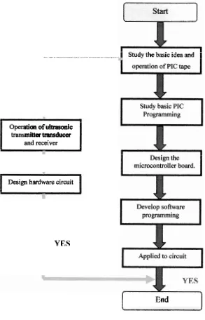
Flow chart of scope of work
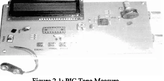
PIC Tape Measure
Electronic Tape measure
Pin description
The internal reset circuit
The comparison between microprocessor
And microcontroller
Harvard architecture block diagram
Types of PICs device from Microchip
Connecting the oscillator
Connecting resonator to microcontroller
RC Oscillator
Ultrasonic transmitter and receiver transducer
Ultrasonic Transducer
LCD Display
LCD Block Diagram
IC LM 358P
Pin description
Symbol (each amplifier)
Block Diagram of PIC Tape Measure
Flow chart of project methodology
xiii
LCD display 28
Ultrasonic transducer 3 1
Circuit diagram 36
PIC tape measure PCB topside component layout,
intenviring,and copper foil master pattern 37
PIC tape measure PCB topside component layout,
interwiring, and copper foil master pattern 37
Circuit power supply 3 8
Circuit Board 41
Test the circuit 41
Display the result 1 42
Display the result 2 42
Display the send button 44
Display the saved button 44
Display the mask button 45
Display the store button 45
xiv
LIST OF ABBREVIATION
AC AID CPU DIA DDRAM DR EEPROM I10 LCD MCLR OSC PCB PIC PSM RAM RC RS RISC ROM Address Counter
analog to digital
Central Processing Unit
Digital to analog
Display data ram
Data register
Electrically Erasable Programmable Read-Only Memory
Input/Output
Liquid Crystal Display
Master Clear
Oscillator
Printed Circuit Board
Peripheral Interface Controller
Projek Sarjana Muda
Random-Access Memory
Resistor-Capacitor
Register selector
Reduced Instruction Set Computer
CHAPTER 1
INTRODUCTION
1.1 INTRODUCTION
In this chapter introduction is made on some general information about PIC Tape
Measure, basic block transmitter, receiver, problem statement, objectives and the scope
of the project.
PIC tape measure is an efficient way to detect distance and check measure value
that is stored in memory, where the device can record and recall 32 distance
measurements, allowing several readings to be taken before copying them to paper.
Besides that, the devices have four switches button and switch pressed while switching
on
Send
-
Basic correction mode.Store
-
EEPROM measurement clear (timing factors untouched).Mask
-
Mask correction mode.Recall
-
clear entire EEPROM data and set default timing factors.The PIC microcontroller (IC2) is the mastermind that controls the whole
40 kHz pulses via the ultrasonic transmitting transducer TX. The pulses are accurately
generated.
The objective of this project is to create one device can detect distance something
object further get keep stated information by using PIC 16F84A. Than that, information
can in display by using LCD screen on circuit.
1 3 SCOPES OF WORK
While doing the project, the scope of work plays a very important role. In order
to do in guideline method, student should fulfill the project requirement. The scope of
this project is listed as below:
i. To study the basic idea and operation of PIC tape measure.
ii. To identifjl the suitable type of PIC microcontroller for the project and design
the microcontroller board.
iii
.
To study the operation of ultrasonic transmitter transducer and receiversensor and its implementation into circuit.
iv To develop between hardware circuit and software programming
. - -. - - - +. -- -- -
-
- - Study the basic idea andI
Operation of ultrasonic transmitter transducerand receiver
I
Design hardware circuit
I
YES
[image:19.604.130.423.108.564.2]I
EndI
1.4 PROBLEM STATEMENTS
Mostly job which involves measurement still using equipment manual to take
reading something distance as ruler etc. This process indirectly will take long time
before something reading obtainable.
Measurement manually very limited to specific location, where ideal when
taking measurement in difficult to access locations and terms of security would be
unsafe his example measurement in the place high. Besides that, reading take unable in
keep and must writing manually before reading further taken.
Caused problem that, PIC tape measure is necessary to do process of
measurement quickly and accurate without should do measurement manually. It also has
the advantage to store information as many as 32 memories at one time.
1.5 REPORT STRUCTURE
The report overall consists of five chapters. Following is an each chapter
description in this thesis.
Chapter 1 is delivering term of computerized room control. It also contains
objective, scopes of works, and problem statement of the project.
Chapter 2 is a literature review on theoretical concepts applied in this project.
The chapter consist explanation about what is PIC tape measure and differentiate with
existing of tape measure system other. The type of PIC chosen, suitable components and
sensor also been discussed.
Chapter 3 is Methodology. It is important part of the whole project because it
shows out how is the project's activity developed for Chapter 3. Thus, it is divided in
overview of microcontroller, circuit and PCB fabrication. It also contains some of the
reason why have chosen the hardware and a list of typical tools and approaches used in
this project. For the software part, it discuss about the software development of the
project. The process also stated h m download the program into the PIC microcontroller
through programmer board.
In Chapter 4, all the analysis result from the hardware and software experiments
is included in the form of table, and discussion.
Chapter 5 is the last chapter that will be the summary of the whole project. The
problems facing during work progress also will be discussed in this chapter. Beside it
CHAPTER 2
LITERATURE REVIEW
2.1
TAPE
MEASURE FOR DETECT DISTANCETape measure is device that can record and recall 30 Or 32 distance
measurements, allowing several readings to be taken before copying them to paper.
These measurements are displayed on the X2 16-character 2 line LCD (liquid crystal
display module). Meters are shown top left, followed by letters "mt", Feet and inches are
[image:22.603.211.480.507.640.2]shown bottom left, complete with letters of "ft" and "in".
2.2
CURRENT
SIMILAR PRODUCTSCurrently there are product in market with features of detect distance, but stated
product sends out narrow beams of sound waves that bounce off solid objects back to the
hand-held receiver. Custom electronics and a microprocessor then convert elapsed time
into a distance measurement and display it on the LCD. When used with its electronic
[image:23.604.223.433.255.452.2]target, the Combo PRO model uses both sound waves and an i n h e d beam 181
Figure 2.2: Electronic Tape measure
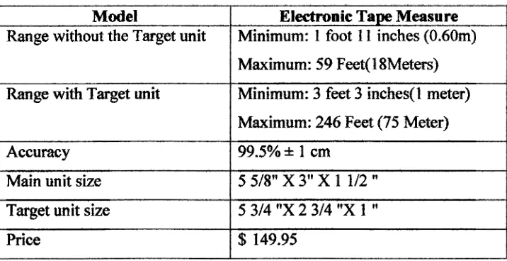
Table 2.1: Specification of Electronic Tape Measure
Model
Range without the Target unit
Range with Target unit
Accuracy
Main unit size
Target unit size
Price
Electronic Tape Measure
Minimum: 1 foot I I inches (0.60m)
Maximum: 59 Feet(l8Meters)
Minimum: 3 feet 3 inches(1 meter)
Maximum: 246 Feet (75 Meter)
99.5%
*
1 cm5
5/8"X3"X
1 112"5
314"X
2 314"X
1"
[image:23.604.152.510.528.712.2]23
WHAT ISTAPE
MEASURE?
Tape measure is the device can detect distance, where it uses transmitter detector
and receiver to take reading and further display to LCD.
The device good is, user can detect distance easily without doing measurement.
User can also adjust unit is wanted. The devices also afford to keep as many as 32
memories as savings. Besides that the devices has also h c t i o n as recall, and mask.
2.4 MICROCONTROLLER
Microcontroller is an integrated circuit, which all the component of the
microcomputer system combined together onto it. It is also represented a key impact
technology for 21st century. Microcontroller provide inexpensive, programmable logic
control and interfacing to external devices. The microcontroller's ability to store and run
unique programs makes it extremely versatile. For example, a microcontroller is
programmed to make decision (perform function) based on predetermined situations
(VO line logic) and selections. The microcontroller's ability to perform mathematic and
logic functions allows it to mimic sophisticated logic and electronic circuit [4].
The basic microcontroller features contain of central processing unit (CPU),
random access memory (RAM), read only memory (ROM), electrically erasable programmable read only memory (EEPROM), input/output (110) lines, serial and
parallel parts, timers, and other built-in peripherals, such as analog to digital (A/D) and