UNIVERSITI TEKNIKAL MALAYSIA MELAKA
MODIFICATION OF HEADLIGHT INTENSITY CONTROL
BASED ON DISTANCE BY USING BLUETOOTH
This report is submitted in accordance with the requirement of the Universiti Teknikal Malaysia Melaka (UTeM) for the Bachelor of Electronic Engineering
Technology (Telecommunication) with Honours.
by
TEO HUEI BOON B071410260 940705-01-6062
UNIVERSITI TEKNIKAL MALAYSIA MELAKA
BORANG PENGESAHAN STATUS LAPORAN PROJEK SARJANA MUDA
TAJUK: MODIFICATION OF HEADLIGHT INTENSITY CONTROL BASED ON DISTANCE BY USING BLUETOOTH
SESI PENGAJIAN: 2017/18 Semester 2
Saya TEO HUEI BOON
mengaku membenarkan Laporan PSM ini disimpan di Perpustakaan Universiti Teknikal Malaysia Melaka (UTeM) dengan syarat-syarat kegunaan seperti berikut:
1. Laporan PSM adalah hak milik Universiti Teknikal Malaysia Melaka dan penulis. 2. Perpustakaan Universiti Teknikal Malaysia Melaka dibenarkan membuat salinan untuk
tujuan pengajian sahaja dengan izin penulis.
3. Perpustakaan dibenarkan membuat salinan laporan PSM ini sebagai bahan pertukaran antara institusi pengajian tinggi.
4. **Sila tandakan ( )
SULIT
TERHAD
TIDAK TERHAD
(Mengandungi maklumat yang berdarjah keselamatan atau kepentingan Malaysia sebagaimana yang termaktub dalam AKTA RAHSIA RASMI 1972)
(Mengandungi maklumat TERHAD yang telah ditentukan oleh organisasi/badan di mana penyelidikan dijalankan)
Alamat Tetap:
NO. 3, JALAN CERMAI 2,
TAMAN SURIA,
86000 KLUANG, JOHOR.
Tarikh: ________________________
Disahkan oleh:
Cop Rasmi:
Tarikh: _______________________
i
DECLARATION
I hereby, declared this report entitled “MODIFICATION OF HEADLIGHT INTENSITY CONTROL BASED ON DISTANCE BY USING BLUETOOTH”
is the results of my own research except as cited in references.
Signature : …………..….………
Author’s Name : ……….………..
ii
APPROVAL
This report is submitted to the Faculty of Engineering Technology of UTeM as a partial fulfilment of the requirements for the degree of Bachelor of Electronic Engineering Technology (Telecommunications) with Honours. The member of the supervisory is as follow:
i
ABSTRAK
ii
ABSTRACT
iii
DEDICATIONS
To my beloved parents
To my respected supervisor and all lecturers And not forgetting to all my friends
For their
iv
ACKNOWLEDGEMENT
v
TABLE OF CONTENT
Abstrak i
Abstract ii
Dedication iii
Acknowledgement iv
Table of Content v
List of Tables ix
List of Figures x
CHAPTER 1: INTRODUCTION 1
1.1 Background 1
1.2 Problem Statement 3
1.3 Objective 4
1.4 Scope 4
CHAPTER 2: LITERATURE REVIEW 6
2.1 Introduction 6
2.2 Bluetooth 6
2.2.1 History of Bluetooth 6
2.2.2 OSI network Model 7
2.2.3 Electromagnetic Frequency Spectrum 8
2.2.4 Spread Spectrum 11
2.2.4.1 FHSS 11
2.2.4.2 DSSS 12
2.2.5 Radio Specification 13
2.2.5.1 GFSK 13
2.2.5.2 Basic Rate and EDR 13
2.2.5.3 LE Data Rate 14
2.2.5.4 TDD 15
2.2.5.5 CDMA 15
vi 2.2.6 Comparison between Short Range Frequencies 16
2.2.7 WPAN 16
2.2.8 Protocol Stack 17
2.2.8.1 Controller 18
2.2.8.2 Physical Layer 19
2.2.8.3 Link Controller 20
2.2.8.4 Baseband Resource Manager 20
2.2.8.5 Link Manager 22
2.2.8.6 AMP MAC, AMP PAL 23
2.2.8.7 Device Manager 23
2.2.8.8 HCI 23
2.2.8.9 L2CAP 23
2.2.8.10 SMP 24
2.2.8.11 STP and ATT 24
2.2.8.12 GATT 24
2.2.8.13 GAP 25
2.2.8.14 AMP Manager 25
2.2.9 Bluetooth Profile 25
2.2.10 Type of Bluetooth 26
2.2.11 Specification of Bluetooth 27
2.3 Car Headlamp 30
2.3.1 History of Car Headlamp 30
2.3.2 Component of Car Headlamp 31
2.3.2.1 Casing 32
2.3.2.2 Reflector 32
2.3.2.3 Bezel 33
2.3.2.4 Lens 33
2.3.2.5 Bulbs 34
2.3.3 Car Light Sources 34
2.3.3.1 Halogen 34
2.3.3.2 HID 35
2.3.3.3 LED 37
vii
2.4 Arduino 40
2.4.1 History of Arduino 41
2.4.2 Arduino UNO 41
2.5 Comparison between Similar Method 43
2.5.1 LDR Based Intensity Control 43
2.5.2 Fuzzy Logic Based Intensity Control 44
2.5.3 WSN Based Intensity Control 45
2.5.4 IR Transmitter-Receiver 46
2.5.5 Camera Based Intensity Control 47
2.5.6 PWM Based Intensity Control 47
CHAPTER 3: METHODOLOGY 49
3.1 Introduction 49
3.2 Planning 49
3.2.1 Data Collection 49
3.2.2 Flow Chart 50
3.3 Design 51
3.3.1 Block Diagram of System Operation 51
3.3.2 Flow Chart of the Headlight Intensity Control System 52
3.4 Implementation 53
3.4.1 Project Implementation 53
3.4.2 Hardware Implementation 53
3.4.2.1 Bluetooth Module JDY-08 53
3.4.2.2 Arduino UNO 54
3.4.2.3 LEDs 54
3.4.2.4 Power Source 54
3.4.2.5 220 Ohm Resistor 55
3.4.2.6 Jumper Wires 55
3.4.2.7 Breadboard 56
3.4.2.8 Car Prototype 56
3.4.3 Software Implementation 57
3.4.3.1 EasyEDA 57
viii
3.4.4 Circuit Design 58
3.4.5 Programming Coding 59
3.4.5.1 Coding for Entering AT Command of Bluetooth Module 59
3.4.5.2 Coding of the System 60
3.4.6 Circuit Prototype 61
CHAPTER 4: RESULT & DISCUSSION 62
4.1 Introduction 62
4.2 Result 62
4.3 Overall Project Operation 63
4.4 Analysis Result 68
4.5 Discussion 71
4.6 Limitation 72
CHAPTER 5: CONCLUSION & FUTURE WORK 73
5.1 Introduction 73
5.2 Conclusion 73
5.3 Future Recommendation 74
ix
LIST OF TABLES
1.1 Road accident data in Malaysia from 1997 to 2016 3
2.1 7 layers of OSI model 7
2.2 Electromagnetic frequency spectrum 8
2.3 Radio Frequency Spectrum Regulatory Authorities 10
2.4 FCC Specification of Bluetooth Low Energy 10
2.5 Properties of LE PHYs 14
2.6 Comparison between short range wireless technologies 16
2.7 Power Classes 19
2.8 Basic Bluetooth radio and baseband parameters 20
2.9 Bluetooth operational state 21
2.10 Type and Specification of Bluetooth 27
2.11 Comparison between Halogen and HID 36
2.12 Comparison of different type of bulbs 38
2.13 Specification of Arduino UNO 42
4.1 Range of Bluetooth module based on different transmit power 68 4.2 The performance of the system based on different transmit power and
x
LIST OF FIGURES
1.1 Low Beam 2
1.2 High Beam 2
2.1 The Logo of Bluetooth 6
2.2 Example of Frequency Hopping Spread Spectrum 12
2.3 Example of Direct Sequence Spread Spectrum 12
2.4 Basic rate packet format 14
2.5 EDR packet format 14
2.6 Bluetooth Core System 17
2.7 Bluetooth core system architecture 18
2.8 Bluetooth Operational State 22
2.9 Bluetooth Profile 26
2.10 An example of Old Headlamp 30
2.11 An example of New Headlamp 31
2.12 Headlamp basic components 31
2.13 Main components of Halogen bulb 35
2.14 Main components of HID 35
2.15 An indication of the colour temperature spectrum 37
2.16 Main component of Basic LED 38
2.17 Component of laser light in BMW i8 39
2.18 Laser light in BMW i8 39
2.19 The operation of a laser light 40
2.20 Comparison of laser light and the standard light 40
2.21 Arduino UNO 41
2.22 LDR based intensity control 43
2.23 Fuzzy logic based intensity control 44
2.24 Wireless Sensor Network based intensity control 45 2.25 Intensity control by using IR transmitter-receiver 46
2.26 Camera based intensity control 47
xi
3.1 Flow chart of planning of the project 50
3.2 Block diagram of the system operation 51
3.3 Flow Chart of the operation of the system 52
3.4 Example of Bluetooth Module 53
3.5 Example of Arduino UNO 54
3.6 LEDs 54
3.7 Resistors 55
3.8 Male to male jumper wire 55
3.9 Male to female jumper wire 56
3.10 Breadboard 56
3.11 Car Prototype 56
3.12 Logo for software EasyEDA 57
3.13 Arduino 1.8.3 57
3.14 Schematic circuit design 58
3.15 AT command coding 59
3.16 Headlight intensity control system coding 60
3.17 Circuit Prototype 61
4.1 Project design 63
4.2 Both cars with circuit met each other 63
4.3 Condition when both circuit met each other 64
4.4 High state for built in LED at PIN 13 64
4.5 Both cars apart to each other 65
4.6 Both cars are moving apart each other 65
4.7 The condition while both circuits are placed apart 66 4.8 Condition when one of the system is power off 66 4.9 Condition when Bluetooth module is detected 67 4.10 Condition when no detection on Bluetooth module 67 4.11 Graph of connection range against transmit power 68 4.12 Graph of connection distance against speed based on different transmit
1
CHAPTER 1
INTRODUCTION
1.1 Background
Nowadays, technology is developing and becomes more advance to improve and comfort human lifestyle. Humans rely on technology. For instant, people use technology in communication, transportation, and entertainment. Wireless communication is one of the technology which using radio waves to transfer information without using any cable. This technology is usually used in telecommunication system for transmit and receive signals.
Bluetooth is one of the wireless technologies which can transfer information with a short range. Bluetooth is commonly used in the electronic devices such as computer, mobile device, and entertainment devices. It costs low and easy to find in the market. In this project, Bluetooth will be applied in a car to control the headlamp of the car.
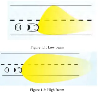
Car is very common for people in this century. It can be said that there is at least one car in a family. The safety of a car is always concerned for the car buyer and the car manufacturer. Roughly one third of all traffic accidents happen after dark, even though there is considerably less traffic at night than during the day. Accidents during the hours of darkness also result in a particularly high proportion of fatalities (the risk of getting killed in an accident at night is almost twice as high as during the day) (Nutt & Kher 2012). It may cause by poor lighting condition while driving.
[image:19.595.167.483.132.446.2]
2 provide significantly more light and are use to illuminate the vehicle’s forward path when other vehicles are not present (Asaduzzaman et al. 2013).
Figure 1.1: Low beam
Figure 1.2: High Beam
However, some people may accidently switch on the high beam and they do not realise. It causes other road users that opposite to them cannot see clearly due blindness while driving. It may harm others eyes and causes accident. Therefore, an automatic switching high beam and low beam is needed to improve safety to the other road users and give a convenient to the drivers.
[image:19.595.192.476.136.259.2]
3
1.2 Problem Statement
Accidents on road always happen. Many lives are lost due to the careless of road users. Not only day time, accident also happens at night although there is less traffic. One of the reasons that cause accident at night is the poor lighting condition. Drivers may not have a clear illumination. Hence, headlamp is designed to improve the visibility of the drivers. The illumination had improved for the drivers but it also reduces the visibility of the opposite road users.
Drivers usually use low beam headlamp to illuminate the surroundings on the road and use the high beam headlamp while the road surroundings is too dazzling. People may accidently switch on the headlamp from low beam to high beam while driving which will actually harm the eyes of road users that are driving in front of them. This is due to people will have some moment of blindness when the facing a strong light suddenly. It makes others can’t see clearly through their sight.
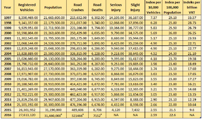
[image:20.595.115.529.429.676.2]Table below shows that the general road accident data in Malaysia from 1997 to 2016 (Anon n.d.).
4 e = estimated value from Department of Statistics Malaysia
a = media statement
NA = Not available (The official figures are not available yet) vkt = vehicle kilometres traveled
1.3 Objectives
The objectives of this project based on the problem statement is
1. To study the concept of car headlight intensity control using Bluetooth
2. To design an automatic headlight intensity system by using Bluetooth 3. To improve the safety of road user
In this project, the objectives include of study the concept of car headlight intensity control using Bluetooth. In this part, the signal of transmitting and receiving will be demonstrated. The operation of Bluetooth in transmit and receive signal also will be shown. The second objective is to design an automatic headlight intensity system based on Bluetooth. The third purpose is to improve the safety of road user by using this product.
1.4 Scope
The project has divided into two parts. The first part of the project is to demonstrate the signal from transmitting and receiving it between both cars in a certain distance by using Bluetooth. The second part is to design an automatic lighting system after detect the signal from other cars. The project will be made in a prototype. This project will mainly use remote control cars, Bluetooth transmitter and receiver, Arduino UNO, and LEDs.
5 under ideal circumference. The range between Bluetooth and the time of the Bluetooth to react will be maximize and minimize.
6
CHAPTER 2
LITERATURE REVIEW
2.1 Introduction
In this chapter, literature review will be covered. All of the research and information that related to this project will be studied and recorded in this chapter. The project title is Modification of Car Headlight Intensity Based On Distance by Using Bluetooth. So in this chapter, all information and researches about history, operation, and development of Bluetooth technology and car headlamp will be listed out.
2.2 Bluetooth
Figure 2.1: The Logo of Bluetooth
Bluetooth is a wireless technology with short range radio frequency which is designed for communication between devices without using any cable or wire.
2.2.1 History of Bluetooth
7 IBM, Nokia and Intel (Verma et al. 2015). This five companies form a group which named the Bluetooth Special Industry Group (SIG) to build up the Bluetooth with 2.4GHz ISM (Industrial, Science, Medical) band. The Bluetooth specification was built up and introduced in 1994. The developers were Jaap Haartsen and Sven Mattisson in Sweden. Bluetooth is specified depends on frequency-hopping spread spectrum technology (Anon n.d.). The name of Bluetooth is officially adopted in 20 May, 1998. The Bluetooth 1.0 specification was released in 1999 (Anon n.d.).
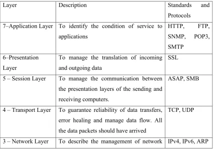
2.2.2 OSI Network Model
Open Systems Interconnect (OSI) model is used to give a parameter for the development of principles for interconnecting computing devices. It separates between device to device connections into seven layers.
Table below shows the description and the standard and protocols used in each layer.
Layer Description Standards and
Protocols 7–Application Layer To identify the condition of service to
applications
HTTP, FTP, SNMP, POP3, SMTP
6–Presentation Layer
To manage the translation of incoming and outgoing data
SSL
5 – Session Layer To manage the communication between the presentation layers of the sending and receiving computers.
ASAP, SMB
4 – Transport Layer To guarantee reliability of data transfers, error healing and manage data flow. All the data packets should have arrived
TCP, UDP
[image:24.595.108.533.445.742.2]