THERMOELECTRIC POWERED HIGH TEMPERATURE USING BOOST CONVERTER
MUHAMAD KAMAL HAFIZ BIN MOHD ANUAR
i
THERMOELECTRIC POWERED HIGH TEMPERATURE USING BOOST
CONVERTER
MUHAMAD KAMAL HAFIZ BIN MOHD ANUAR
This Report Is Submitted In Partial Fulfillment Of Requirement For The Bachelor
Degree of Electonic Engineering (Industrial Electronic)
Fakulti Kejuruteraan Elektronik dan Kejuruteraan Komputer
Universiti Teknikal Malaysia Melaka
vii
ABSTRACT
This project introduces a green technology method to monitor power transformer health condition using heat energy harvesting technique through the Thermoelectric Power Generator (TEG).This project focused on the conversion energy stage from the transformer in electrical subsystem. The ambient heat energy from power transformer will be harvested from TEG. Since the TEG generates very small voltage within in 0.2V to 0.8V, therefore a boost converter is needed to increase the voltage output. The main objective of this project is to design the dc- to dc boost converter in order to increase and stabilize the voltage from TEG. This dc- to dc boost converter is able to increase the voltage from 0.8V up to 5V to power up the small electronic devices such as microcontroller circuit and driven sensors for monitoring purpose. The overall project is an alternative system using harvesting energy by reducing the manpower and eliminates the needs to replace battery.
viii
ABSTRAK
Projek ini memperkenalkan kaedah teknologi hijau untuk memantau tahap keadaan suhu semasa pengubah kuasa menggunakan kaedah penuaian tenaga haba melalui Thermoelectric Power Generator (TEG).Projek ini menjurus kepada peringkat penukaran tenaga daripada pengubah pada. Tenaga haba sekeliling dari pengubah kuasa akan dituai dari TEG. Oleh kerana TEG menghasilkan voltan yang sangat kecil diantara V hingga 0.8V, maka peningkat voltan diperlukan untuk
TABLE OF CONTENTS
CHAPTER TITLE PAGE
PROJECT TITLE i
REPORT STATUS VALIDATION FORM ii
DECLARATION iii
SUPERVISOR DECLARATION iv
DEDICATION v
ACKNOWLEDGEMENT vi
ABSTRACT vii
ABSTRAK viii
TABLE OF CONTENTS x
LIST OF TABLE xiii
I INTRODUCTION 1
1.1 Project Overview 1
1.2 Objectives
1.3 Problem Statement
2
3
1.4 Scope of Project
1.5 Project Significant
3
4
II LITERATURE REVIEW 5
2.1 Infrared Thermography 6
2.2 Fundamental of Thermoelectric Generator
2.2.1 The Physics of Thermoelectric Generation
2.2.2 The Reversed Seebeck Effect
7
2.3 DC to DC Converter
2.3.1 Principle of DC-DC Converters
2.3.2 Categories and Topologies of DC-DC Converters
12
2.4 MAX 757
2.4.1 Pin Diagram and Pin Description
2.4.2 Operation of MAX757
III METHODOLOGY 18 3.1 Phase 1: Literature Review
3.1.1 Step-Up Dc-Dc Converter Using MAX757
19
3.2 Phase 2: Design Process 20
3.2.1Component Searching
3.2.2 Simulation
3.2.3 Hardware Design
3.3 Phase 3: Implementation 23
3.3.1 Schematic Design
3.4 Phase 4: Validation 25
3.4.1 PCB layout
3.5 Phase 5: Maintenance 27
IV RESULTS AND ANALYSIS 28
4.1 Introduction 28
4.2 Functional Block Diagram 29
4.3 Testing Equipment 30
4.4 Procedure Design 31
4.4.2 Low Battery Detection
4.4.3 Inductor Selection
4.4.4 Rectifier Diode
4.5Hardware Results 34
4.6 Results Analysis 36
4.7 Final Product
4.8 Overall Discussion
42
43
V DISCUSSION & CONCLUSION 44
5.1 Conclusion 44
5.2 Recommendation 45
REFERENCES 46
APPENDICES 48
Appendix A
Appendix B
48
LIST OF TABLE
NO TITLE PAGE
2.1 Seebeck Coefficients For Some Common Elements 9
2.2 Conversion Ratio Of Non-Isolating DC-DC Converters 15
2.3 Pin Description 17
4.1 Input Voltage and Output Voltage Reading 39
LIST OF FIGURE
NO TITLE PAGE
2.1 Transformer condition using IRT 7
2.2 Simplified illustration of TEG 8
2.3 Simplified topologies of non-isolating converters 14
2.4 Basic Application Circuit of MAX757 16
2.5 Pin Diagram of MAX757 16
3.1 Waterfall Model 18
3.2 Analysis / Requirement Flowchart 20
3.3 Design Flowchart 21
3.4 Hardware Design 22
3.5 Implementation Flowchart 23
3.6 Schematic Design 24
3.7 Validation Flowchart 25
3.8 Refined schematic design 26
3.9 PCB layout 26
3.10 Maintenance Flowchart 27
4.1 System Structures of the Overall Project 29
4.3 Simulation of Adjustable Output Step-up DC-DC Converter 34
4.4 The PCB layout 35
4.5 Etched board from the top view 35
4.6 Etched board from the bottom view 35
4.7 Current, I(Amp) Vs Voltage, V(Volt) 36
4.8 MPPT(Watt) Vs Voltage, V(Volts) 37
4.9 Output Voltage, Vout (Volt) vs Input Voltage, Vin (Volt) 38
4.10 Output Voltage, V (Volt) vsTemperature,°C(Celc) 40
1
CHAPTER I
INTRODUCTION
1.1 Project Overview
Currently, the use of renewable energy technology and smart grid technology based technique has a vast potential in energy market. There is an increase in renewable energy source particularly in the applications of high energy levels in transmission and distribution [1].This is due to its advantages in term of green technology and environmentally friendly. In the distribution system, equipment like power transformer is still
be the main component, although there has of new technology in the smart grid system.
2
condition of power transformer. Obviously appropriate care and health monitoring of these assets are necessary in order to estimate and predict their live spans.The monitoring should be done over regular time intervals. Failure of power transformers may lead to excessive costs.
Historically, the way to monitor power transformer has started to evolve from typical monitoring technique to the use of sensor. In line with the green technology, the new development of using energy harvesting technology to power up sensors network for the monitoring purpose is proposed. The ambient heat energy from power transformer will be harvested from thermoelectric generator (TEG) to power up power electronic compensator and driven sensors.
1.2 Objectives
In order for the project to be successfully implemented, the following objectives are required to be achieved:
To design the DC-to-DC boost converter in order to increase and stabilize the
power from TEG.
To analyze and study the characteristic of thermoelectric power generator
(TEG) and output range produced from boost converter whether it capable to activated at least the small electronic devices.
To demonstrate how boost converter can boost the electrical energy from the
3
1.3 Problem Statement
Current development to monitoring the health condition of transformer is using infrared thermography (IRT).This technique has been developing by TNB Berhad. But there are some disadvantages by using this type of technique which are images can be difficult to interpret accurately when based upon certain objects, specifically objects with erratic temperatures, although this problem is reduced in active thermal imaging. Besides that, if temperatures are very close in range, infrared imaging can lead to misreading information taken in from the camera; objects can become indistinguishable. The current technology in thermography only allows for imaging to be applied to surface temperatures. The downside to thermography is the price tag that is associated with thermo-imaging equipment. This equipment is rarely used by anybody other than large companies, public services, or educational institutions due to the price that it costs to purchase equipment.[2]
Based on this problem, the new technique has been introduced to overcome the problem by using the thermoelectric generator which is 100% green technology and affordable price.
1.4 Scope Of Project
This project focused on stabilize and boost the output voltage from TEG .This project primarily covered on the several parts, which are:
Identify the characteristics of Thermoelectric Power Generator (TEG) Designing DC- to- DC Boost Converter
4
1.5 Project Significant
This system can be operate in an autonomous and self-powered manner. This system can increase the very low voltage in order to power up the
macro scale devices.
This system using energy harvesting technology to power up sensors
5
CHAPTER II
LITERATURE REVIEW
6
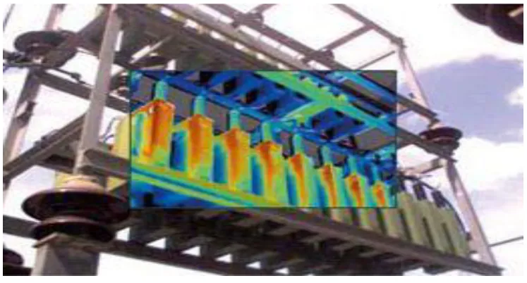
2.1 Infrared Thermography (IRT).
The project from TNB is developing transformer monitoring method by using the infrared thermography (IRT). Infrared thermography (IRT) method used a Thermographic cameras detect radiation in the infrared range of the electromagnetic spectrum (roughly 9,000–14,000 nanometers or 9–14 µm) and produce images of that radiation, called thermograms. Since infrared radiation is emitted by all objects above absolute zero according to the black body radiation law, thermography makes it possible to see one's environment with or without visible illumination. The amount of radiation emitted by an object increases with temperature; therefore, thermography allows one to see variations in temperature. When viewed through a thermal imaging camera, warm objects stand out well against cooler backgrounds; humans and other warm-blooded animals become easily visible against the environment, day or night. As a result, thermography is particularly useful to military and other users of surveillance cameras.
The appearance and operation of a modern thermographic camera is often similar to a camcorder. Often the live thermogram reveals temperature variations so clearly that a photografh is not necessary for analysis. A recording module is therefore not always built-in. but there are some disadvantages using infrared thermography (IRT) which are:
Quality cameras often have a high price range, cheaper are only 40x40 up to
120x120 pixels.
Images can be difficult to interpret accurately when based upon certain
objects, specifically objects with erratic temperatures, although this problem is reduced in active thermal imaging.
Accurate temperature measurements are hindered by differing emissivity and
reflections from other surfaces.
Most cameras have ±2% accuracy or worse in measurement of temperature
7
[image:23.595.113.487.104.305.2] Only able to directly detect surface temperatures.
Figure 2.1: Transformer condition using IRT
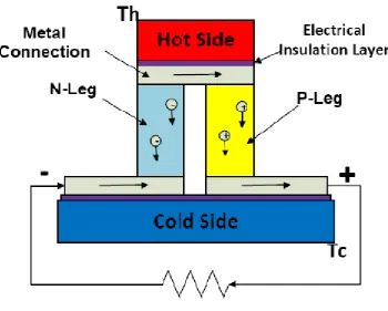
2.2 Fundamental of Thermoelectric Generator
Thermoelectric generator (TEG) is a device that converts thermal energy directly into electrical energy [3]. A typical TEG structure is shown in Figure 2.2. Early TEG devices utilize metallic TE material, whereas more recently manufactured TEGs use alternating n- and p-type semiconductor materials. The TEG structure is consisting of thermoelectric materials which are sandwiched by two heat exchanger plates at its two ends respectively. One of the two exchangers has high temperature, and hence, it is called the hot side of the TEG. The other has low temperature and is called the cold side of the TEG. There are electrical-insulate-thermal-conductive layers between the metal heat exchangers and the TE material. The two ends of n- and p-type legs are electrically connected by metal
8
Figure 2.2 Simplified illustration of TEG
2.2.1 The Physics of Thermoelectric Generation