Torsional resistance of high-strength concrete beams
T. Hossain & P. Mendis
University of Melbourne, Victoria, Australia
T. Aravinthan & G. Baker
University of Southern Queensland, Queensland, Australia
1 INTRODUCTION
In recent years, many theories have been devel-oped for calculating the torsional strengths of mem-bers with both longitudinal steel and stirrups. The most recognized theoretical models are the space truss model and the skew-bending theory. It is found that the skew-bending theory overestimates the cracking strength of the torsion of RC beams by considering the contribution of concrete (Fang & Shiau 2004). Collins & Mitchell (1974, 1980) ex-tended the truss model to include the capacity of concrete and the orientation of the compression con-crete members, and named this the diagonal com-pression field theory. One key assumption of their theory was that for a solid section subjected to sion, the concrete core does not contribute to the tor-sional resistance. Accordingly, this model does not consider the advantage of the use of HSC. Hsu & Mo (1985) further developed the space truss model to the softened truss model, which accounts for the softening of the cracked concrete. For a low-strength concrete, their model gives a good description of the ascending branch and the first part of the descending branch of the uniaxial stress-strain curve (Rasmus-sen & Baker 1995b). However, the uniaxial stress-strain curve for concrete changes dramatically when comparing a NSC to a HSC. Hence, it is not obvious that the model can be extrapolated from NSC to the HSC range. Similarly, aggregate interlock is not in-cluded in any of these above models, which is a very important phenomenon in HSC. This is because
high-strength concretes are much more brittle than normal strength concretes, with less load carrying capacity once the peak load is reached. Due to the similarity of the strengths in aggregates and that of the surrounding concrete, the failure surfaces are smooth and devoid of aggregate interlock, which re-duces the shear resistance in the case of HSC (Attard & Mendis 1993).
While HSC has been recently and increasingly used in bridges and buildings, the available theoreti-cal models regarding the behaviour and design code provisions of torsion in AS3600-2001 are primarily based on limited experimental work on low strength concrete beams. Therefore, more work is required to safeguard the related designs when the available in-formation is extrapolated to the design of torsional members made of higher strength concrete. Verifica-tion of the applicability of the available theoretical models to higher-strength concrete is also required.
transfer mechanism in HSC; the softening of con-crete in compression; tension; and shear.
2 REVIEW OF THEORETICAL MODELS
2.1 Skew-bending theory
The skew-bending theory was initially proposed by Lessig in 1958 (1959), and had subsequent con-tributions from several researchers in the field. Hsu (1968) made a major contribution to the develop-ment of this theory as it presently stands. He pre-sented the expressions for evaluating the torsional strength of rectangular sections according to the PCA tests.
The basic approach of the skew-bending theory is that the failure of a rectangular section in torsion oc-curs by bending about an axis which is parallel to the wider face of the section and inclined at about 45° to the longitudinal axis of the beam. The tor-sional strength of reinforced concrete members is contributed to by both concrete, Tc and torsional re-inforcement, Ts. But, from the PCA tests by Hsu (1968) on hollow and solid rectangular beams, it was observed that the concrete core does not contribute to the ultimate torsional strength. Later he concluded that the concrete contribution Tc was mainly due to the shear resistance of the diagonal concrete struts.
Based on this approach, the torsional resistance proposed by Hsu (1979) includes the contribution of shear resistance of diagonal concrete struts, axial forces of stirrups, and the dowel forces of the longi-tudinal bars, and can be evaluated as follows:
s f A y x T
Tn = c +αt 1 1 t sy (1)
where Tc = x y
(
2.4 fc′ 32
)
(in lb-in.)6 . 1 2
. 0 1
1
1 ≤
⎟⎟ ⎠ ⎞ ⎜⎜
⎝ ⎛
+ =
x y f
f m
sy ly t
α
x1 = shorter centre-to-centre dimension of closed stirrup; y1 = longer centre-to-centre dimension of closed stirrup
At = area of one leg of a torsional closed stirrup s = spacing of stirrups
fly = yield strength of longitudinal bars fsy = yield strength of closed stirrups
m = ratio of volume of longitudinal bars to volume of stirrups
=
) (
2 ˆ
1
1 y
x A
s A
t l
+
=
l cross-sectional area of longitudinal bars within
the shear-compression zone A
ˆ
2.2 Space truss model with spalling of concrete over
c
The most recognized theoretical mode of pure torsion in reinforced concrete is the space truss model, which was first developed by Rausch (1929), and consists of diagonal struts in the concrete strained by tension in the stirrup and longitudinal re-inforcement. After the cracking of a reinforced con-crete member subjected to pure torsion, the diagonal cracks separate the concrete into a series of concrete struts. In the space truss model the torsion is resisted by compression diagonals, which consist of the con-crete between cracks that spiral around the beam at a constant angle.
Based on an assumed strain distribution in the beam, Collins & Mitchell (1974, 1980) extended the truss model and developed a theory to describe the torque-twist response. Mitchell & Collins (1974) ob-served that the increase in the thickness of the con-crete cover caused spalling and a reduction in the torsional strength. According to this assumption of concrete cover spalling, the ultimate torsional capac-ity of the member is based on the strength of the spalled section. In their theory, based on the knowl-edge of the uni-axial stress-strain curve, a parabolic stress-strain curve of the concrete was given by the following equation:
⎥ ⎥ ⎦ ⎤ ⎢
⎢ ⎣ ⎡
⎟⎟ ⎠ ⎞ ⎜⎜ ⎝ ⎛ − ⎟⎟ ⎠ ⎞ ⎜⎜ ⎝ ⎛ ′ =
2
0 0
2
ε ε ε
εc c
c
c f
f (2)
where
fc = stress in concrete corresponding to the strain εc f'c = compressive strength of concrete
εc = strain in diagonal concrete struts
ε0 = strain at maximum concrete compressive stress The detailed derivation of the equations and the solution technique for the ultimate torsional capacity can be found elsewhere (Mitchell and Collins 1974).
2.3 Softening trussmodel
⎥ ⎥ ⎦ ⎤ ⎢
⎢ ⎣ ⎡
⎟⎟ ⎠ ⎞ ⎜⎜ ⎝ ⎛ − ⎟⎟ ⎠ ⎞ ⎜⎜ ⎝ ⎛ ′ =
2
1 2
o c
o c c
c f
f
ε ε ζ ε ε
(3)
where
fc = average compressive stress in the diagonal con-crete struts
εc = compressive strain in the diagonal concrete struts
εo = strain at maximum stress of non-softened con-crete taken as 0.002 for NSC
ζ = softening coefficient =
3 . 0 2 1
− + +
d d s l
ε ε ε ε
εl= strain in ordinary longitudinal steel εs= strain in stirrups
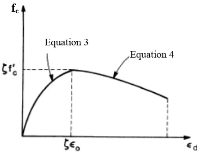
The equation of the descending portion of the stress-strain curve is given as:
⎥ ⎥ ⎦ ⎤ ⎢
⎢ ⎣ ⎡
⎟⎟ ⎠ ⎞ ⎜⎜
⎝ ⎛
− − − =
2
2 1
k o
k c k
c f
f
ε ε
ε ε
(4)
where
fk = ζ f'c = peak softened compressive strength εk = ζεo = softened strain corresponding to peak sof-tened compressive strength
Figure 1. Stress-strain curve for softened concrete
The torque is obtained from equilibrium equa-tions. The detailed derivation of the equations and the solution technique for the ultimate torsional ca-pacity can be found elsewhere (Hsu & Mo 1985, Hsu 1988).
3 AS3600-2001 TORSION DESIGN CRITERIA
The design of reinforced concrete beams sub-jected to pure torsion according to the AS3600 is based on the space truss model, and does not operate with a variable wall-thickness dependent on the con-crete strength and the degree of reinforcement.
Ac-cording to the torsion provision of AS3600, the ul-timate strength of a reinforced concrete beam is derived from the thin-walled tube analogy, assuming it is directly proportional to the amount of rein-forcement as follows:
θ
cot 2
s f A A
Tp = o s ys ≤ 0.08 f'c b2h (5)
where
Ao = area enclosed by shear flow path = xoyo As = area of one leg of closed stirrup
fys = yield strength of closed transverse torsional re-inforcement
s = spacing of stirrup
θ = angle of compression diagonals
b, h = smaller and larger outer dimensions of the cross-section respectively
xo, yo = horizontal and vertical distance between the centre line of the longitudinal corner bars respec-tively
Thus the concrete contribution is ignored after torsional cracking in AS3600, which makes no dis-tinction between the behaviour of normal and high-strength concretes; i.e., there is no advantage in us-ing higher concrete strengths in resistus-ing ultimate torsion.
4 REVIEW OF PAST WORK ON TORSION OF RC BEAMS
In the past, there have been some investigations conducted which study the behaviour of RC beams under pure torsion. Reid & Bridge (1990) have car-ried out theoretical and experimental investigations to assess the behaviour of pre-stressed concrete edge beams heavily loaded in shear and torsion. Their theoretical investigation indicated that torsion would greatly reduce the load-carrying capacity of the beams, and the combined torsion and shear would result in brittle failures. The effect of concrete com-pressive strength on the torsional behaviour of rein-forced concrete beams was investigated by Rasmus-sen & Baker (1994, 1995a, 1995b). The results of that investigation showed a significant effect of con-crete strength on crack width, torsional stiffness, and torsional capacity of the test beams. Koutchoukali & Belarbi (2001) studied the effect of high-strength concrete on the torsional behaviour of RC beams under pure torsion. They found from their study that the torsional capacity of under-reinforced beams is independent of concrete strength, and the amount of longitudinal reinforcement was more effective in controlling crack width than the amount of trans-verse reinforcement. Fang & Shiau (2004) experi-mentally studied the torsional behaviour of normal and high-strength concrete beams under pure tor-sion. Their test results showed that the HSC beams had higher torsional strength and cracked stiffness
fc
Equation 3
[image:3.595.66.260.413.568.2]than the NSC beams which were designed with the same amount of reinforcement. Results of several investigations on the torsional behaviour of normal-strength concrete beams have also been reported (Hsu 1968; Mitchell & Collins 1974; Hsu & Mo 1985). However, no rational method to incorporate the concrete contribution to ultimate torsional strength is proposed in these past works.
5 PARAMETRIC STUDY ON PURE TORSION
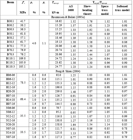
To examine the applicability of the three theoreti-cal models for high-strength concrete, the experi-ments carried out by Rasmussen & Baker (1995a) and Fang & Shiau (2004) were analyzed. The test specimens were of solid rectangular beams failing in pure torsion, and represent all possible reinforce-ment situations and a significant variation in
geo-metric and material parameters. Their experimental results are considered in the correlation between the test and the predicted torsional capacity from the theoretical models, and the effect of concrete strength on ultimate torsional strength. Table 1, Fig-ure 2 and FigFig-ure 3 compare the experimental results with the predicted torsional strength of the tested beams from the literature, using the aforementioned theories.
On the basis of observations and results reported in this paper, it can be seen from Figure 2 and Figure 3 that AS 3600 always overestimates the experimen-tal torsional capacity. Due to the spalling of the con-crete cover, the area enclosed by the centre line of the thickness reduces, resulting in a reduced tor-sional capacity of the section. But the present AS3600 does not operate with this variable wall thickness, which may result in an unconservative
Table 1. Comparison of experimental and calculated torsional strength
Tu(cal)/Tu(exp)
Beam f′c
MPa ρl
% ρt
%
Tu(exp)
kN-m
AS 3600
Skew-bending
theory
Space truss model
Softened truss model
Rasmussen & Baker (1995a)
B30.1 41.7 16.62 1.32 1.76 1.32 1.01
B30.2 38.2 15.29 1.37 1.91 1.23 0.98
B30.3 36.3 15.25 1.33 1.92 1.01 0.91
B50.1 61.8 19.95 1.33 1.50 0.89 0.81
B50.2 57.1 18.46 1.39 1.61 1.12 1.05
B50.3 61.7 19.13 1.38 1.56 0.88 0.86
B70.1 77.3 20.06 1.40 1.50 1.14 0.91
B70.2 76.9 20.74 1.35 1.44 1.10 0.95
B70.3 76.2 20.96 1.35 1.44 1.07 1.03
B110.1 109.8 24.72 1.24 1.24 0.94 0.93
B110.2 105.0 23.62 1.30 1.30 0.96 0.90
B110.3 105.1
4.0 1.1
24.77 1.23 1.24 0.98 0.93
Fang & Shiau (2004)
H06-06 0.6 0.6 92.0 1.25 1.03 0.88 1.01
H06-12 1.2 0.6 115.1 1.01 0.90 0.93 1.04
H12-12 1.2 1.2 155.3 1.50 0.88 0.95 1.05
H12-16 1.6 1.2 196.0 1.15 0.88 0.98 0.97
H20-20
78.5
2.0 2.0 239.0 1.40 1.07 1.11 0.97
H07-10 1.0 0.7 126.7 0.91 0.84 0.86 0.97
H14-10 1.0 1.4 135.2 1.35 1.13 1.03 1.15
H07-16
68.4
1.6 0.7 144.5 0.80 0.73 0.93 0.97
N06-06 0.6 0.6 79.7 1.12 1.03 0.96 1.02
N06-12 1.2 0.6 95.2 0.95 0.97 1.05 1.01
N12-12 1.2 1.2 116.8 1.55 1.07 1.15 0.99
N12-16 1.6 1.2 138.0 1.27 1.16 1.12 0.88
N20-20
35.5
2.0 2.0 158.0 1.64 1.54 1.14 0.85
N07-10 1.0 0.7 111.7 0.81 0.86 0.85 0.78
N14-10 1.0 1.7 125.0 1.13 1.14 0.92 0.79
N07-16
33.5
[image:4.595.59.517.324.805.2]and unsafe prediction of the ultimate torsional ca-pacity. Also, the concrete contribution, is ignored af-ter torsional cracking in AS3600, and is directly proportional to the amount of transverse reinforce-ment. The angle of compression diagonals is also kept constant with the shear formula.
0 0.
1
0 4 8 120
f'c
T
(ca
5 1.5
0 0
l)
/T
(ex
p
)
0 0.5 1 1.5 2 2.5
0 40 80 120
f'c
T
(c
al
)
/T
(e
x
p)
AS3600-2001 Skew-bending theory Space truss model Softening truss model
Figure 2. T(cal)/T(exp) versus concrete compressive strength (Rasmussen & Baker 1995b)
0 0.5 1 1.5 2
0 20 40 60 80 100
f'c
T
(c
a
l)/T
(ex
p
)
AS3600-2001 Skew-bending theory Space truss model Softening truss model
Figure 3. T(cal)/T(exp) versus concrete compressive strength (Fang & Shiau 2004)
It can be seen from Table 1 that the space truss model with spalling of concrete, and the softening truss model, give the best prediction for the ultimate torsional capacity when compared with the experi-mental result, with a mean and a standard deviation of 0.9 and 5.8% for the softened truss model, and 1.05 and 6.8% for the space truss model. On the other hand, skew-bending theory gives reasonable predictions for beams tested by Fang & Shiau (2004), but is unconservative for the beams tested by Rasmussen & Baker (1995a). This is because all the beams tested by Rasmussen & Baker (1995a) were over-reinforced where the failure of the beams re-sulted from the concrete failure. The overestimate of the ultimate strength from the skew-bending theory is because the theory includes the volume of the lon-gitudinal and transverse reinforcements and the con-crete contribution.
It can be seen from Table 1 that for beams with the same reinforcement ratio, the ultimate torsional strength of HSC beams increases approximately 1.2 times than that of NSC beams when the compressive strength of concrete increases from approximately 35 to 78 MPa. This further verified the effect of f′c
on the ultimate torsional capacity. It exhibits that the ultimate torsional strength of RC beams increases as the compressive strength of concrete increases.
Table 2. Comparison of calculated and experimental cracking strength
AS3600 Skew-bending theory Beam f′c
MPa
Tcr(exp)
kN-m Tcr(cal) TTcr(cal)/
cr(exp)
Tcr(cal) Tcr(cal)/
Tcr(exp)
Rasmussen & Baker (1995)
B30.1 41.7 7.18 5.46 0.76 7.58 1.06
B30.2 38.2 6.05 5.22 0.86 7.25 1.20
B30.2 36.3 6.07 5.09 0.84 7.07 1.16
B50.1 61.8 7.43 6.64 0.89 9.22 1.24
B50.2 57.1 6.41 6.38 0.99 8.87 1.38
B50.3 61.7 6.98 6.64 0.95 9.22 1.32
B70.1 77.3 9.27 7.43 0.83 10.32 1.11
B70.2 76.9 9.27 7.43 0.80 10.29 1.11
B70.3 76.2 9.30 7.37 0.79 10.24 1.10
B110.1 109.8 11.46 8.85 0.77 12.29 1.07
B110.2 105.0 9.05 8.66 0.96 12.02 1.33
B110.3 105.1 11.50 8.66 0.75 12.02 1.05
Fang & Shiau (2004)
H06-06 70.6 65.12 0.92 90.45 1.23
H06-12 75.0 65.12 0.87 90.45 1.21
H12-12 77.1 65.12 0.84 90.45 1.17
H12-16 79.3 65.12 0.82 90.45 1.14
H20-20 78.5
76.0 65.12 0.86 90.45 1.19
H07-10 70.5 60.79 0.86 84.43 1.20
H14-10 61.8 60.79 0.98 84.43 1.37
H07-16 68.4
65.3 60.79 0.93 84.43 1.29
N06-06 43.2 43.79 1.01 60.82 1.41
N06-12 51.8 43.79 0.85 60.82 1.17
N12-12 49.3 43.79 0.89 60.82 1.23
N12-16 57.1 43.79 0.77 60.82 1.07
N20-20 35.5
55.0 43.79 0.80 60.82 1.11
N07-10 41.6 42.54 1.02 59.09 1.42
N14-10 41.8 42.54 1.02 59.09 1.41
N07-16 33.5
40.0 42.54 1.06 59.09 1.48
[image:5.595.41.288.9.292.2] [image:5.595.302.569.195.683.2] [image:5.595.56.287.357.505.2]
series are 0.82 for the AS3600 expression, and 1.13 for the skew-bending theory; while for those in the NSC series, the values are 0.88, and 1.23, respec-tively, from Rasmussen & Baker’s (1995a) beams. In the case of Fang & Shiau’s (2004) beams, the mean values of the ratios Tcr(cal)/Tcr(exp) in the HSC series are 0.89 for the AS3600 expression, and 1.23 for the skew-bending theory; while for those in the NSC series, the values are 0.93, and 1.25, respec-tively. So in all cases, whether over-reinforced or under-reinforced, the AS3600 expression underesti-mates the cracking strength, while skew-bending theory overestimates the cracking torque of rein-forced concrete beams. Also, the ratio of ultimate and cracking torsional strength, Tu/Tcr, from Ras-mussen & Baker’s (1995a) beams is 2.61 for NSC and 2.26 for HSC, while the respective values from Fang & Shiau’s (2004) beams are 2.5 and 2.08. This proves that after cracking, the increase in torsional strength for HSC is less than in NSC. This is proba-bly due to the well-known reduced aggregate inter-locking shear resistance mechanism in HSC.
6 LATTICE MODEL
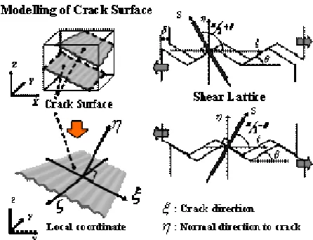
The lattice model was initially developed by Niwa et al. (1994), and can be expressed using a fi-nite element formulation by smearing out concrete and reinforcement lattices into a continuum. The main characteristic of the lattice model is the possi-bility to change the direction of the local coordinate (or the inclination angle of the lattice component) in proportion to the progress of fracture in the connec-tion between the stress field of the global and local coordinate system. This model provides the freedom to change the inclination angle of longitudinal rein-forcement lattice components. Thus it is possible to evaluate the dowel effect by controlling the inclina-tion angles of the reinforcement lattice components. In addition, it is possible to evaluate the resisting mechanism of transverse reinforcement, which may not be vertical. With regard to the resisting mecha-nism of concrete, the shear transfer of the crack sur-face can be evaluated not by using the shear stress-strain relationship, but by using the shear lattice. For each crack surface, two shear lattices S1 and S2 are provided. The shear force along a crack is carried by these shear lattices. The effect of aggregate interlock is dependent on the relative movement of concrete on two sides of the crack and thus S1 and S2 will be-come active as shown in Figure 4. In this shear transfer mode, the roughness of the crack surface is represented by the roughness angle θ of the crack surface. Itoh et al. (2000) suggested a value θ = π/3 for NSC based on a comprehensive study comparing the lattice model and the panel test results of Vec-chio & Collins (1986). For HSC with smoother crack surfaces, a smaller value of θ should be
adopted. A value of π/4 was proposed by Ngo (2005) for the roughness angle.
The technique of the lattice model has been suc-cessfully applied for both normal and high–strength concrete beams subjected to shear, by including a fracture energy based damage model as developed by Hossain (2006). The fracture energy based dam-age model developed in this study is based on the MCFT, reduced fracture energy and variable shear retention factors, which represent the change of ma-terial properties due to the higher strength of con-crete. A linear decreasing function related to the ten-sile strain that is normal to the crack plane is proposed in this study, which takes into account the fact that friction due to the roughness of the crack surface decreases as the opening of the crack in-creases. This improves the damage model, allowing for the correct provision of the secondary mecha-nisms of shear resistance of a structure and account-ing for the well-known experimental observation of the reduced aggregate interlock shear resistance in the case of HSC.
Figure 4. Modelling shear contact area with shear lattices
7 CONCLUSIONS AND RECOMMENDATIONS
Based on the assessment of the theoretical models and AS3600 for rectangular beams under pure tor-sion, the following can be concluded:
1. A higher crack load and higher torsional capac-ity for a given cross-section are obtained using high-strength concrete both from experimental and theo-retical models.
2. Among the three theoretical models used, the space truss model with spalling of the concrete cover and softened truss model give the best estimate of the ultimate torsional strength of test beams.
[image:6.595.324.547.337.508.2]4. HSC provided higher torsional strength than NSC for beams designed with the same amount of reinforcement.
Further research effort remains to be imple-mented to accurately predict the torsional behaviour of high-strength reinforced concrete beams, by tak-ing into account the effects of reduced aggregate in-terlock shear transfer mechanism due to the smooth crack surface in HSC. An advanced method of analysis based on the lattice model can be developed to carry out a rational analysis for torsion up to the ultimate range, to include the important aspects of aggregate interlock and dowel action, which have been ignored in the past for torsional resistance.
REFERENCES
AS 3600 2001. Concrete Structures, Standards Association of Australia, Australia.
Attard, M. M., & Mendis, P. A. 1993. Ductility of
High-Strength Concrete Columns. Australian Civil Engineering
Transactions, The Institute of Engineers, Australia, Vol. CE35, No. 4, October 1993, pp 295-306, 295-306.
Collins, M. P., & Mitchell, D. 1980. Shear and Torsion Design
of Prestressed and Non-Prestressed Concrete Beams. PCI
Journal, 25(5), 32-100.
Fang, I. K., & Shiau, J. K. 2004. Torsional Behavior of
Nor-mal- and High-Strength Concrete Beams. ACI Structural
Journal, 101(3), 304-313.
Hossain, T. 2006. Shear Behaviour of High-Strength Concrete
Beams at Low and High Strain-Rates. PhD Thesis,
Depart-ment of Civil and EnvironDepart-mental Engineering, University of Melbourne. Australia, 289 pp.
Hsu, T. C. 1968. Torsion of Structural Concrete- Behaviour of
Reinforced Concrete Rectangular Members. Torsion of
Structural Concrete, SP-18, American Concrete Institute, Farmington Hills, Mich., 261-306.
Hsu, T. C. 1979. Discussion of ‘Pure Torsion in Rectangular Sections-A Re-examination’ by McMullen, A. E. and
Ran-gan, B. V. Journal of the American Concrete Institute,
Proc., 76(6), 741-746.
Hsu, T. C. 1984. Torsion of Reinforced of Concrete. Van
Nostrand Reinhold, New York, USA, 1-516.
Hsu, T. C., & Mo, Y. L. 1985. Softening of Concrete in
Tor-sional Members-Theory and Tests. ACI Journal, 82(3),
290-303.
Hsu, T. C., and Mo, Y. L. (1985). Softening of Concrete in
Torsional Members-Design Recommendations. ACI
Jour-nal, 82(4), 443-452.
Hsu, T. C. 1988. Softened Truss Model Theory for Shear and
Torsion. ACI Structural Journal, 85(6), 624-635.
Itoh, A., Ishtiaq, A. S., & Tanabe, T. 2000. Expression of the Compression Field Theory Based on the Lattice Equivalent
Continua Model. Transactions of the Japan Concrete
Insti-tute, 22, 427-432.
Koutchoukali, N. E., & Belarbi, G. 2001. Torsion of High-Strength Reinforced Concrete Beams and Minimum
Rein-forcement Requirement. ACI Structural Journal, 98(4),
462-469.
Lessig, N. N. 1959. Determination of Load-Carrying Capacity of Rectangular Reinforced Concrete Elements subjected to
Flexure and Torsion. Concrete and Reinforced Concrete
In-stitute, Trudy No. 5, Moscow, 5-28.
Mitchell, D., & Collins, M. P. 1974. Diagonal Compression Field Theory-A rational Model for Structural Concrete in
Pure Torsion. ACI Journal, Proc., 71(8), 396-408.
Ngo, T. D. 2005. Behaviour of High Strength Concrete subject
to Impulsive Loading. PhD Thesis, Department of Civil and
Environmental Engineering, University of Melbourne. Aus-tralia, 331 pp.
Niwa, J., Choi, I. C., & Tanabe, T. 1994. Analytical Study for
Shear Resisting Mechanism using Lattice Model. JCI
In-ternational workshop on Shear in Concrete Structures, Ja-pan, 130-145.
Rasmussen, L. J., & Baker, G. 1994. Assessment of Torsional Strength in Reinforced Normal and High-Strength Concrete
Beams. Australian Civil Engineering Transactions, IEAust.,
CE36(2), 165-171.
Rasmussen, L. J., & Baker, G. 1995a. Torsion in Reinforced Normal and High-Strength Concrete Beams-Part 1:
Ex-perimental Results. ACI Structural Journal, 92(1), 55-63.
Rasmussen, L. J., & Baker, G. 1995b. Torsion in Reinforced Normal and High-Strength Concrete Beams-Part 2: Theory
and Design. ACI Structural Journal, 92(2), 149-156.
Rausch, E. 1929. Design of Reinforced Concrete in Torsion.
PhD Thesis, Technische Hochshule, Berlin, 53 pp.
Reid, S. G., & Bridge, R. C. 1990. Shear and Torsion in
Rein-forced Concrete Beams. National Conference Publication,
Institute of Engineers, Australia, 90(10), 259-264.
Vecchio, F. J., & Collins, M. P. 1986. Modified Compression Field Theory for Concrete Elements Subjected to Shear.