University of Southern Queensland
Faculty of Engineering and Surveying
An Internet Based SCADA System
A dissertation submitted by
Jason Michael Lynch
in fulfillment of the requirements of
Courses ENG4111 and 4112 Research Project
towards the degree of
Bachelor of Electrical/Electronic Engineering
Abstract
The Supervisory Control and Data Acquisition (SCADA) system has an integral role in modern industry. It provides a link to the electronic controllers used to control factory plant and processes, and is the visible portion of a factory’s Human Machine Interface (HMI) system. It allows a factory operator to control the plant and provides feedback about the current state of the factory processes, including any alarms.
The SCADA system also provides a way for important plant performance information to be obtained for use by managers and engineers at a corporate level. Timely access to this information is important in decision making. With large modern companies being so geographically diverse in the location of individual business units, the Internet has become an important communication channel to allow the exchange of data. This dissertation describes the design of an Internet based SCADA system that allows real-time factory data to be made available to the necessary personnel, regardless of where they may be on the globe.
University of Southern Queensland
Faculty of Engineering and Surveying
ENG4111 & ENG4112 Research Project
Limitations of Use
The Council of the University of Southern Queensland, its Faculty of Engineering and Surveying, and the staff of the University of Southern Queensland, do not accept any responsibility for the truth, accuracy or completeness of material contained within or associated with this dissertation.
Persons using all or any part of this material do so at their own risk, and not at the risk of the Council of the University of Southern Queensland, its Faculty of Engineering and Surveying or the staff of the University of Southern Queensland.
This dissertation reports an educational exercise and has no purpose or validity beyond this exercise. The sole purpose of the course pair entitled ‘Research Project’ is to contribute to the overall education within the student’s chosen degree program. This document, the associated hardware, software, drawings, and other material set out in the associated appendices should not be used for any other purpose: if they are so used, it is entirely at the risk of the user.
Prof G Baker
Dean
Certification
I certify that the ideas, designs and experimental work, results, analyses and conclusions set out in this dissertation are entirely my own effort, except where otherwise indicated and acknowledged.
I further certify that the work is original and has not been previously submitted for assessment in any other course or institution, except where specifically stated.
Jason Michael Lynch
Student Number: 0019722478
__________________________________ Signature
Acknowledgements
I would like to thank the following people for their invaluable assistance and contributions which have aided the success of this project:
Dr. Peng (Paul) Wen (Supervisor) for his guidance during the execution of the project and the preparation of this dissertation.
The staff of Millmerran Operating Company for their assistance during the duration of the project.
Contents
Abstract
...iAcknowledgements
...iv [image:6.612.133.550.290.723.2]Contents ...v
Table of Figures...vii
Chapter 1
...1Introduction
...11.1
Project Objectives
...21.2
Dissertation Layout
...21.3
Chapter Summary
...3Chapter 2
...4SCADA and Web-based SCADA Systems
...42.1
An Industrial Control System
...42.2
SCADA System Description
...62.3
SCADA System Functions
...62.4
Commercial SCADA Systems
...82.5
SCADA System Evolution and IP Convergence
...92.6
Web-Based Implementations
...112.7
Key Issues for an Internet Based SCADA System
...162.8
Chapter Summary
...18Chapter 3
...19Communication over the Internet
...193.1
Overview
...193.2
The Seven Layer OSI Model
...203.3
Sockets and TCP/IP
...223.4
Distributed Component Object Model (DCOM)
...263.5
Hyper Text Transfer Protocol (HTTP)
...263.6
Simple Object Access Protocol (SOAP)
...273.7
XML Web Services
...283.8
Quality of Service of Real-Time Data
...293.10
Chapter Summary
...32Chapter 4
...33Design Methodology
...334.1
Overview
...334.2
Programming Language Considerations
...334.3
Programming in C
...344.4
Programming in C++
...344.5
Programming in Java
...344.6
The .NET Framework
...354.7
Programming Language Selection
...354.8
System Design Alternatives
...364.10
Chapter Summary
...37Chapter 5
...38System Development and Implementation
...385.1
Overall Description
...385.2
Client-Server Interoperability
...385.3
Server Program Function
...395.4
Client Program Function
...425.5
Testing Process
...445.6
Problems Encountered
...455.7
Chapter Summary
...46Chapter 6
...47Conclusions and Recommendations for Future Work
....476.1
Achievement of Objectives
...476.2
Future Work
...48References
...50Appendix A
...52Project Specification
...52Appendix B
...54Server Program Listing
...54PlantData.asmx.vb ...55
PlantData1.vb...57
Appendix C
...66Client Program Listing
...66Main.vb...67
Reference.vb ...71
PlantData.wsdl ...73
Table of Figures
Figure 2.1: General Layout of the Bailey Infi-90 DCS...5Figure 2.2: Example SCADA Display...7
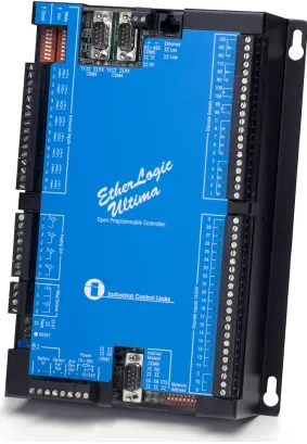
Figure 2.3: PLC with Embedded Web Server...12
Figure 2.4: SCADA Display for a PLC with Embedded Web Server...13
Figure 2.5: Remote Access via a SCADA Service Provider...14
Figure 2.6: Remote and Local Access via a SCADA Service Provider...14
Figure 2.7: Three Tier Client/Server Architecture of System proposed by Gooi, H.B. and Qui, B....15
Figure 2.8: Hardware Layout of System proposed by Gooi, H.B. and Qui, B....16
Figure 3.1: The Seven Layer OSI Model...20
Figure 3.2: The Seven-Layer OSI Model and TCP/IP Suite...23
Figure 3.3: A TCP Segment...24
Figure 3.4: An IP Datagram...25
Figure 3.5: An XML .NET Web Service...29
Figure 4.1: The Visual Studio .NET IDE...36
Chapter 1
Introduction
The Supervisory Control and Data Acquisition (SCADA) system has an integral role in modern industry. It provides a link to the electronic controllers used to control factory plant and processes, and is the visible portion of a factory’s Human Machine Interface (HMI) system. It allows a factory operator to control the plant and provides feedback about the current state of the factory processes, including any alarms.
The SCADA system also provides a way for important plant performance information to be obtained for use by managers and engineers at a corporate level. Timely access to this information is important in decision-making. With large modern companies being so geographically diverse in the location of individual business units, the Internet has become an important communication channel to allow the exchange of data. This has led to the requirement for an Internet based SCADA system to allow real-time factory data to be readily accessible to those who need it, regardless of where they may be.
1.1 Project
Objectives
Provided in the following list is an outline of the project objectives which are primarily as defined by the project specification.
1. Research existing SCADA systems to determine their key components and functions.
2. Investigate current Web-based implementations of SCADA systems. 3. Investigate different methods of communicating data across the Internet. 4. Design a system to allow a local server connected to a PLC to communicate
data to a remote server across the Internet. 5. Implement and test the system by simulation. As time permits:
6. Test the system under real conditions with PLC Hardware.
In addressing the objectives as defined above a decision was made to concentrate on the Internet communications portion of the system, rather than on communications between the PLC or DCS and the Web Interface. This allowed a system to be developed that is not specific to any brand of control equipment, and can thus be used on any controller that has the required embedded communications functions.
1.2 Dissertation
Layout
Provided in Chapter 2 is a brief overview of what a SCADA system is and the main functions that it is expected to perform. It also presents a summary of current commercial implementations of Web-based SCADA systems. This is intended to help identify key issues that exist in the design and operation of such a system.
Chapter 3 details methods of communicating data across the Internet. It describes the strengths and weaknesses of various methods.
In Chapter 4 the design methodology of the system is detailed. This includes an examination of the issues identified and potential difficulties in implementing the design. Various programming languages are described along with their perceived strengths and weaknesses. The language selected for this project is then described along with the reasons for its selection.
Chapter 5 provides detail of the system designed to fulfil the objectives of the project. This includes a description of the testing process for the software and the problems encountered during this process.
Presented in Chapter 6 are the conclusions for the project work conducted so far. This also includes ideas for future work that will expand the application base of the software and achieve increased functionality and flexibility.
1.3 Chapter
Summary
Chapter 2
SCADA and Web-based SCADA Systems
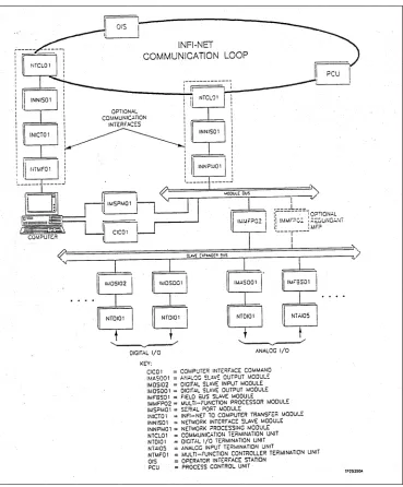
2.1 An Industrial Control System
Figure 2.1: General Layout of the Bailey Infi-90 DCS <Bailey 1990>
2.2 SCADA System Description
A SCADA, or Supervisory Control And Data Acquisition System is a system of computer hardware and software that allows supervision and control of an industrial control system. It communicates with the controllers used in the factory to obtain information about the current state of operation of the plant. It also allows an operator to control the plant by sending control signals back to the controllers. The controllers could be Programmable Logic Controllers (PLC) or a Distributed Control System (DCS).
Another common term used to describe a SCADA system is HMI. This stands for Human Machine Interface. It is used to describe any system that provides an interface between a person and a piece of machinery. The Industrial SCADA System falls into this category. It provides a HMI by displaying process variables to the operator and allowing control of the plant.
2.3 SCADA System Functions
A SCADA System has two basic functions. The first is to display information about the current operating conditions of a piece of factory plant in an informative and graphical interface. The second is to allow supervisory control of the plant by company personnel. Larger commercial systems may also have other features, such as Historical Trending of data to allow the past operation of the plant to be recorded for future reference and for faultfinding. These other features are secondary to the main purpose of the SCADA. Commercial standalone historian packages are available and are commonly used concurrently with the SCADA system. An example of such a package is OSISOFT’s PI.
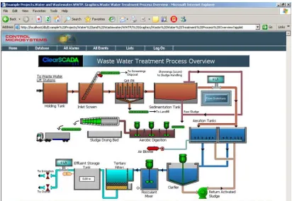
interfaces are developed in specialised Graphical Development Environment software that comprises part of the SCADA software package. This development environment contains standard graphical symbols that can be used on these displays. These symbols are then linked to the appropriate data points in the control system. Any change in value of a data point can be displayed by changing the colour or shape or some other attribute of the symbol. For example, a pump symbol might be red when the pump is tripped and green when the pump is running. In this way a clear picture of the current state of the equipment can be easily obtained. Shown below in Figure 2.2 is an example of a SCADA display.
Figure 2.2: Example SCADA Display
are linked to certain control blocks in the controller. When a value is entered it is passed to the controller and thus alters the process being controlled.
2.4 Commercial SCADA Systems
There are literally hundreds of commercially available SCADA systems on the market. These range from modest packages that provide basic control and display functions for a handful of data tags through to large systems that provide not only these basic functions, but also historical data trending, Tag Database tools and various other information management facilities. These commercial systems can be quite expensive and require extensive training and expertise to allow all the features of the software to be properly configured and utilised.
Commercial SCADA systems are generally not designed for a particular brand or model of controller. The software is generic and covers all types of controllers. To make this generic software work with various manufacturers’ equipment, a software driver is written which uses a controllers unique Applications Programming Interface function calls to provide communications. The required drivers are installed depending on the hardware being used.
2.5 SCADA System Evolution and IP Convergence
To understand the need for an Internet based SCADA system the evolution of SCADA technology must be examined from the point of its inception through to the modern systems we have today. The desired direction for this technology in the future must also be recognised and addressed. These two things give a clear development plan for the next generation of SCADA systems.
The first generation of SCADA systems were generally termed Monolithic (McClanahan 2003). The systems were based around a single Mainframe computer system that performed all computing functions associated with the system. Networks had not yet been developed into a commercially viable technology, so the SCADA systems were standalone systems that were not connected to any other computer (McClanahan 2003). Connection of the controllers to the SCADA master Mainframe was also very limited. It was usually accomplished by using proprietary controllers or adaptors plugged directly into the buses on the CPU backplane. Some limited communication could be established with external systems by utilising communication standards such as RS-232. These were of course simple low-speed serial connections. As can be seen, the first generation of SCADA systems were generally limited in functionality. They also had the drawback of generally tying the consumer to the hardware and software selected and sold by the control system vendor.
Others served as HMIs, allowing control by factory personnel as described in the previous section. Still more nodes existed to provide calculation and database services. By distributing all of these functions between separate machines it was possible to provide more processing power for the system as a whole (McClanahan 2003).
This distribution of computing power also had the advantage of increasing the systems redundancy and reliability (McClanahan 2003). This was achieved by having multiple HMI stations available, so that in the event of a failure of one station the other could be used. This was a feature not available in First Generation SCADA. These early systems had to rely on the failover of a second mainframe that was waiting in hot standby, but was not providing any processing other than to monitor the computer being used.
One final important point to note with Second Generation SCADA systems is the fact that some of the LAN protocols used were of a proprietary nature. The control system manufacturers created their own control system protocols rather than using a common protocol. This allowed them to optimise their LAN for Real-Time traffic. It also had the disadvantage of effectively limiting the devices that could be connected to the LAN to devices produced by the particular vendor that developed the LAN. This was a significant downside of these Second Generation Systems.
The development of the Third Generation SCADA system has led to the present situation. From this point on the future of SCADA systems and indeed Information Technology in general is dominated by the term Convergence. Convergence is used to describe the concept that many different types of Information Technology and Information Services are converging toward a common end. They are being driven to use common protocols so as to allow different systems to integrate and work together in a more efficient and effective way (McClanahan 2003). In particular this refers to the integration of Corporate Networks with SCADA Networks to aid in the prompt transfer of data from the factory to the management and engineering teams and vice versa. With this integration and sharing of common resources comes new problems that must be considered. These include SCADA system security and Quality of Service (QoS) of the real-time data (McClanahan 2003). These are issues that must be addressed in the development of the next generation of SCADA systems.
2.6 Web-Based
Implementations
There are several different Web-based architectures currently on offer for an Internet based SCADA system. The systems are quite different in design and functionality. Each has its own set of advantages and disadvantages and these must be considered with respect to the proposed application. In general, Internet and Web-based SCADA systems have advantages over traditional SCADA systems for reasons of (e-scada.com 2002), (Bentek Systems).
Wide Area Connectivity
Routable connection rather than direct connection Parallel Polling
Redundancy and Hot Standby Large addressing range
Convergence of IT and Automation and Monitoring Networks Standardisation
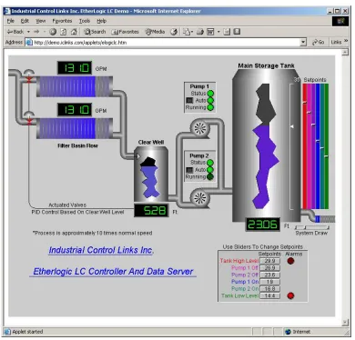
The first system is the PLC with a Web Server embedded directly in the device. This type of device is suitable for small remote standalone systems that do not require a large controller but need remote access via the Internet. The PLC is connected directly to the Internet and has preconfigured web pages stored in the embedded Web Server (Industrial Control Links 2002). These pages are then accessed by the user just as any other web site would be accessed, using a standard web browser such as Internet Explorer, Netscape Navigator or any one of the numerous other browsers available (Industrial Control Links 2002). A PLC such as this is shown in Figure 2.3.
While this type of system is suitable for small projects, it would not be viable for large factories. Another disadvantage is that the graphics are preconfigured and not very flexible when compared with the graphics in a larger traditional SCADA system. An example of the graphics available for the controller of Figure 3 is shown in Figure 2.4. The main advantage of this type of system lies in it’s relatively low cost which allows it to be implemented in small systems.
Figure 2.4: SCADA Display for a PLC with Embedded Web Server <(Industrial Control Links 2002)>
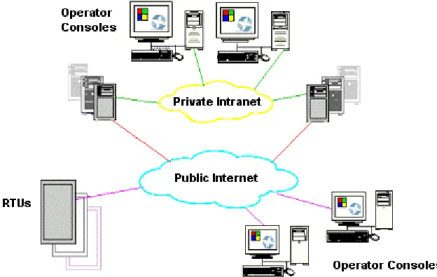
company such as e-scada. This SCADA Service Provider will provide the required data transfer across the Internet between the client’s equipment and their own Web Server. This Web Server does all the data processing and returns the HMI graphics to the user across the web as a Java/Web graphical Interface (e-scada.com 2002). This interface is again accessed using a standard web browser. Figure 2.5 and Figure 2.6 show two different applications based on the SSP system. Figure 2.5 shows remote clients on the Internet accessing the SSP web server in order to control the remote factory plant while Figure 2.6 shows both local and remote clients using the SSP server to access the plant.
Figure 2.5: Remote Access via a SCADA Service Provider <(Control Engineering 2005)>
[image:22.612.177.489.449.647.2]The main advantage of this system is that it removes some of the cost associated with a traditional large scale SCADA system. The need for in house expertise to provide support and maintenance for the system is removed as this is all done by the SCADA Service Provider (e-scada.com 2002).
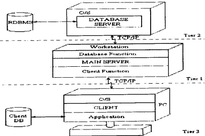
[image:23.612.130.541.265.538.2]Another system is that proposed by Gooi, H.B. and Qiu, B. that is designed for substation control (Qiu, Gooi, Lui & Chan 2002), (Qiu & Gooi 2000). The system is implemented using a three-tier client/server architecture as shown in Figure 2.7.
Figure 2.7: Three Tier Client/Server Architecture of System proposed by Gooi, H.B. and Qui, B.
<(Qiu & Gooi 2000)>
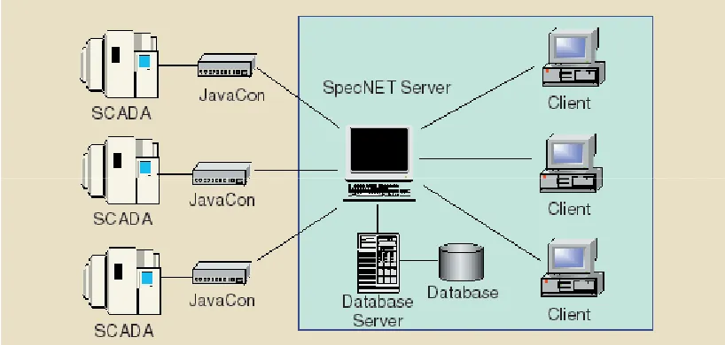
another Java Virtual Machine (Qiu et al. 2002). The SpecNET Server then displays the data from the SpecNET database in Java applets designed to run in a Java enabled web browser. The client side of the web communications is handled through the use of Internet Information Services web server software. The layout of the various components of the system is shown in Figure 2.8.
Figure 2.8: Hardware Layout of System proposed by Gooi, H.B. and Qui, B. <(Qui et al. 2002)>
The system is implemented in Java and uses the Java Database Connectivity (JDBC) drivers to access the database. The main advantage of using Java in this system is that Java is platform independent. This is because the Java bytecode is executed in the Java Virtual Machine at runtime. The end result is that the software can be run across different platforms without modification (Qiu & Gooi 2000).
2.7 Key Issues for an Internet Based SCADA System
of the nature of networks and the Internet in general. These latter problems can be mitigated to some extent but not completely resolved.
The unpredictable transmission latency of networks is one such issue that requires mitigation measures in order for reasonable performance to be expected. The Internet is a shared resource in which many users are simultaneously transmitting data (Luo & Chen 2000). As the number of messages on a network increases the rate of data transfer decreases. This is not desirable in a system designed to transmit real-time data. This issue can be controlled to some extent by appropriate system design, and by implementing techniques such as Traffic Smoothing algorithms (Bello, Kaczynski & Mirabella 2005) and Server Based Scheduling of the network (Nolte, Nolin & Hansson 2005). These techniques are described in Chapter 3. Even with careful design this problem will become more prevalent as the amount of data transmitted increases.
Security is another issue that is of concern to users of Internet based SCADA systems (Qiu et al. 2002), (Qiu & Gooi 2000), (Bentek Systems). The potential exists for unauthorised users to gain access to sensitive information from the SCADA system or indeed gain access to control of the factory plant. The risk of this occurring can be reduced by implementing appropriate security measures such as firewalls, cryptography, digital certificates and public key infrastructure (Qiu et al. 2002). The use of secure hypertext transfer protocol (HTTPS) could also be used to secure transactions across the Internet (Qiu et al. 2002).
Scalability must also be a feature of an Internet based SCADA system. This is the requirement for the system to be capable of handling the transfer of large amounts of data. This particular requirement can be addressed early in the system development by appropriate design techniques.
philosophies. If the system cannot be easily implemented in most situations then it will not be widely accepted. The choice of both system design and programming language are the keys to designing a software system that is platform independent.
One final issue that is a consideration in the design of an Internet based SCADA system is the ease of implementation of the software. This can be measured by the amount of configuration of software such as firewalls that is necessary for the system to operate correctly. A complicated implementation procedure can affect reliability of the system by introducing possible points of human error and therefore system failure. This problem is again overcome by careful system design.
2.8 Chapter
Summary
The main functions of a SCADA system are to display information about the current operating conditions of a piece of factory plant in an informative and graphical interface, and to allow supervisory control of the plant by a factory operator. These functions allow a PLC or DCS or any other variety of controller to be monitored and modified. This makes the safe and efficient operation of modern industrial sites possible.
Chapter 3
Communication over the Internet
3.1 Overview
3.2 The Seven Layer OSI Model
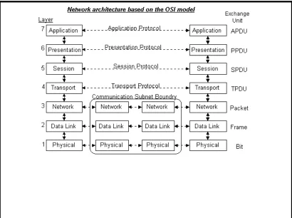
[image:28.612.131.541.305.611.2]In 1983, a branch of the International Standards Organisation called the Open Systems Interconnection Committee developed a layered model that describes how two computer systems could communicate with each other over a network (McClanahan 2003). This model is referred to as the OSI model. It defines seven layers of network functionality that should be addressed by any “open” network. Those seven layers are, from one to seven, the Physical layer, the Data Link layer, the Network layer, the Transport layer, the Session layer, the Presentation layer and the Application layer. This model is shown below in Figure 3.1.
Figure 3.1: The Seven Layer OSI Model <(RAD Data Communications 2003)>
At the top of the stack is the Application Layer. This layer is where the computer applications execute (McClanahan 2003). It also defines the protocols that applications use to exchange data and provides applications the ability to access the services of the other layers (Halar 2003).
The next layer down is the Presentation Layer. This layer is responsible for resolving any environmental differences between the applications that are running on the two different machines (McClanahan 2003). It is this layer that takes care of things such as character code conversion (eg. From ASCII to EBCDIC) and data encryption and decryption. The purpose behind this layer is that the application running in Layer 7 should not have to know about the environment in which the remote target application is running.
Layer 5 is the Session Layer. This layer is responsible for maintaining an ongoing connection between the applications on two separate network nodes (McClanahan 2003). It preserves the packets of a data stream as on ongoing session.
Further down the stack from Layer 5 is Layer 4 or the Transport Layer. It is this layer that ensures that the end-to-end transfer of data across the network is reliable (McClanahan 2003). The transport layer provides a means for lost or corrupted packets to be retransmitted. It also places the packets into the correct order if they arrive out of sequence. Protocols such as TCP and UDP reside in this layer.
Layer 3 is the Network Layer. It describes how packets destined for a node not on the same LAN are to be routed (McClanahan 2003). Logical rather than physical network addresses are used in this layer. The IP protocol exists in this layer.
Ring are implemented. This layer uses the physical address of a node (MAC address) to communicate.
The final layer is the Physical Layer. It is in this layer that the medium connecting the two nodes is defined (McClanahan 2003). This medium may be twisted-pair wire, fibre-optic cable, radio system or any other medium used as a communications connection. It is also in this layer that the electrical characteristics of the signal that passes over the medium are defined.
Communication using this model is done as follows. An application running in Layer 7 on Node 1 wishes to communicate with an application on Node 2. To do this the application passes the packet destined for Node 2 down through each layer of the stack. At each layer the packet is processed and an appropriate header and footer is appended to the packet. At the Physical Layer the packet is transferred to Node 2. Once it reaches Node 2 the procedure is reversed and the packet is passed up through each layer of the stack until it reaches the destination application. At each layer in the stack the packet is analysed and the headers and footers are removed before the packet is passed up to the next layer.
3.3 Sockets and TCP/IP
TCP/IP or Transport Control Protocol/Internet Protocol was developed long before the Seven Layer OSI model was conceived (McClanahan 2003). These protocols (and also the Internet) grew out of an American federal government project in the late 1960s called ARPAnet (Advanced Research Projects Agency). The goal of this project was to link a number of research sites across America with a Wide Area Network (WAN) (McClanahan 2003).
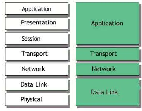
layers 1 and 2 which means that it can run on any type of network infrastructure from Ethernet to token-ring networks to frame-relay circuits and dial-up telephone connections. It is also independent of the layers above it in the stack. This means that any application has the option of implementing TCP/IP as its transport and network protocols. Figure 3.2 shows the relationship between the TCP/IP protocol suite and the seven-layer OSI model.
Figure 3.2: The Seven-Layer OSI Model and TCP/IP Suite <(Tech Target 2005)>
Figure 3.3: A TCP Segment
In the TCP segment, the Source Port identifies the application from which the packet originated. The Destination Port identifies the application on the destination machine that should receive the packet. The Sequence Number identifies each packet in a stream and allows for the reconstruction of this stream on the destination node. These are the important features of the header that ensure proper routing of data between applications. The Acknowledgment Number, Window and Checksum are used to ensure that the transmission is error free.
Figure 3.4: An IP Datagram
The main parts of an IP datagram header with respect to routing functionality are the Source IP Address and the Destination IP Address. These are unique 32 bit addresses that are used to identify a node on a network. IP is a connectionless protocol, which means that there is not a continuous connection between source and destination. Each packet that is sent is treated as an independent unit of data that has no connection to any other packet. The connection between packets is established, as explained previously, by the TCP protocol in the transport layer.
number and IP address of this socket are part of the header of the packet sent to the destination node. In this way the destination node knows which socket to send the response to.
3.4 Distributed Component Object Model (DCOM)
The Distributed Object Component Model is an extension of the Component Object Model (COM). It allows COM components to communicate across a network (Webopedia 2005). COM is a software architecture developed by Microsoft that allows the programmer to develop component-based applications. These applications are built with COM objects, which are discrete components with a unique identity. These components expose interfaces that allow other applications and components to access their features (Webopedia 2005). COM objects are completely language independent and have built-in interprocess communication capability.
DCOM is effectively a method for developing distributed applications. While ordinary COM components can only communicate with other processes on the same machine, DCOM can send and receive data between COM components on different machines across a network (Webopedia 2005). It achieves this by using a Remote Procedure Call approach to send arguments to the server, then receives the resulting data from the server program (Webopedia 2005).
3.5 Hyper Text Transfer Protocol (HTTP)
used to convey information on the World Wide Web. RFC 2616 describes HTTP/1.1, which is the version of HTTP that is most commonly used today.
HTTP is based around a request/response model. An HTTP client sends a request by establishing a TCP connection to a particular port on the server machine (Wikipedia 2005). The default port for HTTP is port 80. The HTTP server that is listening on that port then accepts the request string from the client and sends a response string containing the requested data. HTTP/1.1, unlike previous versions also has a feature called pipelining (Wikipedia 2005). This feature allows a persistent connection to be established between client and server. With previous versions only one request and response were permitted per connection. After the response was received the connection was terminated and any subsequent requests required a new TCP connection. Persistence allows a client to send multiple additional requests and keep the connection alive. This improves data transmission performance as it reduces the TCP connection overhead.
A secure version of HTTP is available called HTTPS (Wikipedia 2005). This protocol uses Secure Sockets Layer technology to authenticate the server for the client. This requires the presence of a Secure Sockets Certificate on the server. HTTPS uses port 443.
3.6 Simple Object Access Protocol (SOAP)
SOAP uses HTTP as its underlying transport protocol. The use of the Hyper Text Transfer Protocol (HTTP) or the secure version HTTPS has the advantage of making communication easier to implement. This is a result of the fact that HTTP uses port 80 to communicate. This is the port used by most web browsers and is therefore left open in firewalls to allow access. The same is true for HTTPS which uses port 443. Individual ports therefore do not have to be configured by systems administrators to allow communication.
3.7 XML Web Services
An XML Web Service is a new technology, implemented in the Microsoft .NET framework, that allows access to software components on different machines across a network using standard web protocols and the XML data format (Thai & Lam 2003). They are similar in function to the DCOM technology described above with the exception that standard web protocols are used rather than the proprietary protocols used in DCOM. HTTP is the primary protocol used and this is implemented by utilising the SOAP protocol.
Web services can be consumed by any application that understands how to parse an XML-formatted data stream transmitted through a HTTP communications channel (Thai & Lam 2003). A Web Services Description Language file is posted on the web server that is hosting the web service. In this file is all the information required to understand how to interact with the web service. It describes an interface’s method calls and gives a list of the input and output parameters for the particular calls. This file can be downloaded by a software developer designing an application to use the service.
Suitable alternatives are programs such as Apache and Microsoft’s Internet Information Services. Figure 3.5 shows the basic components of an XML Web Service.
Figure 3.5: An XML .NET Web Service
<www.west-wind.com/presentations/dotnetwebservices/DotNetWebServicesData.asp>
3.8 Quality of Service of Real-Time Data
required by the real-time data (Lee, Lee & Lee 2005). These techniques can generally only be applied to the local area network as they require all nodes to implement the same technologies in order for the techniques to be effective. This is not possible on the Internet as most of the nodes are beyond the control of any one person.
One method of improving the flow of real-time data over an Ethernet network is to implement a Traffic Smoothing algorithm (Bello, Kaczynski & Mirabella 2005). This technique is used to guarantee a statistical rather than temporal bound on packet delivery times. The theory behind this system is that real-time (RT) packets from a node experience delays due to contention with non-real-time (NRT) packets in the source node and collision with both RT and NRT packets from other nodes.
To solve this issue and ensure that the network loading is at an acceptable level each node on the network is assigned a limit on the amount of data that it can transmit at any one time (Bello, Kaczynski & Mirabella 2005). Each packet to be transmitted from a node is then marked using the Type of Service field in the IP header as either RT or NRT. A piece of software called a Traffic Smoother is then used inserted between the Network and Data Link layers in the OSI model. This traffic smoother gives priority to the RT traffic. The station will transmit RT traffic first, then will transmit its NRT traffic if the amount of RT data sent is below the stations limit. In this way the flow of real-time data is not affected. This technique results in RT traffic having priority over NRT traffic. It also reduces the number of collisions on the network because the flow of NRT traffic has been smoothed.
nodes on the network and tells them when and for how long they can transmit. During each nodes timeslot it transmits first the RT packets and then NRT packets. Using this method no collisions occur as each node is guaranteed to be the only node transmitting at any one time.
It is possible to implement this technique on a network connected to the Internet via an appropriate gateway (Pedreiras et al. 2005). With FFT all nodes on the network must comply with the protocol. The use of a gateway that respects this protocol can allow it to act as a filter for traffic coming into the network. In this way an FFT optimised network can be integrated easily with other networks.
3.9 Communication Method Selected
3.10 Chapter
Summary
Chapter 4
Design Methodology
4.1 Overview
There are a number of key issues that must be addressed in the design of an Internet based SCADA system. Some of these issues can be addressed by the choice of programming language and data communications technique, while others must be dealt with in the consideration of the system design and integration.
4.2 Programming Language Considerations
believed that these languages could be used to implement the desired communications. These languages also have vast amounts of reference information readily available to aid the software developer.
4.3 Programming in C
The C language was created in 1972 by Dennis Ritchie at the Bell Telephone Laboratories (Jones & Aitken 2003). It was originally created to allow the design of the Unix operating system. C is considered to be a procedural language.
C is a powerful and flexible language (Jones & Aitken 2003). It is also modular and fairly portable. These factors have led to C being a very popular language. With C the source code is first compiled in to an object file, then linked to create an executable.
4.4 Programming in C++
C++ is a superset of the C language (Jones & Aitken 2003). It is a high-level object-oriented programming language. Object-object-oriented programming is a fast and efficient way to write software (Snaith 1999). It treats both data and code as a single entity called a class. The advantages of C++ are basically the same as for C with the addition of object-oriented programming.
4.5 Programming in Java
Another object-oriented language is Java. This language was originally conceived by a company called Sun Microsystems as a way to program a device called Star7 that could control household appliances. A Java program is independent of the
a runtime environment called the Java Virtual Machine (JVM) (Keogh 2004). It is also a robust language and is designed for networked computing.
4.6 The
.NET
Framework
The .NET framework is a development framework that provides a programming interface to Windows services and APIs (Thai & Lam 2003). It is a relatively recent development by Microsoft with the version 1.1 being released in April 2003. The .NET framework encompasses 15 languages.
The .NET Framework sits on top of the Windows operating system (Thai & Lam 2003). The most important feature of the framework is its Common Language Runtime (CLR). This can be thought of as similar to the Java Virtual Machine. Intermediate Language Code that is written in a .NET language is compiled at runtime by a Just-in-Time compiler.
The main advantage of the .NET framework is that it allows for easy implementation of Web Services. It was designed from the ground up with networking in mind, with XML Web Services and Distributed Applications development being a couple of its main selling points. Through the use of Web Services it allows distributed
applications to be developed without the problems associated with the older DCOM technology described previously (Thai & Lam 2003).
4.7 Programming Language Selection
network connection implementation. This is a huge benefit to the inexperienced programmer. The Integrated Development Environment used to write the Visual Basic .NET code is Visual Studio .NET 2003 and is shown in Figure 4.1.
Figure 4.1: The Visual Studio .NET IDE
4.8 System Design Alternatives
In order to implement the proposed system there are a number of alternative designs that can be used. These designs each have there strong and weak points with respect to the issues identified and the resources available for program testing.
of the available communication bandwidth. The most efficient way to transfer the control system data is to do it on an exception report basis (Bailey 1990). This means that only the data that has changed since the last update is sent rather than the entire database. This is not easy to implement with the request/response architecture of the Web Service. The client can also send information to the server using the same technique to allow commands to be issued to the control system.
An improvement on this system is one in which two web servers are utilised. One web server is on the client side and one on the server side conceptually. When the client first starts it sends a start message to the server to indicate that it wishes to establish a connection. The server then starts a thread dedicated to that client. When data changes in the database, updates can be sent to the Web Service running on the client. Similarly, control commands can be sent to the Web Service on the server as per the previous design. This system has the advantage that full duplex
communication is established using Web Services, while reducing the use of communication bandwidth through the implementation of an exception reporting system. The disadvantage of this system with respect to this project is that it requires two computers set up as Web Servers to test the design. These resources are not available.
4.10 Chapter
Summary
Chapter 5
System Development and Implementation
5.1 Overall Description
The system design is based around the first proposed design of the previous chapter. A client/server architecture is adopted with a Windows application used as the client of the system. This client polls an XML Web Service running on the server at fixed intervals to obtain the required data from the control system. Both client application and the web service are written in Visual Basic .NET. The machine used as a server is running Windows 2000, therefore Internet Information Services is used as the web server software for the web service to run on. A Microsoft Access database is used as the control system data storage method on the server. This is to allow easy simulation of the system.
5.2 Client-Server
Interoperability
service is a means of allowing an application to access an object on another machine and call its methods as if it were a local object. This function is invisible to the client application. The description of how the web service methods should be called and used is contained in a file known as the Web Services Description Language file. This file can be obtained from the web server hosting the service.
5.3 Server
Program
Function
The web service that comprises the server side of the system has two basic functions. The first is to accept requests from clients on HTTP port 80 and to provide the requested data in XML format. The second function is to connect to the control system database to retrieve the required data for the request. The program listing is contained in Appendix B.
The program begins by creating a namespace (http://Lynchy/JMLScada/PlantData). Part of the namespace contains the name of the server computer, which is in this case called Lynchy. This namespace is a way of creating a hierarchical structure of classes so that the programmer does not have to be concerned that the name of a class that he creates will clash with another class. The web service is then initialized. The code is shown below.
'This code creates an instance of the Web Service.
<System.Web.Services.WebService(Namespace:="http://Lynchy/JMLScada/P lantData/", _
Description:="Live Plant Data")> _
Public Class Plant
Inherits System.Web.Services.WebService #Region " Web Services Designer Code " Public Sub New()
MyBase.New()
'This call is required by the Web Services Designer.
InitializeComponent()
'Required by the Web Services Designer
Private components As System.ComponentModel.IContainer <System.Diagnostics.DebuggerStepThrough()> Private Sub
InitializeComponent()
End Sub
The next piece of code declares a function called GetDataSet which is called by the Web Method of this web service. The GetDataSet function is passed an SQL query as a string by the Web Method that called it. On completion it returns a dataset containing the required data. The first step in this function is to connect to the Microsoft Access database called TestDB which was created for this project to hold the control system data. This connection is set up by the following code.
'Create a connection to the Microsoft Access Database
Dim PlantConnection As New OleDb.OleDbConnection("Jet OLEDB:Global Partial Bulk Ops=2;Jet OLEDB:Registry Path=;Jet OLEDB:Database L" & _
"ocking Mode=1;Jet OLEDB:Database Password=;Data Source=""C:\Documents and Setting" & _
"s\jason\My Documents\Project\TestDB.mdb"";Password=;Jet OLEDB:Engine Type=5;Jet O" & _
"LEDB:Global Bulk
Transactions=1;Provider=""Microsoft.Jet.OLEDB.4.0"";Jet OLEDB:Sys" & _
"tem database=;Jet OLEDB:SFP=False;Extended Properties=;Mode=Share Deny None;Jet " & _
"OLEDB:New Database Password=;Jet OLEDB:Create System Database=False;Jet OLEDB:Do" & _
"n't Copy Locale on Compact=False;Jet OLEDB:Compact Without Replica Repair=False;" & _
"User ID=Admin;Jet OLEDB:Encrypt Database=False")
The SQL query passed to the function is then passed to a database command object and the connection to the database is opened. Following that a data adapter is declared and the SQL command passed to it. A data adapter uses the established connection to the database to execute the SQL query passed to it. This code is shown below.
'Create the command object and pass it the SQL string.
Dim PlantRS As New OleDb.OleDbCommand(strSQL, PlantConnection)
'Create the DataAdapter
Dim PlantDataAdapter As New OleDb.OleDbDataAdapter PlantDataAdapter.SelectCommand = PlantRS
Next a dataset is declared and populated with the results of the data adapter query. A dataset is a memory resident representation of a database that is disconnected from it (Thai & Lam 2003). This dataset can be represented in XML format and is the data returned to the client application that requested it. The file PlantData1.vb in Appendix B is source code auto generated by Visual Studio .NET to set up the structure of the dataset. This structure is described in the file PlantData1.xsd, also in Appendix B. An XSD file is an XML Schema Description file that describes how an XML file is structured. The function finishes by closing the connection to the database and returning the dataset to the web service. The following code shows this step.
'Populate the DataSet and close the connection
Dim PlantDataSet As New DataSet
PlantDataAdapter.Fill(PlantDataSet, "Data") PlantConnection.Close()
'Return the DataSet
Return PlantDataSet End Function
Once the dataset has been passed to the web service, the web service returns the dataset to the client in XML format. The SQL query used in this simple system is a SELECT query that selects all the data from the “Data” table in the specified database. The WebMethod that is called by the client application has the simple structure shown below.
'This Web Method returns the data from the database to the 'client application
<WebMethod()> Public Function GetPlantData() As DataSet Return GetDataSet("SELECT * FROM Data")
End Function
leaving the programmer to concentrate on the functionality of the program rather than the details of the language.
5.4 Client Program Function
[image:50.612.133.538.380.671.2]The client program written to test this system is a simple Windows form. Its basic function is to poll the web service at a fixed interval to obtain the control system data. This interval can be input by the user. The form contains a datagrid and a textbox control. A datagrid is a display control used to display data from a dataset. A textbox control is a control used to accept text. In this case the datagrid displays the data acquired from the web service while the text box accepts a user input for the update time of the data from the web service. The application window is shown in Figure 5.1.
A program listing for the client is contained in Appendix C in the file Main.vb. The client application begins by initialising the form then declaring the controls required on the form. These controls include the datagrid and textbox as well as a label to identify the text box and a timer to implement polling of the web service. After being declared these controls are added to the form.
After this initialisation the form is loaded and a local representation of the class of the web service called lynchy.Plant is declared. This local class that is connected to the web service is called LocalData. The GetPlantData() method of this class is then called once to obtain the initial data values from the Web Service and store them in a dataset called LocalDS. As can be seen from the code below, the application calls this method as if it were calling a method of a class on the local machine. The polling timer is then set with an initial value of one second.
'The following code initialises the form at startup
Private Sub Form1_Load(ByVal sender As System.Object, ByVal e As
System.EventArgs) Handles MyBase.Load
Dim LocalData As lynchy.Plant = New lynchy.Plant Dim LocalDS As DataSet = LocalData.GetPlantData()
DataGrid1.DataSource = LocalDS.Tables("Data").DefaultView Timer1.Interval = 1000
End Sub
'This code calls the Web Service after the timer interval has 'elapsed.
Private Sub Timer1_Elapsed(ByVal sender As System.Object, ByVal
e As System.Timers.ElapsedEventArgs) Handles Timer1.Elapsed If TextBox1.Text > 1000 Then
Timer1.Interval = TextBox1.Text Else : Timer1.Interval = 1000
End If
'This code calls the Web Method on the Web Service
Dim LocalData As lynchy.Plant = New lynchy.Plant Dim LocalDS As DataSet = LocalData.GetPlantData() 'On an error the exception thrown is disabled so that
'the program can retry
On Error GoTo -1
'The DataGrid is updated with the new values
DataGrid1.DataSource = LocalDS.Tables("Data").DefaultView End Sub
The client application continues to poll the web service until it is closed. It should be noted that the reference to the web service is created automatically by parameters entered into a wizard in Visual Studio .NET. The source code for this reference is given in Appendix C in the file Reference.vb. This reference is created from the Web Service Description Language file downloaded from the web server hosting the web service. The PlantData.wsdl file for the web service designed in this project is also included in Appendix C.
5.5 Testing
Process
The testing process involved three stages. The first stage was to test the server by accessing the service through a web browser. The Visual Studio software used for development permits this for a user on the local machine only. This test returns data from the database in XML format and displays the text in the browser window. This stage of testing allowed simple bugs in the server software to be worked out before more complicated interactions with the client application compounded any errors.
was conducted by starting the client application, then changing values in the database using Microsoft Access. These changes were seen in the client application.
The final stage involved testing the complete system across a network. The test was conducted as before with changes made to the database using Microsoft Access. The client application was run on a Windows 98 machine initially, then later a Windows XP machine was used. Although some problems were encountered during the tests, these were resolved and effective communication was established between the client application and the web service.
5.6 Problems
Encountered
Two noteworthy problems were encountered during the testing and development process. These issues were both resolved, though the second issue proved to be quite difficult to find a solution for.
The first problem was encountered during the second stage of testing. The client application was found to hang occasionally with an error message given that stated that an error had occurred. No description of the error was given. This problem was found to be a result of insufficient error handling for the case that communication between the client and server failed. Code was implemented that forced the system to retry until a connection was made. This fixed the problem of the software stalls.
.NET Framework. Neither of these revealed any answers. It was eventually decided to try the software on a later model machine capable of running Windows XP. This trial proved successful with no modification of the original software.
The solution to the issue caused by the failure of the software to run on the Windows 98 machine was not resolved. The same version of the .NET framework was used on both machines and all documentation that could be found indicated that the .NET framework was suitable to run on Windows 98.
5.7 Chapter
Summary
Chapter 6
Conclusions and Recommendations for Future Work
6.1 Achievement of Objectives
This project sought to design the communications backbone of an Internet based SCADA system for use in transferring real-time data from industrial controllers to clients across a network. This system was developed and proved to meet the requirements of a flexible and scalable system suitable for widespread implementation.
Each of the objectives defined in Chapter 1 have been addressed. Comprehensive research was conducted into SCADA systems to determine the key functionalities required for such a system. These functions were identified with respect to their impact on the requirements of the system and were considered in its design.
Different methods of communicating data across the Internet were examined in Chapter 3. The OSI model for open communication networks was presented. This was used to explain the purpose of different protocols in a communication system. A comparison of older technologies with newer ones was also conducted to identify how older networking issues had been resolved and to identify the perceived benefits of these new technologies. An XML Web Service was chosen as the most suitable alternative.
The system was then designed and implemented. The system designed allowed live data in a database to be transferred to a client across a network. This was tested by simulation using Microsoft Access to change values in the database.
The Internet based SCADA system designed provides a flexible and scalable solution to the problem of transferring data from an industrial control system using open Internet protocols. It has the ability to be modified quite easily to solve some of the more difficult issues that still require resolution. These are issues such as security and Quality of Service of the real-time data.
6.2 Future
Work
This project has covered only a small portion of the design of a fully functional Internet based SCADA system. There are several areas where future work should be conducted to improve the functionality of the system. Several of these areas have been identified in previous chapters.
The implementation of a Quality of Service system to improve the flow of real-time traffic across a network that is shared with non-real-time traffic is also an area that should be researched further. Some systems were briefly examined in this project but their implementation was beyond the scope of the project. These systems will improve the functionality of Web-based SCADA immensely and help increase its performance.
The implementation of ASP.NET web pages that can access the web service developed here would also be beneficial. By using these web pages to access the data rather than a dedicated client application, the SCADA graphics could be viewed in a standard web browser.
References
Bailey, 1990, Bailey Infi-90 Open – An Overview
Bailey, 1994, Bailey semAPI Manual
Bello, LL, Kaczynski, GA & Mirabella, O 2005, ‘Improving the Real-Time Behaviour of Ethernet Networks Using Traffic Smoothing’, IEEE Transactions on Industrial Informatics, Vol. 1, No. 3, August.
Bentek Systems, (n.d.), Internet and Web-based SCADA, viewed on 15 October 2005, <www.scadalink.com/technotesIP.htm>
e-scada.com, 2002, viewed on 15 October 2005, <www.e-scada.com/why.html>
HowStuffWorks, 2005, How OSI Works, viewed on , <http://computer.howstuffworks.com/osi1.htm>
Industrial Control Links, 2002, viewed on 15 October 2005. <www.iclinks.com>
Jones, BL & Aitken, P 2003, Teach Yourself C in 21 Days, 6th edn., Sams Publishing, USA.
Keogh, J, 2004, Java Demystified, McGraw-Hill, Emeryville, California.
Lee, KC, Lee, S & Lee, MH 2005, ‘QoS-Based Remote Control of Networked Control Systems Via Profibus Token Passing Protocol’, IEEE Transactions of Industrial Informatics, Vol. 1, No. 3, August.
Luo, RC & Chen, TM 2000, ‘Development of a Multibehaviour-Based Mobile Robot for Remote Supervisory Control Through the Internet’, IEEE/ASME Transactions on Mechatronics, Vol. 5, No. 4, December.
Makitron, 2005, (n.d.), viewed on 15 October 2005, <www.makitron.com/tutorial>
Nolte, T, Nolin, M & Hansson, HA 2005, ‘Real-Time Server-Based Communication With CAN’, IEEE Transactions of Industrial Informatics, Vol. 1, No. 3, August.
Pedreiras, P, Gai, P, Almeida, L & Buttazzo, GC 2005, ‘FTT-Ethernet: A Flexible Real-Time Communication Protocol That Supports Dynamic QoS Management on Ethernet-Based Systems’, IEEE Transactions of Industrial Informatics, Vol. 1, No. 3, August.
Qiu, B & Gooi, HB 2000, ‘Web-Based SCADA Display Systems (WSDS) for Access via Internet’, IEEE Transactions on Power Systems, Vol. 15, No. 2, May.
Qiu, B, Hoay, BG, Yilu, L & Eng KC 2002, ‘Internet-Based SCADA Display System’, IEEE Computer Applications in Power, January.
RAD Data Communications, 2003, viewed on 15 October 2005, The Seven Layers Model, <http://www.rad2.com/networks/1994/osi/layers.htm>
Snaith, P 1999, The Complete Idiots Guide to C++, Que Corporation, USA.
Thai, T & Lam, HQ 2003, .NET Framework Essentials, 3rd edn., O’Reilly & Associates, Sebastopol, California.
Tech Target, 2004, viewed on 15 October 2005, <http://whatis.techtarget.com>
Webopedia, 2005, viewed on 15 October 2005, <www.webopedia.com/TERM/D/DCOM.html>
Webopedia, 2005, viewed on 15 October 2005, <www.webopedia.com/TERM/C/Component_Object_Model.html>
Webopedia, 2005, viewed on 15 October 2005, <www.webopedia.com/R/RPC.html>
<www.west-wind.com/presentations/dotnetwebservices/DotNetWebServicesData.asp>, viewed on 18 August 2005.
Wikipedia, 2005, viewed on 15 October 2005, HyperText Transfer Protocol, <http://en.wikipedia.org/wiki/HTTP>
Appendix A
University of Southern Queensland
FACULTY OF ENGINEERING AND SURVEYING
ENG4111/4112 Research Project
PROJECT SPECIFICATION
FOR: Jason Michael Lynch
TOPIC: AN INTERNET BASED SCADA SYSTEM SUPERVISOR: Dr Peng (Paul) Wen
PROJECT AIM: To design a Supervisory Control And Data Acquisition system that enables a piece of plant to be remotely monitored and controlled via the Internet.
PROGRAMME: Issue A, 21 March 2005
1. Research existing SCADA systems to determine their key components and functions.
2. Investigate current Web-based implementations of SCADA systems.
3. Investigate different methods of communicating data across the Internet.
4. Design a system to allow a local server connected to a PLC to communicate data to a remote server across the Internet.
5. Implement and test the system by simulation.
As time permits:
6. Test the system under real conditions with PLC hardware.
AGREED:
____________________ (Student) ____________________ (Supervisor)
Appendix B
PlantData.asmx.vb
Imports System
Imports System.Data
Imports System.Data.OleDb
Imports System.Web.Services
'This code creates an instance of the Web Service.
<System.Web.Services.WebService(Namespace:="http://Lynchy/JMLScada/P lantData/", _
Description:="Live Plant Data")> _
Public Class Plant
Inherits System.Web.Services.WebService #Region " Web Services Designer Code " Public Sub New()
MyBase.New()
'This call is required by the Web Services Designer.
InitializeComponent()
End Sub
'Required by the Web Services Designer
Private components As System.ComponentModel.IContainer <System.Diagnostics.DebuggerStepThrough()> Private Sub
InitializeComponent()
End Sub
Protected Overloads Overrides Sub Dispose(ByVal disposing As Boolean)
If disposing Then
If Not (components Is Nothing) Then
components.Dispose() End If
End If
MyBase.Dispose(disposing) End Sub
#End Region
'This function retrieves the data from the database and returns it 'as a dataset.
Private Function GetDataSet(ByVal strSQL As String) As DataSet 'Create a connection to the Microsoft Access Database
Dim PlantConnection As New OleDb.OleDbConnection("Jet OLEDB:Global Partial Bulk Ops=2;Jet OLEDB:Registry Path=;Jet OLEDB:Database L" & _
"ocking Mode=1;Jet OLEDB:Database Password=;Data Source=""C:\Documents and Setting" & _
"LEDB:Global Bulk
Transactions=1;Provider=""Microsoft.Jet.OLEDB.4.0"";Jet OLEDB:Sys" & _
"tem database=;Jet OLEDB:SFP=False;Extended Properties=;Mode=Share Deny None;Jet " & _
"OLEDB:New Database Password=;Jet OLEDB:Create System Database=False;Jet OLEDB:Do" & _
"n't Copy Locale on Compact=False;Jet OLEDB:Compact Without Replica Repair=False;" & _
"User ID=Admin;Jet OLEDB:Encrypt Database=False")
'Create the command object and pass it the SQL string.
Dim PlantRS As New OleDb.OleDbCommand(strSQL, PlantConnection)
PlantConnection.Open()
'Create the DataAdapter
Dim PlantDataAdapter As New OleDb.OleDbDataAdapter PlantDataAdapter.SelectCommand = PlantRS
'Populate the DataSet and close the connection
Dim PlantDataSet As New DataSet
PlantDataAdapter.Fill(PlantDataSet, "Data") PlantConnection.Close()
'Return the DataSet
Return PlantDataSet End Function
'This Web Method returns the data from the database to the 'client application
<WebMethod()> Public Function GetPlantData() As DataSet Return GetDataSet("SELECT * FROM Data")
PlantData1.vb
'---
' <autogenerated>
' This code was generated by a tool. ' Runtime Version: 1.1.4322.2032 '
' Changes to this file may cause incorrect behavior and will be ' lost if the code is regenerated.
' </autogenerated>
'---
Option Strict Off Option Explicit On Imports System
Imports System.Data
Imports System.Runtime.Serialization
Imports System.Xml
<Serializable(), _
System.ComponentModel.DesignerCategoryAttribute("code"), _ System.Diagnostics.DebuggerStepThrough(), _
System.ComponentModel.ToolboxItem(true)> _
Public Class PlantData1 Inherits DataSet
Private tableData As DataDataTable
Public Sub New() MyBase.New Me.InitClass
Dim schemaChangedHandler As
System.ComponentModel.CollectionChangeEventHandler = AddressOf Me.SchemaChanged
AddHandler Me.Tables.CollectionChanged, schemaChangedHandler AddHandler Me.Relations.CollectionChanged,
schemaChangedHandler End Sub
Protected Sub New(ByVal info As SerializationInfo, ByVal context
As StreamingContext) MyBase.New
Dim strSchema As String = CType(info.GetValue("XmlSchema",
GetType(System.String)),String)
If (Not (strSchema) Is Nothing) Then
Dim ds As DataSet = New DataSet
ds.ReadXmlSchema(New XmlTextReader(New
System.IO.StringReader(strSchema)))
If (Not (ds.Tables("Data")) Is Nothing) Then
Me.Tables.Add(New DataDataTable(ds.Tables("Data"))) End If
Me.Prefix = ds.Prefix
Me.Namespace = ds.Namespace Me.Locale = ds.Locale
Me.CaseSensitive = ds.CaseSensitive
Me.EnforceConstraints = ds.EnforceConstraints
Me.Merge(ds, false, System.Data.MissingSchemaAction.Add) Me.InitVars
Else
Me.InitClass End If
Me.GetSerializationData(info, context) Dim schemaChangedHandler As
System.ComponentModel.CollectionChangeEventHandler = AddressOf Me.SchemaChanged
AddHandler Me.Tables.CollectionChanged, schemaChangedHandler AddHandler Me.Relations.CollectionChanged,
schemaChangedHandler End Sub
<System.ComponentModel.Browsable(false), _
System.ComponentModel.DesignerSerializationVisibilityAttribute(Syste m.ComponentModel.DesignerSerializationVisibility.Content)> _
Public ReadOnly Property Data As DataDataTable Get
Return Me.tableData End Get
End Property
Public Overrides Function Clone() As DataSet
Dim cln As PlantData1 = CType(MyBase.Clone,PlantData1) cln.InitVars
Return cln End Function
Protected Overrides Function ShouldSerializeTables() As Boolean
Return false
End Function
Protected Overrides Function ShouldSerializeRelations() As Boolean
R