Comparison of Different Technologies for Improving
Commutation Failure Immunity Index for LCC HVDC in Weak
AC Systems
J Burr*, S Finney*, C Booth*
*University of Strathclyde, UK, [email protected]
Keywords: HVDC, LCC, VSC, FACTS, CFII
Abstract
Flexible AC Transmission System (FACTS) devices and Voltage Source Converter (VSC) High Voltage Direct Current (HVDC) systems have fast reactive power control capabilities which can be used to increase power system voltage stability. When located near a Line Commutated Converter (LCC) HVDC converter they can be used to support the performance of the LCC HVDC. This paper shows how well VSC HVDC, Static synchronous Compensation (STATCOM) and Static Var Compensators (SVC) are able to support LCC HVDC based on their improvement of the LCC HVDC Commutation Failure Immunity Index (CFII) and presents a comparison of their relative capabilities.
1 Introduction
HVDC is becoming an increasingly popular choice for bulk power transmission. It has distinct benefits over AC transmission, which include direct bi-directional real and reactive power flow control (for VSC systems), increased efficiency and the viability of long distance subsea cables [1]. The two types of HVDC are LCC HVDC, also known as HVDC Classic, and VSC HVDC, also known as HVDC PLUS [2] or HVDC light [3].
LCC HVDC is a mature technology which has been used for over 50 years and still has the highest power rating and efficiency and lowest cost of the two technologies (i.e. LCC and VSC). However, LCC HVDC, which uses thyristor technology switching at line frequency, has the distinct disadvantage of being susceptible to commutation failures caused by disturbances on the AC side of the converter, particularly those disturbances that lead to a voltage depression on the AC system to which the LCC HVDC system is connected. This disadvantage means that the AC system that the LCC HVDC converter is connected to must be sufficiently strong such that faults occurring on the AC system will not cause a significant disturbance to the voltage waveform, resulting in commutation failure, and therefore interrupting the correct operation of the converter.
VSC HVDC is a much more modern technology, having only been commercialised in the last 20 years. While VSC still lags in efficiency and power capacity, its advanced controllability is highly desirable for use in weak AC systems and for off-shore networks. VSC HVDC, using Insulated Gate Bipolar Transistor (IGBT) technology switching at up to 2 kHz, is considerably more controllable than LCC HVDC giving independent control of real and reactive power, within current limits, and therefore has AC voltage support capability.
In a scenario where an LCC HVDC link and a VSC HVDC link terminate in close proximity, there is potential for using the voltage support capability of the VSC HVDC to benefit the LCC HVDC [4]. A potential example of this scenario is the western converter of the 500 MW VSC East-West Link and the southern converter of the 2.2 GW LCC Western Link, both terminating in very close proximity in Connah’s Quay, UK [5],[6].
Another recent advance in power systems voltage support is FACTS devices. FACTS can be used to great effect to improve voltage stability of a power system [7]. This makes FACTS ideally suited to the support of LCC HVDC systems which are connected to relatively weak AC systems. Two common shunt-connected FACTS devices, used to increase voltage stability, are SVC and STATCOM, also known as SVC PLUS [8] or SVC light [9].
SVC systems are made up of combinations of thyristor switched capacitors (TSC) and thyristor switched reactors (TSR). TSC allow fast switching in of capacitor banks which gives coarse step control of reactive power generation. TSR allow constantly variable absorption of reactive power by altering the conduction timing of a fixed reactor. The combination of the TSC and TSR allows fine variation of both leading and lagging reactive power. A disadvantage of SVC systems is the requirement for filtering of harmonics introduced by the switching operations.
northern converter of the Western HVDC Link in Hunterston, UK, where the system is considerably weaker than at the southern converter.
This paper presents a comparison of the voltage support performance of VSC HVDC, SVC and STATCOM connected at a Point of Common Coupling (PCC) at the inverter terminal of an LCC HVDC system. The performance of each technology will be assessed based on its ability to improve the robustness of the LCC HVDC system in terms of withstanding AC voltage disturbances that may otherwise cause commutation failures.
2 AC-DC Interaction
There is significant interaction between AC and DC systems in AC systems incorporating HVDC links. The operation of LCC converters is highly dependent on the stability of the AC voltage waveform. Disturbances which are likely to cause commutation failures include sudden voltage depressions, voltage waveform distortions and phase shifts. Significant disturbances to the AC voltage will affect the DC voltage at the converter terminals which in turn will affect the DC current. Commutation failures occur when current fails to commutate from one phase to the next in the converter bridge. This results in a short circuit across the converter resulting in a very high current.
[image:2.595.308.549.84.240.2]Considering the circuit shown in Figure 1, the thyristors fire in the sequence V1, V2, V3, V4, V5 and finally V6. Each valve (thyristor) conducts for approximately 120° of one cycle with a small overlap while current is commutating between thyristors. The positive side thyristors conduct in an anti-phase fashion when compared with the corresponding negative side thyristors.
Figure 1: 6 pulse thyristor bridge [10].
Figure 2 shows the thyristor current waveforms leading up to a commutation failure. At time 0.1 V1 and V2 are conducting. V1 then commutates to V3, V2 to V4, V3 to V5 and then V4 to V6. V5 should then commutate to V1 but a commutation failure occurs and V5 continues to conduct. At time 0.12, current commutates from V6 to V2. This creates a short circuit across the DC side of the converter as V2 and V5 are of the same phase.
Figure 2: Commutation failure in thyristor bridge currents [10].
Commutation failures occur due to there being insufficient time for the current in a thyristor to drop to zero. This time is termed the extinction angle, . At the rectifier the firing angle,
, is low to produce a positive DC voltage resulting in a high
. However, at the inverter is high to produce a negative DC voltage resulting in a low value of . Commutation failures are more likely to occur at the inverter end of an LCC HVDC system because the extinction angle of the thyristors is considerably lower at the inverter than the rectifier. A thorough analysis of commutation failures is presented in [10],[11].
2.1 System Strength
AC system strength in relation to a connected HVDC system is characterised by short circuit ratio (SCR), as shown in equation (1), which is the ratio of the short circuit level (SCL) at the point of connection to the DC power rating of the HVDC system, Pdc [1]. A further modification, in equation
(2), is to take into account the effect of shunt connected reactive compensation at the HVDC inverter. This gives the Effective SCR through reducing the SCL by the rating of the capacitor and filter banks of the HVDC system, Qcf, which
generally equates to 0.55 pu of the HVDC system rating.
[image:2.595.42.287.499.621.2]
smaller disturbance for a given fault impedance. Therefore, susceptibility to commutation failure should decrease as SCR increases.
2.2 Commutation Failure Immunity Index
The robustness of an LCC HVDC system connected to an AC system of a particular strength can be characterised by its Commutation Failure Immunity Index (CFII). This is determined through simulation of the system by applying a 3-phase to earth fault through an inductive impedance at the inverter AC connection. Inductive faults, rather than resistive or capacitive faults, are the most representative of actual faults and have been shown to be the most severe faults, other than zero impedance short circuits, in relation to risk of causing commutation failures [12]. The CFII is analysed by finding the critical fault level that can be applied at the inverter PCC which is at the limit of causing a commutation failure. CFII is defined in equation (3)[12].
Where Lmin is the lowest inductive impedance fault the
converter can survive. Therefore, the CFII is the critical fault level that does not cause a commutation failure, expressed as a percentage of the HVDC rated power.
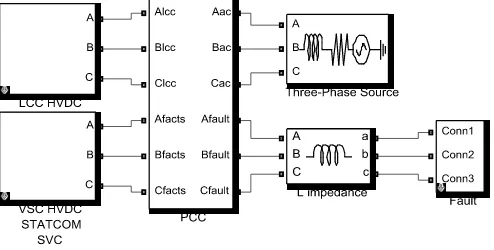
3 System Description and Modelling
[image:3.595.302.554.165.255.2]All modelling and simulation was performed using Matlab Simulink. The overall system is as shown in Figure 3.
Figure 3: CFII study system.
The LCC HVDC system has been modelled using thyristor bridges based on the 1000 MW CIGRE benchmark system [13], as shown in Figure 4. The system has been adapted such that the inverter AC system operates at 1 pu AC voltage for all AC system strengths and power flows. The rectifier end AC system has been maintained as in the original CIGRE system with an SCR of 2.5. The system has also been scaled
[image:3.595.306.558.407.524.2]so that the converters can achieve consistent operating conditions for different levels of power flow. The system operates in constant current control at the rectifier and constant gamma control at the inverter.
Figure 4: LCC HVDC model based on CIGRE Benchmark. The VSC HVDC system has been modelled as a three-phase, controllable, voltage source shunt connected to the PCC through an inductive-resistive impedance, to represent the transformer leakage impedance between the VSC and the grid, as shown in Figure 5. The inductance and resistance were set at 0.2 pu and 0.04 pu, respectively.
Figure 5: VSC/STATCOM modelled as controllable voltage source.
[image:3.595.46.293.514.639.2]has been considered in this study because the AC system at the PCC is the one of interest. Therefore, the remote AC system and converter have not been investigated. The control scheme used for the modelled converter is based on controlling active power flow and AC voltage. It is assumed that DC voltage control of the VSC HVDC link would be performed at the remote converter which has not been modelled. As VSC HVDC and STATCOM are based on similar technology, they have been modelled in the same way; however the STATCOM is limited to zero real power flow. The SVC system has been modelled using thyristor switching of banks of reactive compensation components. The reactive compensation consists of one bank of TSCs rated at 1 pu reactive power rating of the SVC and four banks of TSR each rated at 0.25 pu reactive power rating. One bank of TSR is firing angle-controlled to achieve constantly variable reactance. Harmonic filters of 3rd, 5th and 7th order are
included rated at 0.2 pu, 0.05 pu and 0.05 pu reactive power ratings respectively to provide reactive power and reduce the harmonics introduced by the thyristor switching.
The AC system is represented as an AC source in series with an inductive-resistive impedance that can be varied to implement different system strengths. Throughout the study the nominal voltage of the PCC is maintained at 1 pu by adjusting the magnitude of the voltage of the AC source for different system strengths (i.e. source impedances), and for different power flows.
4 CFII Study and Results
The CFII study was performed by simulating the LCC HVDC system and applying a fault when the system had reached steady state. The simulation was repeated multiple times for different values of fault impedance to find the lowest value of fault impedance that would not cause a commutation failure. This was repeated for system strengths from SCR of 2 to 3 in increments of 0.1 SCR.
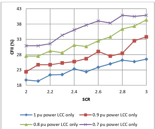
4.1 CFII of LCC HVDC only
[image:4.595.303.555.79.288.2]The CFII of the LCC HVDC system, without any FACTS or VSC HVDC connected was found for reduced levels of power flow from 1 pu to 0.7 pu as shown in Figure 6.
Figure 6: CFII of LCC HVDC only
Reducing power flow increases CFII as it effectively increases the SCR of the AC system. This suggests that in contingency situations where the strength of the inverter end AC system has been reduced, for example by some planned or unplanned generation outage, the power flow of the LCC HVDC could be reduced to improve CFII, which would become a serious concern in an already compromised AC network.
4.2 CFII of LCC HVDC with SVC
SVC has been successfully used to provide voltage control in many AC systems. However, its potential for fast dynamic support of LCC HVDC systems has been tested by finding the CFII of the LCC HVDC system with SVC connected at the PCC.
Figure 7: CFII of LCC HVDC with SVC
18 23 28 33 38 43
2 2.2 2.4 2.6 2.8 3
CF
II
(
%)
SCR
1 pu power LCC only 0.9 pu power LCC only
0.8 pu power LCC only 0.7 pu power LCC only
18 20 22 24 26 28 30
2 2.2 2.4 2.6 2.8 3
CFII
(%)
SCR
1 pu power LCC only 100 MVA SVC
[image:4.595.303.555.532.741.2]Figure 7 shows that CFII is generally slightly improved, but not significantly, with an SVC connected at the PCC. The rating of the SVC doesn’t appear to have a significant effect on the CFII improvement. This seemingly poor performance may be due to the speed at which the SVC reacts to the fault on the system. As both LCC HVDC and SVC use thyristor technology they will have very similar response times. If the LCC system cannot respond fast enough to avoid a commutation failure by adjusting the rectifier and inverter firing angles then the SVC system is unlikely to be able to react much faster to support it significantly. Another potential cause for the apparent non-improvement in performance is that the switching of TSR or TSC banks could cause further unwanted disturbance to the AC voltage waveform due to the sudden large increase/decrease of reactive power. This could be mitigated by ensuring that no large banks of components are switched if a commutation failure is likely, but this effectively reduces the reactive compensation available to support the voltage.
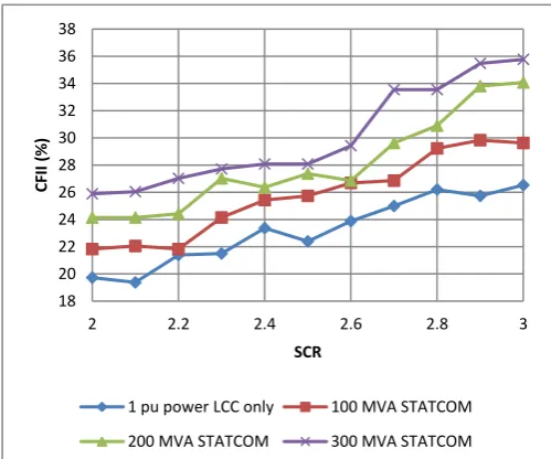
4.3 CFII of LCC HVDC with STATCOM
[image:5.595.304.554.208.417.2]STATCOM provides the same operational purpose as SVC however it has much faster control as it is not limited by thyristor switching at system frequency the way that SVC is. Therefore, the rapid voltage control of STATCOM is more suited to the fast response required to affect CFII as shown in Figure 8.
Figure 8: CFII of LCC HVDC with STATCOM
STATCOM significantly improves the CFII of the LCC HVDC system. As the rating of the STATCOM increases the improvement in CFII also increases. This is due to increased voltage support available from the higher rated reactive compensation.
4.4 CFII of LCC HVDC with VSC HVDC
VSC HVDC has the significant benefit of reactive power control which allows control of AC voltage. It is also able to provide this voltage control very rapidly, in the same way as the STATCOM.
For the purpose of the CFII study the case of VSC HVDC has been performed for the VSC acting as a power source to the AC system and acting as a load on the AC system.
Figure 9: CFII of LCC HVDC with VSC HVDC acting as a source.
Figure 9 shows that VSC acting as a source on the AC system has a slightly negative effect on CFII. This is because the power provided by the VSC system drops during the fault, increasing the power deficit and therefore the AC voltage drop. This results in an effectively reduced SCR. The rating of the VSC system does not significantly change the affect on CFII.
18 20 22 24 26 28 30 32 34 36 38
2 2.2 2.4 2.6 2.8 3
CF
II
(
%)
SCR
1 pu power LCC only 100 MVA STATCOM
200 MVA STATCOM 300 MVA STATCOM
16 18 20 22 24 26 28 30
2 2.2 2.4 2.6 2.8 3
CF
II
(
%)
SCR
1 pu power LCC only 100 MVA VSC source
[image:5.595.43.293.415.623.2]Figure 10: CFII of LCC HVDC with VSC HVDC acting as a load.
Figure 10 shows that CFII is significantly increased with VSC acting as a load. This is because the power being exported from the AC system by the VSC HVDC reduces during the fault, reducing the power deficit and increasing the AC voltage. Increased VSC rating provides increased CFII as the available reactive power compensation is increased and the power being drawn from the AC system is decreased. Considering the significant improvement of CFII for LCC HVDC with reduced power flow, a coordinated control strategy could be implemented between the LCC HVDC and the VSC HVDC. For a reduced AC system strength at the inverter PCC the input power to the AC system could be maintained by a combination of the HVDC systems power flows, assuming the amount of generation/load at the remote converter of each system is flexible. In order to achieve maximum CFII the LCC power flow could be reduced while increasing/decreasing the VSC HVDC power flow depending on whether it is acting as a source or load at the time. This would result in the power flow into the AC system at the PCC being unchanged but the CFII would be increased, which in turn would increase system security.
4.4 Comparison of CFII with Different Technologies
The results of the CFII analysis have been compared to find which has the most influence in improving CFII.
Figure 11: Comparison CFII of LCC HVDC with different technologies.
Figure 11 clearly shows that the thyristor technology of SVC has a much less significant impact than the more rapid controllability of the VSC and STATCOM technology. VSC acting as a source shows a slight decrease in CFII.
STATCOM shows significant increase in CFII. The most significant increases in CFII are achieved by reducing LCC HVDC power flow and by VSC HVDC acting as a load at the PCC. Both scenarios effectively increase SCR and VSC also has voltage support capability which improves CFII further still.
4 Conclusions
This paper has shown that SVC, while being successfully used for voltage control, has no significant contribution to improving CFII in weak AC systems due to its relatively slow response time. STATCOM and VSC acting as a load on the system both achieve significant improvement in increasing the CFII of LCC HVDC systems connected to weak AC systems. It has also been shown that the improvement increases for higher ratings of STATCOM and VSC HVDC. CFII has been shown to increase with reduced LCC HVDC power flow. However, VSC HVDC acting as a source to the AC system reduces CFII due to the loss of power during a fault. These results suggest that a coordinated control strategy could be implemented between LCC HVDC and VSC HVDC to maximise CFII.
Acknowledgements
The authors would like to thank National Grid and the EPRSC for funding this research.
18 23 28 33 38 43 48
2 2.2 2.4 2.6 2.8 3
CFII
(%)
SCR
1 pu power LCC only 100 MVA VSC load
200 MVA VSC load 300 MVA VSC load
16 21 26 31 36 41 46 51
2 2.2 2.4 2.6 2.8 3
CF
II
(
%)
SCR
1 pu power LCC alone 300 MVA SVC
300 MVA STATCOM 300 MVA VSC load
References
[1] Alstom Grid “Connecting to the Future” Alstom Grid, Levallois-Perret Cedex, France, 2010
[2] Friedrich, K., "Modern HVDC PLUS application of VSC in Modular Multilevel Converter topology," Industrial Electronics (ISIE), 2010 IEEE International Symposium on , pp.3807,3810, 4-7 July 2010
[3] Asplund, G., "Application of HVDC Light to power system enhancement," Power Engineering Society Winter Meeting, 2000. IEEE , vol.4, pp.2498,2503 vol.4, 2000
[4] Chunyi Guo; Yi Zhang; Gole, A.M.; Chengyong Zhao, "Analysis of Dual-Infeed HVDC With LCC–HVDC and VSC–HVDC," Power Delivery, IEEE Transactions on ,
vol.27, no.3, pp.1529,1537, July 2012
[5] Egan, J.; O'Rourke, P.; Sellick, R.; Tomlinson, P.; Johnson, B.; Svensson, S., "Overview of the 500MW EirGrid East-West Interconnector, considering System Design and execution-phase issues," Power Engineering Conference (UPEC), 2013 48th International Universities' , pp.1,6, 2-5 Sept. 2013
[6] Achenbach, S.; Barry, V.; Bayfield, C.H.; Coventry, P.F., "Increasing the GB electricity transmission networks' power transfer capability between North and South — The Western HVDC Link," AC and DC Power Transmission (ACDC 2012), 10th IET International Conference on , pp.1,4, 4-5 Dec. 2012
[7] Dixon, J.; Moran, L.; Rodriguez, J.; Domke, R., "Reactive Power Compensation Technologies: State-of-the-Art Review," Proceedings of the IEEE , vol.93, no.12, pp.2144,2164, Dec. 2005
[8]
http://www.energy.siemens.com/hq/en/power-transmission/facts/static-var-compensator-plus/, accessed on 22nd October, 2014
[9] http://new.abb.com/facts/statcom , accessed on 22nd
October, 2014
[10] CIGRE Working Group 14.05 CIGRE. “Commutation Failures Causes and Consequences” Brochure 103, 1996 [11] Thio, C.V.; Davies, J.B.; Kent, K.L., "Commutation
failures in HVDC transmission systems," Power Delivery, IEEE Transactions on , vol.11, no.2, pp.946,957, Apr 1996
[12] Rahimi, E.; Gole, A.M.; Davies, J.B.; Fernando, I.T.; Kent, K.L., "Commutation failure in single- and multi-infeed HVDC systems," AC and DC Power Transmission, 2006. ACDC 2006. The 8th IEE International Conference on , pp.182,186, 28-31 March 2006
[13] CIGRE Working Group 14.02, " The CIGRE HVDC Benchmark Model: A new Proposal with Revised Parameters," Electra, ELT_157_2 , 1994
![Figure 1: 6 pulse thyristor bridge [10].](https://thumb-us.123doks.com/thumbv2/123dok_us/1579608.110575/2.595.42.287.499.621/figure-pulse-thyristor-bridge.webp)