Abstract—High voltage direct current (HVDC) power transmission is becoming increasingly important due to steadily rising need for bulk power delivery and interconnected power transmission and distribution systems. DC grids are vulnerable to dc faults, which lead to a rapid rise in dc fault currents. The dc faults must be cleared within timeframe of milliseconds to avoid collapse of the HVDC system. In the event of primary protection (PP) failure, back-up protection (BP) must be applied to clear the fault. In this paper, a novel algorithm based on a Naïve Bayes classifier is proposed to determine threshold levels and operational time frames for primary and back-up protection in multi-terminal voltage source converter based HVDC (VSC-HVDC). Local voltage and currents are measured to detect and identify the kind of fault. A four terminal HVDC transmission system is developed in PSCAD/EMTDC and is subjected to line-line faults at different locations and time, to assess the designed protection schemes. Results show that relaying algorithm effectively detects the fault and expedite the primary protection operation. On malfunctioning of PP, BP is accelerated in a short delay of 0.2ms. Furthermore, the relaying algorithm provides faster protection compared to techniques available in the literature. The resulting reduced fault clearance time truncates the maximum fault current and inevitably, leads to reduced power ratings required for dc grid equipment.
Index Terms—Back-up protection; Naïve Bayes classifiers; protection system; primary protection; multi-terminal VSC-HVDC
I. INTRODUCTION
NCREASING interest in voltage source converter (VSC) based high voltage dc (HVDC) has been observed. VSC-HVDC technology offers numerous benefits: provides control of
Manuscript submitted on 6 November 2017.
A. Raza, A. Akhtar, M. Jamil, S. O. Gilani and M. N. Khan are with the Department of Robotic and AI, National University of Sciences and Technology, Islamabad 44000, Pakistan (e-mail: [email protected]; [email protected]; [email protected]; [email protected] du.pk; [email protected]).
G. Abbass is with the Electrical Engineering Department, University of Lahore, Lahore 54000, Pakistan (email: [email protected]).
L. Yuchao and X. Dianguo is with the School of Electrical Engineering and Automation, Harbin Institute of Technology, Harbin 150001, China (e-mail: [email protected]; [email protected]).
T. Izhar is with the Electrical Engineering Department, University of Engineering and Technology, Lahore 54000, Pakistan (email: [email protected])
B. W. Williams is with the University of Strathclyde, Glasgow G1 1XW, U.K. (e-mail: [email protected]).
both active and reactive power and, the direction of power can be altered by only reversing the current direction. It enables multi-terminal HVDC (MT-HVDC) system implementation as a constant dc bus can be used, unlike with classic line commutated converters (LCC) [1].
Multi-terminal VSC-HVDC systems offer attributes like: redundancy, flexibility, reliability and security for power transmission [2]. DC grid reliability allows safe operation when adopting appropriate action to avoid dc grid failure during severe conditions [3], viz., a dc grid protection scheme. However, dc grid protection faces the challenge of a rapid increase of the dc fault current. Fast detection and identification by protective relays and quick isolation through dc circuit breakers (DCCB) are the basic requirements of HVDC protection systems. The protection systems (PS) must be efficient to identify and locate the fault during the first few milliseconds of the dc fault period. If the PS does not identify and isolate the faulted section timely, fault currents may rise to destructive levels and damage the HVDC converters and the system dc grid voltage may fall down to unacceptably low values. Thus, PS for dc systems must be faster and more accurate than for ac systems [4].
Selective protection of MT-HVDC systems divides the grid into protection zones. Generally, there are two protection zones in the selective dc protection systems for one portion. In the event of a dc fault, respective dc breakers of a specific zone should operate and isolate the faulty portion, preventing fault current propagation into neighboring protection zones [5]. Thus, before the action of the back-up protection (BP), the primary protection (PP) should handle the fault in its zone. If the primary protection fails to perform its function, the back-up protection must be efficient enough to identify the faulty condition and to react accordingly [6].
Many non-unit protection schemes for MT-HVDC systems have been proposed. In [7] and [8], a current derivative based protection technique is employed. The current rate is limited by dc link inductors. However, dc inductance increases DCCB energy requirements. A protection scheme based on voltage is presented in [9] and [10], but long simulations are required to classify various thresholds. The voltage magnitude based protection technique in [6] uses its derivatives to identify and isolate dc faults. However, the method precision deteriorates with reduced sampling frequency. Mechanical DCCB based protection is proposed in [11] with fault clearing times of
A Protection Scheme for Multi-terminal
VSC-HVDC Transmission Systems
Ali Raza, Amin Akhtar, Mohsin Jamil, Ghulam Abbass, Syed Omer Gillani, Liu Yuchao, Muhammad
Nasir Khan, Tahir Izhar, Xu Dianguo,
Fellow, IEEE
, Barry W. Williams
60ms for primary protection while back-up protection operate with delay of 20ms. The proposed relaying algorithms for dc grids do not suffice high operation speed with selectivity. In [12], the algorithm halts BP action until the fault current reduces to near zero through PP, which results in considerable delay in BP operation. Fast back-up protection based on linear discriminant analysis (LDA) is proposed in [13]-[15] with a fault current limiting time of 3.5ms but not zero current. 1.5ms DCCB operating time is considered which practically not possible because of its high on state losses. Moreover, LDA has a drawback of misclassification and hence, its practical implementation is problematic as LDA fails when the discriminator information is not in the mean but rather in variance, of data. Thus, a protection algorithm with a better statistical technique, Naïve Bayes classifier, is presented in this paper.
A non-unit protection scheme based on current and voltage data is investigated for dc grid to devise primary and back-up protection. The proposed technique collects local voltage and current samples and classifies this according to Naïve Bayes to detect and discriminate forward and backward faults. The sign of di/dt is used to discriminate between the protection zones. The scheme offers fast primary protection in the event of fault in Zone 1 and BP operates with selective overshoot time when primary protection fails.
This paper is organized as: test system configuration and controls are described in section II. The proposed protection algorithm for MT-HVDC systems is presented in section III. Section IV explains the routine to discriminate between protection zones using a Naïve Bayes classifier. Simulation results for the proposed algorithm are presented in section V. Finally, conclusions are drawn in section VI.
3
C B
4
C B
21
L
24
L
43
L
32
L
3 1
L
1
CB
1 3
C B
1 2
C B
34
C B
3 1
C B
32
C B
42
C B
43
C B
24
C B
21
C B
23
C B
2
[image:2.612.47.299.463.583.2]CB
Fig. 1. Single line diagram of meshed VSC-HVDC system.
II. PROPOSED MESHED TEST SYSTEM
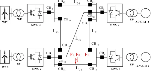
A single line diagram of the proposed four terminal meshed modular multi-level converter (MMC) based HVDC system is shown in the Fig. 1. It consists of meshed (line 32) and ring of lines. Bi-polar connection of transmission lines are realized considering positive and negative dc voltages. Hybrid DCCBs are connected to each end in series with dc inductors (100mH) in each line, to limit the rate of rise of the dc fault current. These inductors do not afford protection against a dc link fault
within a VSC. Lengths for the lines L24, L43, L31, L21 and L32 are: 80km, 80km, 100km, 100km, and 150km, respectively.
A. Control Strategy
Onshore VSC stations (MMC-1 and MMC-2) are set to control the dc voltage through P-Vdc droop control and reactive power control [16]. This setting helps regulate the exchanged reactive power between a converter and the external ac grid plus maintains constant dc link voltage. The remaining converter stations (MMC-3 and MMC-4) are set to P-Vac control mode, which establish constant active power flow across the grid [17] and regulates the ac voltage level at the point of common coupling (PCC).
III. PROTECTION OF MULTI-TERMINAL VSC-HVDCSYSTEMS The main hurdle hampering the implementation of MT-HVDC systems is the non-availability of the protection system. Thus, a complete new technique needs to be established. It is difficult to extinguish the arc in dc systems as the polarity of current remains constant. Available protection algorithms for MT-HVDC are not satisfactory. During a dc grid fault, it is practice to operate ac switchgear to disconnect the whole dc grid: this is not acceptable. The reasons why protecting dc grids is more difficult than ac networks are [9]: 1. Normally, cables are used in VSC-HVDC with high
steady-state-short circuit currents and short rise time. 2. Overcurrent protection is needed for VSCs, being
sensitive to overloads.
3. Switching of dc current is more complicated than the switching of ac.
Viable operation of an MT-HVDC system depends upon its ability to survive during a dc fault, so more investigation is needed on dc fault protection [9], [18]. Following features are recommended for a robust dc grid protection system [9]: 1. Identify the dc fault. Protection systems must be
unresponsive to noise and operate normally. 2. Detect the fault location in system.
3. Operate the relevant DCCBs in a few milliseconds after fault detection in a selective manner.
4. Systems must have adequately fast dc circuit breakers. 5. With primary protection failure, back-up must be
employed.
During and after a dc grid fault, the effect on the connected ac networks must be minimal. Any protection system must be capable of distinguishing between faulty and abnormal conditions of the power system. PS should be insensitive to through faults and capable of handling converter noise.
A. Procedures
Bayes statistical method is used to distinguish between zones 1 and 2.
Fig. 2. Layout of protection zones for dc buses.
The faults are reported as a rise in dc current and a drop in dc voltage level. The inductor at each terminal of the faulty line is employed limits the propagation of a rapid drop in voltage and rise in current. Thus the sign of di/dt describes the direction of any fault current, either forward or reverse.
In protection algorithm, the voltage and current are monitored at relays and compared with threshold values on which protection zones are discriminated and a triggering signal is generated to operate the dc breaker. The sampled data of voltage and current are plotted on a V-I plane. The V-I plane is divided into two zones: Zone 1 (PP) where relay R13 should issue a trip signal to CB13 while in Zone 2 (BP), relay R1 senses the fault and trips DCCBs (CB1, CB13 and CB12), only when acting as back-up. Neighboring relays exchange information through signals TPP-13 and TBP-1 as:
13 1 13 1 13 1
Primary Protection Operate
Secondary Protection Operate
Otherwise
1, 0
0 , 1
0 , 0
PP BP
PP BP
PP BP
T T
T T
T T
[image:3.612.327.555.352.688.2](1)
Fig. 3. Time settings of the primary and back-up protection schemes.
B. Working principle
The proposed topology detects any faults in the designed protection. Protection zone boundaries depend upon the voltage and current measurements. There can be forward and reverse faults. Naturally, primary protection should operate first with an operating time less than the back-up protection. The relationship between the operating times of PP and BP is shown in Fig. 3 [19]. 0.2ms selective overshoot (OS) time is allowed for proper coordination between PP and BP to avoid selectivity problems [19].
The threshold voltage is calculated by substituting the measured current of R13 into = × + [14] and the threshold current is calculated by = + 30% × .
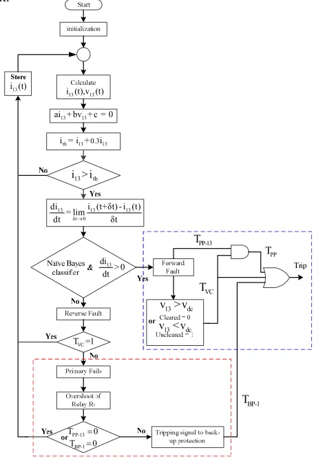
The working flow chart of the proposed protection topology is shown in Fig. 4. The algorithm for primary and back-up protection is as follows:
13 13 13
13 13 13
, and if is poistive
Primary Protection of Zone1
and 0.2 if is negative
Secondary Protection for Zone1
th th
th th
di
v v i i
dt
di
v v i i delay of ms
dt
1)Primary Protection Operation: The blue highlighted dotted block shows the primary protection of R13 in Fig. 4. Primary protection would operate when fault parameters fall within Zone 1. The signal TPP-13 changes from 0 to 1 when PP operates on fault detection within Zone 1. Signal TVC reveals any discrepancy of the dc voltage profile when a DCCB opens as:
13 13
Fault is not cleared 1
Fault is cleared 0
dc VC
dc VC
v v T
v v T
(2)
TPP is the response of an AND gate which has TPP-13 and TVC inputs as shown in Fig. 4. TPP decides on secondary protection operation, as it remains 0 if the PP fails to clear the fault.
Fig. 4. Flow chart of the proposed protection algorithm.
2) Secondary Protection Operation: The red dotted
block represents the back-up protection in Fig. 4. Relay R13 is coordinated with neighboring Zone 2 relay, that is, R1 through
13 13
i (t),v (t)
13 13
ai + bv + c = 0
th 13 0.313
i = i + i
13 th
i > i
13 13 13
δt 0
di i (t+δt) - i (t) = lim
dt δt
13
di > 0 dt
BP-1
T 0
13 dc v > v
13 dc v <v
13
i (t)
VC
T =1
PP-13 T
VC T
PP-13
T 0
BP-1 T
PP
[image:3.612.47.301.400.561.2]signals TPP-13 and TBP-1, respectively. The fault is mitigated by primary protection when both signals (TPP-13 and TBP-1) are 0 otherwise BP of R13 identifies the PP failure. Thus, trip signal TBP-1 = 1 is generated.
The final trip signal issued to the hybrid dc circuit breakers is the product of an OR gate with PP and BP logic signals that is generated by the relays as shown in Fig. 4.
IV. DISCRIMINATION BETWEEN THE PROTECTION ZONES The threshold of the protective zones is achieved by collecting system parameter information (samples); current and voltage at relays R1, R13 and R12, respectively, as shown in Fig. 2, within the fixed time frame. Categorizing the data for best effectiveness is called the data classification and is then used to perform the complex and varied actions. Accurate classification can lead to accurate predictions so, the applied classification method is important. In this paper, border lines are detected by employing the Naïve Bayes classifier. Naive Bayes classification is based on the simplifying assumption that the attribute values are conditionally independent, given the target values [20]. Collected samples are classified into two sets. In other words, the assumption is that for an instantaneous target value, the probability of observing conjunction is the product of the probabilities of individual attributes.
The first set of samples is obtained from Zone 1, primary relay R13 while the second set is obtained from R1, linked with Zone 2. Time frame consideration is crucial to regulate DCCB operation.
A. Naïve Bayes Classifier
Naïve Bayes is conceptually a conditional probability model, which represents a vector U = u(1), u(2)…u(n) of n features having independent variables of a problem instance that need to be classified, with probabilities:
(1) (2) ( )
( , ,... n )
k
P w u u u (3)
for k possible outcomes of vector w, w{0,1} [21]. A probability function is infeasible if ‘n’ is large. So, the conditional probability is damped by using the Bayesian theorem:
( 1) ( 1)
( 1 )
( ) P u w P wr
w u
r
P u
P (4)
whereP u( ) is known as the marginal probability:
( ) ( 1) ( 1) ( 0) ( 0)
P u P u w P wr P u w P wr (5)
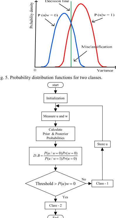
In (5), P u w( 1)is the likelihood, P wr( 1) is posterior probability, and the decision boundary (border or threshold line) is obtained as (6) and is presented in Fig. 5.
( 0) ( 0)
Decision Boundary
( 1) ( 1)
P u w P wr
P u w P wr
(6)
Uncertainty in the Bayesian classifier is calculated in terms of variance to have an indication of class dispersion:
( ) ( 1 ) ( 0 )
P w u P wr u P wr u (7)
[ ] ( 1 ) (1) ( 0 ) (0)
E w u P wr u P wr u
[ ] r( 1 )
E w u P w u (8)
2 2 2
[ ] ( 1 ) (1) ( 0 )(0)
E w u P wr u P wr u
2
[ ] ( 1 )
E w u P wr u (9)
2
var[w u][P wr( 1 u)][P wr 1u] (10)
and the misclassification (Bayes error rate) as in Fig. 5 is calculated from:
(11)
[image:4.612.342.562.61.179.2]where R0 represents the region (overlap) of class 1 in class 2 while R1 is the region of class 2 in class 1. The Naïve Bayes classifier is implemented by the steps in Fig. 6.
Fig. 5. Probability distribution functions for two classes.
start
Initialization
Measure u and w
Calculate Prior & Posterior
Probabilities
Store u
Class - 2
No
Yes
( / 0) ( 0)
.
( / 1) ( 0)
P u w Pr w
D B
P u w Pr u
ThresholdP u w( ) 0
End
Class - 1
Fig. 6. Flow chart for the Naïve Bayes classifier.
Naïve Bayes offers benefits such as: fast to classify the data as it requires only a small data for estimation, insensitive to noise, and handles real and discrete data, unlike LDA [22].
B. Threshold Establishment between the Zones
Low and high impedance (10Ω) faults are applied at various
0 1
( 1) ( 1) ( 0) ( 0)
Error Rate P u w P wr P u w P wr
R R
[image:4.612.319.517.279.651.2]locations on L31 to find the border line equation, for the relays. Faults at a remote distance from the converter; produce attenuated traveling waves compared to faults near B31, thus the different time frames ‘T’. T: time delay as of t0, and t0: time required by the voltage wave to arrive at a converter station after the fault inception instant t0 is zero for F1; conversely, t0 is 1ms for F8 for 100km cable. The samples (dc current and voltage) are monitored at the relays (R12, R13 and R1) with a 10kHz sampling frequency. Projection of the samples, from the relays, on the V-I plane shows the current and voltage values (operating points).
The Naïve Bayes classifier for relay samples for different faults locations, to find threshold line equation, is given by:
( )t 80.5 ( )t 283.5
th R
v i (12)
where, iR(t) represents the measured relay current in kA and vth(t) is the threshold voltage in kV, respectively. As an
example, forward fault (primary protection) and backward fault (back-up protection) samples of F3 are presented in Fig. 7, respectively.
Vdc
Zone 1
Zone 2
0.0 0.5 1.0 1.5
200 300 400
F 3 - PP (1.0, 388)
I dc
F3 - BP(1.08, 376)
±Ø°
x is representing the samples of Zone 1 + is representing the samples of Zone 2
Fig. 7. Threshold (border) line separating the ‘Zone 1’ and ‘Zone 2’ for F3.
During the forward fault, the protection algorithm senses the fault from the first incident wave (first sample), which is located in Zone 1. However, if the protection algorithm does not sense the fault from the first incident wave then the sample falls within Zone 2 (back-up protection). In the next section, simulations demonstrate primary and back-up protection, respectively.
Relay R13 senses the forward fault (FF) F1 after fault inception, as its samples lies in Zone 1. However, R13 detects the FF F8 1ms after fault occurrence because of the limited speed of traveling waves over the long distance. Thus, the trip signal to dc circuit breaker B13 for PP would be triggered within 1ms depending upon the fault location (F1: ~0ms and F8: ~1ms). Conversely, R1 sense the samples linked with Zone 2, that is, backward fault, 2.2ms for F1 and 3.2ms for F8, as hybrid DCCB operating time is 2ms [23], [24].
In the event of the primary protection failure, an enduring time must be maintained for the back-up protection CB to operate to avoid undesirable tripping of remote DCCBs. Thus 0.2ms selective overshoot time is incorporated into the simulations.
V. SIMULATION RESULTS
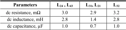
[image:5.612.334.544.548.598.2]Operation of the proposed protection algorithm for MT-HVDC systems is implemented into the four-terminal system of Fig. 1. Fixed active power and ac voltage control is selected for wind farm connected VSCs to extract maximum power. The dc voltage is regulated by applying decentralized voltage droop control with reactive power control on the grid side converters. The CIGRE Bolgona Hybrid DCCB is implemented in PSCAD/EMTDC to verify the effectiveness of the proposed topology. DC inductors are employed to confine the fault current so as to allow effective DCCB operation [25]. The simulated configuration has dc line-line faults (F1, F2, F3…. F8) on L31 to test the operation of primary and back-up protection, in the event of PP relay failure. Employed parameters for Fig. 1 and PI controllers are given in Table I and II, respectively. Electrical characteristics of dc transmission lines (TL) are given in Table III.
Table I. Parameters of the system
System Parameters Values
VSC stations topology MMC
Grid voltage 400 kV
Max. power rating of each VSC station 800 MW VSC stations coupling inductance 1.58 mH Switching frequency 10.0 kHz
dc indictor 100 mH
WF-VSC control P-Vac
GS-VSC control P-Vdc droop-Q Droop constants k1, k2 5, 7 Classification technique Naïve Bayes
Table II.
PI and droop control parameters
PI Parameters Kp Ti
Wind farm ac voltage controller 1.00 1.0000 Active power controller 0.01 0.0400 Reactive power controller 0.00 0.3030 d-axis current controller 0.48 0.0067 q-axis current controller 0.48 0.0067
Table III.
Equivalent parameters of each π sections of all the transmission lines
Parameters L24 , L43 L31, L21 L32
dc resistance, mΩ 3.0 2.9 3.2 dc inductance, mH 2.8 1.4 2.8 dc capacitance, µF 1.0 0.7 1.0
A. Primary Protection
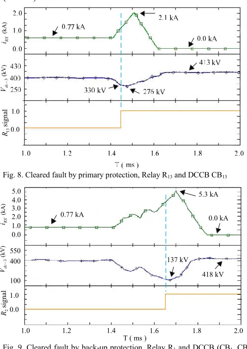
1.15ms and fault current diminished to zero in 2.375ms. Where, 0.375ms used to detect the reflected wave while 2ms consumed to make faulty current zero via hybrid DCCB [23], [24]. Later, TVC becomes 0 to represent that the PP has cleared the fault, because of the voltage rise above the threshold (400kV).
Fig. 8. Cleared fault by primary protection, Relay R13 and DCCB CB13
Fig. 9. Cleared fault by back-up protection, Relay R1 and DCCB (CB1, CB13 and CB12).
B. Back-up Protection
In the event of primary protection failure for F3, adequate operating time for back-up protection CBs should be allowed to avoid selectivity loss between protection zones. Hence, an selective overshoot time is added, 0.2ms, between operation of primary and back-up protection, respectively. Selective OS is minimal than [14] and hence reduce the fault detection time, validity is shown in Fig. 9. Back-up protection trips B12, B13 and B1 to clear the F3 that R13 did not detect. The fault is detected by R1 at 2.575ms (2.375ms + 0.2ms) when the TVC signal state is the consistent ‘0’. Thus, trip signal TBP-1 is issued to DCCBs to isolate the faulty line L31 from the MT-HVDC system. Fault interruption is done according to Fig. 7. Fault is interrupted in 3.575ms and faulted current is reduced to zero in 4.575ms.
Performance of primary and back-up protection validates the proposed protection algorithm for MT-HVDC systems. It reduces fault detection time as fault identification involves the rate of rise of current and tolerable dc voltage level [13], [14].
Naïve Bayes classification discriminates between the zones, and is fast to classify the data as it requires only a few samples to estimate thresholds than LDA.
Table IV.
Comparison of protections schemes Operations based on Naïve Bayes classifier (NBC) and linear discriminate analyses (LDA)
Operating time of DCCB employed in [14]: 1.5ms Operating time of Hybrid DCCB employed for NBC: 2ms
Specifications LDA [14] NBC
Primary Protection
Fault current started to drop 1.5ms 1.000ms Fault current cleared (zero) 4.6ms 2.375ms Back-up
Protection
Fault current started to drop 3.5ms 3.575ms Fault current cleared (zero) 7.8ms 4.575ms
A comparison for protection schemes based on line discriminative analysis and Naïve Bayes classifier is given in Table IV. Comparative analysis shows that primary and back-up protections for NBC are speedy than LDA with accuracy, as simulation results confirmed. Thus, such a protection scheme found its application within MT-HVDC systems.
VI. CONCLUSIONS
Primary and local back-up protection algorithms for MT-HVDC systems was proposed in this paper. Dynamic simulations for a four terminal HVDC system are used to assess primary and back-up protection, when a primary relay fails to detect the fault, respectively. The algorithm realizes a high operational speed by identifying the fault in a primary protection zone and tripped the appropriate dc circuit breaker. The secondary protection scheme quickly detects and isolates the faulty portion during the failure of primary protection with selective overshoot time. This reduces the fault current spike because of the fast operation in clearing faults, compared to the ac protection and recent LDA based dc protection philosophies, as the Naïve Bayes classification is used to find the boundary between primary and back-up protection zones. Thus, MT-HVDC systems are expose to shorter periods of high fault currents and lower voltages, which reduces the ratings of dc grid equipment such as converters and dc breakers. Proposed relaying algorithm is appropriate for MT-HVDC grids where selective protection and DCCBs are employed, as the working of algorithm depends on the current and voltage samples associated with DCCBs operation than the dc system characteristics. Simulation results confirm algorithm performance during both primary and back-up protection. The relaying subsystem is impervious to grid operation changes such as line and converter outages.
REFERENCES
[1] J. Pan, R. Nuqui, et al. “AC grid with embedded VSC-HVDC for secure and efficient power delivery,” IEEE Energy 2030, Atlanta, GA, USA, Nov .2008.
[2] D. Van Hertem and M. Ghandhari, “Multi-terminal VSC HVDC for the European supergrid: Obstacles,” Renew. Sustain. Energy Rev. vol. 14, no. 9, pp. 3156-3163, 2010.
[3] V. Akhmatov, M. Callavik, C. Franck, et al. “Technical guidelines and pre-standardization work for first HVDC grids,” IEEE Trans. Power Del., vol. 9, no. 1, pp. 327–335, Feb. 2013.
0.0 1.0 2.0
(k
A
)
R
X
i
400
3
(kV
)
dc
V
0.0 1.0
2
signal
R
0.77 kA
5.3 kA
0.0 kA
137 kV
418 kV 550
100 4.0
1.0 1.2 1.4 1.6 1.8 2.0
T ( ms ) 3.0
5.0
(k
A
)
RX
i
3
(kV)
dc
V
13
sign
al
[image:6.612.45.293.145.301.2][4] D. Van Hertem, M. Ghandhari, J. Curis, et al. “Protection requirements for a multi-terminal meshed DC grid,” in CigrèIntl. Symp. The Electric Power Syst. of the FutureIntegrating supergrids and microgrids, Bologna, 2011.
[5] P. Anderson, “Power System Protection,” Hoboken, NJ, USA: Wiley, 1998.
[6] W. Leterme, J. Beerten, and D. Van Hertem, “Non-unit protection of HVDC grids with inductive dc cable termination,” IEEE Trans. PowerDel., vol. 31, no. 2, pp. 820-828, 2016.
[7] L. Tang, “Control and protection of multi-terminal dc transmission systems based on voltage-source converters,” Ph.D. dissertation, McGill University, Montreal, QC, Canada, 2003.
[8] J. Yang, J. Fletcher, and J. O'Reilly, “Multiterminal dc wind farm collection grid internal fault analysis and protection design,” IEEE Trans.Power Del., vol. 25, no. 4, pp. 2308–2318, Oct. 2010.
[9] K. De Kerf, K. Srivastava, M. Reza, et al., “Wavelet-based protection strategy for dc faults in multi-terminal VSC HVDC systems,” IET Gen., Transm. Distrib., vol. 5, no. 4, pp. 496–503, Apr. 2011.
[10] R. A. Fisher, “The use of multiple measurements in taxonomic problems,” Ann. Eugen., vol. 5, no. 2, pp. 179-188.
[11] M. Hajian, L. Zhang, and D. Jovcic, “Dc transmission grid with low speed protection using mechanical dc circuit breakers,” IEEE Trans. Power Del., vol. PP, no. 99, pp. 1–1, 2014.
[12] J. Descloux, “Protection contre les courts-circuits des réseaux à courant continu de forte puissance,” Ph.D. dissertation, Université de Grenoble, Grenoble, France, Sep. 2013.
[13] W. Leterme, S. P. Azad, D. V. Hertem, “A Local Backup Protection Algorithm for HVDC grids”, IEEE Trans. Power Del., vol. 31, no. 4, pp. 1767-1775, Aug. 2016.
[14] M. Abedrabbo, D. V. Hertem, “A Primary and Backup Protection Algorithm based on Voltage and Current Measurements for HVDC Grids,” Intl. High Voltage Direct Current Conference, Oct. 2016, pp. 854 -860.
[15] S. P Azad, W. Letermeb, D. V Hertem, “Fast breaker failure backup protection for HVDC grids,” Electric Power Systs. Research, 2016. [16] A. Raza, X. Dianguo, L. Yuchao, S. Xunwen, B. W. Williams and C.
Cecati,"Coordinated Operation and Control of VSC Based Multiterminal High Voltage DC Transmission Systems," IEEE Trans. Sustain. Energy, vol. 7, no. 1, pp. 364-373, Jan. 2016.
[17] J. Liang, T. Jing, O. G. Bellmunt, J. Ekanayake, and N. Jenkins, “Operation and control of multiterminal HVDC transmission for offshore wind farms,” IEEE Trans. Power Del., vol. 26, pp. 2596-2604, Oct. 2011.
[18] Naidoo, D., Ijumba, N.M.: ‘HVDC line protection for the proposed future HVDC systems’. Int. Conf. on Power System Technology – POWERCON, Nov. 2004, pp. 1327–1332.
[19] Y. G. Paithankar , S. R. Bhide, “Fundamentals of Power System Protection ,” Prentice-Hall, India, 2003.
[20] R. M. Stefan, “Comparison of Data Classification Methods”, Procdia Economics and Finance, Vol. 3, pp. 420-425, 2012.
[21] Murty, M. Narashima, et al. “Pattern Recognition: An Algorithmic Approach” Springer, 2011.
[22] T. M. Mitchell, “Machine Learning,” McGrawHill,USA,1997. [23] M. Callavik, A. Blomberg, J. Hafner and B. Jacobson, “The Hybrid
HVDC Breakers:An innovation breakthrough enabling reliable HVDC grids,” ABB grid syst., Zürich, Germany, Tech. paper, Nov. 2012. [24] A. Hassan poor, J. Hafner, B. Jacobson, "Technical assessment of load
commutation switch in hybrid HVDC breaker," in Proc.7th Int. conf. on Power Electron. and ECCE Asia (IPEC-ECCE-ASIA), May 2014, pp.3667-3673.