1-6-2010
Multiplexed capillary electrophoresis system
Edward S. Yeung
Iowa State University
Huang-Tsung Chang
National Taiwan University
Eliza N. Fung
Qingbo Li
Xiandan Lu
Follow this and additional works at:
http://lib.dr.iastate.edu/patents
Part of the
Chemistry Commons
This Patent is brought to you for free and open access by the Iowa State University Research Foundation, Inc. at Iowa State University Digital Repository. It has been accepted for inclusion in Iowa State University Patents by an authorized administrator of Iowa State University Digital Repository. For more information, please [email protected].
Recommended Citation
Yeung, Edward S.; Chang, Huang-Tsung; Fung, Eliza N.; Li, Qingbo; and Lu, Xiandan, "Multiplexed capillary electrophoresis system" (2010).Iowa State University Patents. 68.
Abstract
The use of capillary electrophoresis (CE) has greatly improved DNA sequencing rates compared to
conventional slab gel electrophoresis. Part of the improvement in speed, however, has been offset by the loss
of the ability (inherent in slab gels) to accommodate multiple lanes in a single run. Highly multiplexed
capillary electrophoresis, by making possible hundreds or even thousands of parallel sequencing runs,
represents an attractive approach to overcoming the current throughput limitations of existing DNA
sequencing instrumentation.
Keywords
Ames Laboratory
Note: Within nine months of the publication of the mention of the grant of the European patent in the European Patent
09 014
B1
&
(11)EP 1 109 014 B1
(12)
EUROPEAN PATENT SPECIFICATION
(45) Date of publication and mention of the grant of the patent:
06.01.2010 Bulletin 2010/01
(21) Application number: 01200771.2
(22) Date of filing: 16.05.1996
(51) Int Cl.:
G01N 27/447(2006.01)
(54) Multiplexed capillary electrophoresis system
Multiplexvorrichtung für Kapillarelektroforese
Système d’électrophorèse capillaire multiplexe
(84) Designated Contracting States:
DE FR GB
(30) Priority: 19.05.1995 US 444565
(43) Date of publication of application:
20.06.2001 Bulletin 2001/25
(60) Divisional application:
06006746.9 / 1 669 752 06075848.9
06077079.9 / 1 760 462 07075526.9 / 1 835 281 07075527.7 / 1 837 647
(62) Document number(s) of the earlier application(s) in accordance with Art. 76 EPC:
96921215.8 / 0 830 593
(73) Proprietor: Iowa State University
Research Foundation, Inc. Ames, IA 50011-2131 (US)
(72) Inventors:
• Yeung, Edward S. Ames,
Iowa 50014 (US) • Chang, Huan-Tsung,
Dept. of Chem. Nat. Taiwan Univ Taipei (TW)
• Fung, Eliza N. Westfield, NJ 07090 (US) • Li, Qingbo
State College, PA 16801 (US) • Lu, Xiandan
Malden, MA 02148 (US)
(74) Representative: Beresford, Keith Denis Lewis et al
Beresford & Co. 16 High Holborn London
WC1V 6BX (GB)
(56) References cited:
EP-A- 0 294 996 EP-A- 0 330 120 EP-A- 0 619 483 WO-A-94/29712 DE-A- 4 313 367 US-A- 5 192 412 US-A- 5 277 780 US-A- 5 290 419 US-A- 5 324 401
5 10 15 20 25 30 35 40 45 50 55 Description
Background of the Invention
[0001] The use of capillary electrophoresis (CE) has greatly improved DNA sequencing rates compared to conventional slab gel electrophoresis. Part of the improvement in speed, however, has been offset by the loss of the ability (inherent in slab gels) to accommodate multiple lanes in a single run. Highly multiplexed capillary electrophoresis, by making possible hundreds or even thousands of parallel sequencing runs, represents an attractive approach to overcoming the current throughput limitations of existing DNA sequencing instrumentation.
[0002] Excitation and Detection Geometry. Various excitation and detection systems have been developed to accom-modate parallel arrays in capillary electrophoresis. Laser-induced fluorescence (LIF) detection has been the major method employed in the automation of DNA sequencing. The incident laser beam and the collected fluorescence light are typically perpendicular to each other in order to reduce background noise due to light scattering. On-column excitation and detection are generally performed from above the parallel array through transparent windows formed in the capillaries. For example, in one system a beam expander and a cylindrical lens are used to distribute the laser light into a thin line that intersects the axes of the capillaries, which are mounted in a grooved block so as to reduce cross-talk (K. Ueno et al., Anal. Chem., 66, 1424 (1994)). Although a low detection limit and uniform distribution of excitation intensities can be achieved with this system, a long laser line compared to the array width has to be used due to the Gaussian intensity distribution. Thus, half of the laser light in the array region is wasted due to the longer laser line and the presence of the spacer grooves. Cross-talk, though manageable, is still in the range of 10% of the observed signal.
[0003] On-column detection has also been carried out using axial-beam laser-induced fluorescence detection by inserting optical fibers into an end of each separation capillary (J. A. Taylor et al., Anal. Chem., 65, 956 (1993)). However, the intrusion of optical fibers into the separation capillaries affects the electroosmotic flow and increases the possibility for contamination and clogging. Furthermore, the detection limit is higher.
[0004] A type of side-entry excitation in a single capillary system has also been reported (R. N. Zare et al., U.S. Pat. No. 4,675,300 (1987)). In that system, an optical fiber is used to deliver coherent light to a translucent portion of a capillary, and fluorescence is detected through the translucent portion using a second optical fiber positioned perpen-dicular to the first optical fiber. This method suffers from excess stray light contamination and lower collimation efficiency.
[0005] Increased laser power is generally advantageous in providing a larger analyte signal. However, fluorophores are easily bleached, i.e., their fluorescing characteristic is destroyed by the laser beam, even at the milliwatt level, negating any increase in excitation intensity. Thus an LIF geometry that produces high resolution analyte signals while using a lower power laser (i.e., less than 50 mW) would represent a needed improvement in the art.
[0006] Detection Methods and Devices. Highly multiplexed CE imposes great demands on the detection system. For example, in one approach, a two-color confocal fluorescence scanner is employed for 25 capillaries (X. C. Huang et al., Anal. Chem., 64, 967 (1992)). A mechanical stage is used to translate the capillary array across the optical region. Since data acquisition is sequential and not truly parallel, its use for hundreds of capillaries is limited. To be compatible with the high speed provided by CE and the high throughput of a large capillary array, a fast, sensitive, image array detector is required.
[0007] Recently, charge-coupled devices (CCDs) have been used as two-dimensional (n x m) image array detectors to pursue high-speed, high-throughput DNA sequencing. For example, a multiple sheath-flow apparatus and four-color detection system are used by S. Takahashi et al. (Anal, Chem., 66, 1021 (1994)). Two laser beams are combined into one to cross the flow streams in an array of 20 capillaries in a line for excitation, and a CCD is used for simultaneous detection perpendicular to the excitation beam. Superior stray-light rejection can be achieved with this system: However, many challenges remain in scaling up from 20 to hundreds or thousands of capillaries. Misalignment of individual sheath flows, turbulence in the flow paths, improper matching of the laser beam waist over a long distance with the core diameters containing the eluted fragments, and the possible need to incorporate an extra space between the capillaries to accom-modate the sheath flow are just a few of the problems associated with scale-up. Moreover, CCD detectors make major data analysis and storage demands on a system. CCDs read one array row at a time, and the time spent reading any particular row cannot be lengthened or shortened as desired in response to the amount of information in that row. A two-dimensional image array detection system that allowed random addressing and variable exposure times would significantly reduce data storage and analysis demands, and save considerable amounts of time as well.
[0008] A prior art capillary array is described in DE 4313367.
Summary of the Invention
5
10
15
20
25
30
35
40
45
50
55
Brief Description of the Figures
[0010]
Figure 1 is a schematic diagram of a side entry excitation geometry for a multiplexed capillary electrophoresis system. Figure 2 shows a transparent portion of the annular wall of a capillary extending completely around the capillary. Figure 3 shows optical coupling of a transparent path to a location external to the capillary array.
Figure 4 shows optical coupling of pixels in an image array detector with the interior portion and side walls of a capillary in an array of substantially adjacent coplanar parallel capillaries having a pixel to capillary ratio of 2:1. Figure 5 is an overhead view of the 2:1 optical coupling arrangement shown in Figure 4.
Figure 6 shows an overhead view of an alternative optical coupling arrangement wherein the pixel to capillary ratio within the array of substantially adjacent coplanar parallel capillaries is 3:1.
Figure 7 is a cross-sectional view of a 2:1 optical coupling arrangement with an imaging lens interposed between the pixels and the capillaries that are optically coupled to the pixels.
Figure 8 is an overhead view of an alternative optical coupling arrangement wherein the pixel to capillary ratio within an array of substantially adjacent coplanar capillaries is not an integer ratio.
Figure 9 is a schematic diagram of an optical arrangement used to split a line of induced fluorescence in a group of capillaries into two emission channels.
Figure 10 shows base pair resolution of consecutive DNA fragment peaks in different polymer matrices.
Figure 11 is a graphical representation of a comparison of the theoretical plate numbers from the electrophoretic separation of a pBR 322 DNA-Hae III digest stained with ethidium bromide.
Figure 12 shows electrophoretic separation of the mixture of pBR 322 DNA-Hae III, pBR 328 DNA-Bgl I, and pBR 328 DNA-Hinf I digests.
Figure 13 shows electrophoretic separation of PGEM/U DNA fragments from the Sanger DNA sequencing reaction from base 28 to base 108.
Figure 14 shows electrophoretic separation of PGEM/U DNA fragments from the Sanger DNA sequencing reaction from base 420 upwards.
Figure 15 is a schematic diagram of a pressure injection/flush cell for one capillary.
Figure 16A shows CID detection of DNA fragments after a Sanger DNA sequencing reaction without using an exposure-time gradient.
Figure 16B shows CID detection of DNA fragments after a Sanger DNA sequencing reaction using an exposure-time gradient.
Figure 17 is a histogram depicting clustering of peak-height ratios for the four dye labels in a Sanger DNA sequencing experiment.
Figure 18 shows a ratiogram (top, heavy line) used for base calling (i.e., nucleotide sequence identification) in a DNA sequencing analysis.
Detailed Description of the Invention
[0011] The present invention utilizes an integrated approach toward achieving automation, high speed, high accuracy, and low cost in multiplexed capillary electrophoresis DNA sequencing. As used herein, multiplexed capillary electro-phoresis refers to capillary electroelectro-phoresis systems containing at least about 10 capillaries. The various embodiments of the invention are particularly well-suited for use in capillary electrophoresis systems containing at least about 100 capillaries, up to and beyond thousands of capillaries.
[0012] In capillary electrophoresis, a buffer-filled capillary is suspended between two reservoirs filled with buffer. An electric field is applied across the two ends of the capillary. The electrical potential that generates the electric field is in the range of kilovolts. Samples containing one or more components or species are typically introduced at the high potential end and under the influence of the electrical field. Alternatively, the sample is injected using pressure or vacuum. The same sample can be introduced into many capillaries, or a different sample can be introduced into each capillary. Typically, an array of capillaries is held in a guide and the intake ends of the capillaries are dipped into vials that contain samples. After the samples are taken in by the capillaries, the ends of the capillaries are removed from the sample vials and submerged in a buffer which can be in a common container or in separate vials. The samples migrate toward the low potential end. During the migration, components of the sample are electrophoretically separated. After separation, the components are detected by a detector. Detection may be effected while the samples are still in the capillaries or after they have exited the capillaries.
5 10 15 20 25 30 35 40 45 50 55
the band broadening and lead to excessive separation time. Generally, for capillary electrophoresis, the capillaries are about 10 cm to about 5 meters long, and preferably about 20 cm to about 200 cm long. In capillary gel electrophoresis, where typically a polymer separation matrix is used, the more preferred channel length is about 10 cm to about 100 cm long.
[0014] The internal diameter (i.e., bore size) of the capillaries is not critical, although small bore capillaries are more useful in highly multiplexed applications. The invention extends to a wide range of capillary sizes. In general, capillaries can range from about 5-300 micrometers in internal diameter, with about 20-100 micrometers preferred. The length of the capillary can generally range from about 100-3000 mm, with about 300-1000 mm preferred.
[0015] The use of machined channels instead of capillaries has recently been reported (R. A. Mathies et al., Abstract #133, DOE Human Genome Workshop IV, Santa Fe, NM, November 13-17, 1994; J. Balch et al., Abstract #134, DOE Human Genome Workshop IV, Santa Fe, NM, November 13-17, 1994). With conventional technology, however, multiple capillaries are still the more developed format for multiplexed CE runs. However, technologies developed for capillaries, such as those disclosed herein, are readily transferable to machined channels when that technology becomes more developed.
[0016] A suitable capillary is constructed of material that is sturdy and durable so that it can maintain its physical integrity through repeated use under normal conditions for capillary electrophoresis. It is typically constructed of non-conductive material so that high voltages can be applied across the capillary without generating excessive heat. Inorganic materials such as quartz, glass, fused silica, and organic materials such as polytetrafluoroethylene, fluorinated ethylene/ propylene polymers, polyfluoroethylene, aramide, nylon (i.e., polyamide), polyvinyl chloride, polyvinyl fluoride, polysty-rene, polyethylene and the like can be advantageously used to make capillaries.
[0017] Where excitation and/or detection are effected through the capillary wall, a particularly advantageous capillary is one that is constructed of transparent material, as described in more detail below. A transparent capillary that exhibits substantially no fluorescence, i.e., that exhibits fluorescence lower than background level, when exposed to the light used to irradiate a target species is especially useful in cases where excitation is effected through the capillary wall. Such a capillary is available from Polymicro Technologies (Phoenix, AZ). Alternatively, a transparent, non-fluorescing portion can be formed in the wall of an otherwise nontransparent or fluorescing capillary so as to enable excitation and/or detection to be carried out through the capillary wall. For example, fused silica capillaries are generally supplied with a polyimide coating on the outer capillary surface to enhance its resistance to breakage. This coating is known to emit a broad fluorescence when exposed to wavelengths of light under 600 nm. If a through-the-wall excitation scheme is used without first removing this coating, the fluorescence background can mask a weak analyte signal. Thus, a portion of the fluorescing polymer coating can be removed by any convenient method, for example, by boiling in sulfuric acid, by oxidation using a heated probe such as an electrified wire, or by scraping with a knife. In a capillary of approximately 0.1 mm inner diameter or less, a useful transparent portion is about 0.01 mm to about 1.0 mm in width.
[0018] In electrophoresis, the separation buffer is typically selected so that it aids in the solubilization or suspension of the species that are present in the sample. Typically the liquid is an electrolyte which contains both anionic and cationic species. Preferably the electrolyte contains about 0.005-10 moles per liter of ionic species, more preferably about 0.01-0.5 mole per liter of ionic species. Examples of an electrolyte for a typical electrophoresis system include mixtures of water with organic solvents and salts. Representative materials that can be mixed with water to produce appropriate electrolytes includes inorganic salts such as phosphates, bicarbonates and borates; organic acids such as acetic acids, propionic acids, citric acids, chloroacetic acids and their corresponding salts and the like; alkyl amines such as methyl amines; alcohols such as ethanol, methanol, and propanol; polyols such as alkane diols; nitrogen containing solvents such as acetonitrile, pyridine, and the like; ketones such as acetone and methyl ethyl ketone; and alkyl amides such as dimethyl formamide, N-methyl and N-ethyl formamide, and the like. The above ionic and electrolyte species are given for illustrative purposes only. A researcher skilled in the art is able to formulate electrolytes from the above-mentioned species and optionally species such an amino acids, salts, alkalis, etc., to produce suitable support electrolytes for using capillary electrophoresis systems.
[0019] The voltage used for electrophoretic separations is not critical to the invention, and may very widely. Typical voltages are about 500 V-30,000 V, preferably about 1,000-20,000 V.
[0020] Electrophoretic separation can be conducted with or without using a molecular matrix (also referred to herein as a sieving matrix or medium as well as a separation matrix or medium) to effect separation. Where no matrix is used, the technique is commonly termed capillary zone electrophoresis (CZE). Where a matrix is used, the technique is commonly termed capillary gel electrophoresis (CGE). A preferred separation matrix of the invention for use in CGE is a linear polymer solution, such as a poly(ethyleneoxide) solution. However, other separation matrices commonly used in capillary electrophoresis, such as cross-linked polyacrylamide, can also be used in various aspects of the invention. Suitable matrices can be in the form of liquid, gel, or granules.
5 10 15 20 25 30 35 40 45 50 55
thereof. Proteins that are of interest include proteins that are present in blood plasma, which includes albumin, globulin, fibrinogen, blood clotting factors, hormones, and the like. Other interesting proteins that can be separated and detected using capillary electrophoresis systems are interferons, enzymes, growth factors, and the like. Other chemicals that can be separated and detected using the present invention include, but are not limited to pharmaceuticals such as antibiotics, as well as agricultural chemicals such as insecticides and herbicides.
[0022] Of particular interest are the group of macromolecules that are associated with the genetic materials of living organisms. These include nucleic acids and oligonucleotides such as RNA, DNA, their fragments and combinations, chromosomes, genes, as well as fragments and combinations thereof. The invention is especially suited to applications involving DNA diagnostics, such as DNA sequencing, DNA fragment analysis, and DNA fingerprinting. Sequence vari-ations as small as one base or base pair difference between a sample and a control can be detected.
[0023] Excitation and Detection Geometry. It is important to understand what works best when single capillaries are used may not be transferable to a large-scale multiplexed capillary array. A case in point is the standard excitation/ emission geometry for capillary electrophoresis based on tight focusing of the laser beam and efficient collimation by using microscope objectives with large numerical apertures. The Raleigh range of the tightly focused laser beam and the limited field-of-view of a microscope objective simply cannot be extended to monitor more than a few capillaries at a time.
[0024] The present invention provides a multiplexed capillary electrophoresis system "S" having a side-entry excitation geometry. The system is particularly well suited to fluorescence detection of a fluorescent target species in a sample, as will be described further below. Figures 1 and 2 show one embodiment of the invention. Capillaries 1 are arranged in a coplanar, parallel capillary array 2. Preferably, the capillary array 2 contains at least about 100 coplanar, parallel capillaries 1. The annular wall 3 of each capillary 1 has a first transparent portion 4. The transparent portion 4 is transparent to light having a wavelength about equal to a wavelength of a beam of coherent light used to irradiate a target species in a capillary, as is described in more detail below. A transparent medium is one that transmits light with substantially no attendant light scattering. Preferably, the transparent portion 4 is transparent to light having a wavelength of about 200-1500 nm, more preferably about 250-800 nm. In a preferred embodiment, the transparent portion 4 extends com-pletely around the capillary, as shown in Figure 1.
[0025] Together, the transparent portions 4 of the annular walls 3 define a transparent path 5 extending through the capillary array 2 perpendicular to the capillaries 1, as shown in Figure 2. In a particularly preferred embodiment, the transparent path comprises a plane extending through the capillaries, as is the case where the capillaries are fabricated entirely out of transparent material.
[0026] Alternatively, each annular wall 3 can contain a translucent portion defining a translucent path extending through the array 2 perpendicular to the capillaries 1. A translucent medium produces some light scattering when transmitting light. Transparency is preferred over translucency because of greater light throughput and reduced detection S/N.
[0027] It is much easier to maintain a coplanar parallel configuration if the capillaries 1 are substantially adjacent to each other and mounted on a smooth surface, as shown in Figure 1, than if they are physically separated from one another. As used herein, the term "substantially adjacent to each other" means that the coplanar parallel capillaries are closely packed in the array so as to be substantially contiguous along their parallel lengths, leaving essentially no space between adjacent capillaries. Substantially adjacent capillaries can be physically touching each other along all or a portion of their parallel lengths, although slight inconsistencies in capillary wall diameter or other features of the array can prevent them from being in contact along their entire coplanar parallel lengths. The capillary array can contain one or more subsets or subarrays of coplanar, parallel capillaries, with space in between the subsets or subarrays. Preferably, the capillaries in the subsets or subarrays are substantially adjacent to each other.
[0028] Intentional physical separation of capillaries using space or spacers has generally been required in other capillary geometries known in the art, since bringing the capillaries too close together can create excessive interference with fluorescence detection due to increased levels of cross-talk and scattered light. However, cross-talk and light scattering produced by the side-entry excitation geometry of the invention are sufficiently low to eliminate the need for space or spacers between the capillaries 1 as will be discussed below.
[0029] Light scattering and refraction by the annular walls 3 can be further reduced or eliminated by surrounding at least the transparent portion 4 of the capillary array 2 by a medium having a refractive index similar to that characteristic the capillaries 1. Preferably, the transparent portion 4 is surrounded by a liquid medium having a refractive index of about 1.3-1.5, such as water. It is particularly convenient to immerse the entire capillary array 2 in water.
5 10 15 20 25 30 35 40 45 50 55
laser, i.e., a laser emitting light of a single wavelength, is a particularly preferred light source. Alternatively, the wavelength of the laser can be chosen by an interference filter or a glass prism.
[0031] The beam 8 of coherent light can be focused and collimated through a collimating focusing lens 9 interposed between the coherent light source 7 and the capillary array 2. Preferably, the collimated excitation beam 8 has a diameter of less than about 300 Pm, more preferably less than about 75 Pm while traversing the capillaries 1 in the array 2. For an array of about 100 capillaries, the array width is about 1.5 cm, and a lens with a focal length of about 5-30 cm, preferably about 10 cm, is used to focus and collimate the beam 8 such that the beam diameter remains less than about 75 Pm while in the capillaries 1.
[0032] The focused line of the laser may be altered with a beam expander 10 in order to more effectively irradiate a large number of capillaries. The laser beam 8 is expanded perpendicular to the capillary array 2, as shown in Figure 1. This lengthening or "fanning out" of the laser line makes it easier to position the beam so that all capillaries are adequately irradiated. The beam 8 can optionally be altered or redirected, as with a mirror 11, filter 12 or lens 13, prior to contacting the array 2. In Figure 1 two mirrors 11 are used to provide a convenient means for adjusting the direction of the laser beam 8 to become coplanar with the capillary array 2 perpendicular to the capillaries 1. Also shown in Figure 1 are a filter and a lens, although the use of mirrors, filters, lenses, or any combination thereof is optional.
[0033] Conveniently, the disclosed excitation and detection geometry allows the use of relatively low power output lasers (e.g., several mW, typically 0.5 - 50 mW. Because the laser beam 8 sequentially passes through all the capillaries, and because of the low concentration of DNA samples (typically about 10-10 M), very little of the laser beam is wasted.
Furthermore, the geometry is simple and readily scalable up to at least about a thousand capillaries. For example, detection systems are commercially available to image 2048 capillaries. The array width in that case will be 30 cm, which is still compatible with large-format wide-angle lenses. It may no longer be possible to maintain a 75-Pm or narrower beam over this width; however, one can readily use higher laser powers in an unfocused beam to compensate for the mismatch in size between the laser and the capillary cores.
[0034] Figure 3 shows an alternative embodiment of the system "S" wherein the annular walls 3 of the capillaries 1’ have a second transparent portion 14 for optically coupling the transparent path 5 to a location 15 external to the capillary array, such that electromagnetic radiation can travel between the two sites. This embodiment is especially advantageous for fluorescence detection of target species. The second transparent portion 14 is transparent to light having a wavelength about equal to the wavelength of light emitted by a fluorescing target species, designated "E" in Figure 3. Preferably, the second transparent portion 14 is transparent to light having a wavelength of about 200-1,500 nm, more preferably about 250-800 nm. The second transparent portion 14 of each annular wall 3 may conveniently be contiguous with or overlap the first transparent portion 4 of each annular wall 3.
[0035] As shown in Figure 1 at least one capillary 1 may be in fluid communication with a sample 6 so that the sample
6 is drawn into the capillary 1. Preferably, the sample contains a fluorescent target species. The first transparent portion 4 of the annular wall 3 preferably exhibits substantially no fluorescence when exposed to the beam of coherent light 8,
so as to eliminate background fluorescence from the detected fluorescence. More preferably, the first transparent portion
4 exhibits substantially no fluorescence when exposed light having a wavelength of 200-1500 nm, most preferably
250-800 nm. By substantially no fluorescence is meant that the level of fluorescence emitted by the transparent portion, if any, is less than observed background fluorescence. Detection of a target species is preferably effected through the second transparent portion 14. Accordingly, the second transparent portion preferably exhibits substantially no fluores-cence when exposed to light having a wavelength about equal to the wavelength of light emitted by a fluorescing target species, "E". Most preferably, the entire capillary 1’ is constructed from a transparent, non-fluorescing material, such as fused silica. Transparent windows may alternatively be formed in commercial capillaries having an external polyimide coating by removing a portion of the coating, as disclosed above.
[0036] The location 15 external to the capillary array to which the transparent path 5 may be optically coupled is to be broadly understood as any point, line, or planar surface external to the array, including a single pixel, linear array of pixels, or planar array of pixels. Preferably, the location 15 external to the capillary array comprises a planar surface parallel to the capillary array. The location 15 external to the capillary array contains an optical detector 16. A suitable optical detector is capable of detecting fluorescence emission from a target species in a sample in a capillary. Preferably, the optical detector is a two-dimensional image array detector. More preferably, the optical detector is a charge-coupled device (CCD) or a charge-injection device (CID). Most preferably, the optical detector is a CID.
[0037] Where a capillary contains fluorescing target species, fluorescence detection can also be effected by any convenient alternative means, as by using optical fibers. Optical fibers can, for example, be optically coupled to the transparent path 5 axially by inserting one or more optical fiber into a capillary (U.S. Pat. No. 5,324,401).
[0038] Also provided by the invention is a method for detecting fluorescent target species in a sample using a multiplexed capillary electrophoresis system "S" having the side-entry excitation geometry disclosed above. A capillary array 2 of coplanar parallel capillaries 1 as shown in Figure 1 is provided. As shown in Figure 1 each capillary has an intake end
17, an outflow end 18, and an annular wall 3 with a first transparent portion 4 defining a transparent path 5 extending
5 10 15 20 25 30 35 40 45 50 55
introduced into the intake end 17 of at least one capillary 1 such that the sample migrates through the capillary 1 toward the outflow end 18. Preferably, sample introduction is accomplished using pressure injection as disclosed in more detail below. Fluorescence emission is induced from the target species by irradiating it with a beam of coherent light 8 directed along the transparent path 5 (see Figure 2). Preferably, the coherent light has a wavelength of about 200-1500 nm. Fluorescence emission from the target species is detected. In this method, the annular wall 3 of each capillary 1’ in the array 2 has a second transparent portion 14 for optically coupling the transparent path 5 to a location 15 external to the capillary array, as shown in Figure 3, through which the fluorescence emission is detected. For example, fluorescence may be detected by a CCD or a CID positioned at the optically coupled location external to the capillary array. Preferably, the first transparent portion 4 exhibits substantially no fluorescence when exposed to the coherent light used to irradiate the target species. More preferably, the first transparent portion 4 exhibits substantially no fluorescence when exposed to light having a wavelength of 200-1500, most preferably 250-800 nm. In a preferred embodiment of the method, the target species comprises DNA fragments.
[0039] Detection Methods and Devices. The present invention also provides a capillary electrophoresis system having an image array detector optically coupled to at least one of a plurality of coplanar parallel capillaries in a capillary array. The capillaries in the array each have an annular wall containing a transparent portion for optically coupling the interior portion of the capillary to the image array detector. Preferably, the capillaries are substantially adjacent along their parallel lengths. The capillaries may be grouped into subsets or subarrays, as disclosed above. An image array detector detects images of the interior of a capillary using pixels for collecting electromagnetic radiation in the form of photons. A pixel is an image collecting element of the array detector positioned to electronically detect the pictorial elements of interest during the time the pixel is exposed to electromagnetic radiation (e.g., light). A pixel is typically about 26 mi-crometers in diameter and adjacent pixels are typically spaced on a planar surface of the detector about 2-3 mimi-crometers apart. A pixel exposed to electromagnetic radiation produces an electronic signal that is directly proportional to the amount of electromagnetic radiation received during the time it is exposed. This signal is then used for data analysis.
[0040] Specifically, the capillary electrophoresis system of the invention contains an image array detector having linearly aligned pixels located in a plane parallel to the capillary array such that at least one of the capillaries in the capillary array is optically coupled to less than about six of the pixels. The pixels in the linear array may be optically coupled to the interior portion of the capillary or to one of the capillary side walls. Preferably, at least one pixel is optically coupled to a side wall of a capillary proximate to the interior portion. Pixels optically coupled to a side wall have an unfavorable S/N because they are subject to interference from cross-talk and stray light associated with the capillary walls. These pixels can be conveniently disregarded during data collection and analysis when a charge-injected detector is employed as the image array detector, as further described below. In contrast, pixels optically coupled to the interior portion generally have a favorable S/N ratio. A particularly advantageous pixel alignment is one wherein only one pixel is coupled to an interior portion, and the two pixels on either side of the pixel coupled to the interior portion are each coupled to a side wall. In this arrangement, interference from cross-talk and stray light caused by the capillary walls is essentially confined to the pixels coupled to the side walls and does not affect the signal produced by the pixel coupled to the interior portion. This arrangement is preferred over an arrangement optically coupling two or more pixels to the interior portion because it minimizes dark current, which is a function of the number of pixels coupled to the interior portion of a capillary, although such less preferred arrangements are to be understood as also encompassed by the invention for certain embodiments.
[0041] A particularly preferred embodiment of the invention is shown in Figure 4. The capillary electrophoresis system contains a capillary array 2 containing a plurality of coplanar parallel capillaries 1. In this embodiment the transparent portion 20 of the annular wall 3 extends around the capillaries 1, and the capillaries 1 in the array 2 are substantially adjacent. An image array detector 21 having a linear array of pixels 22 located in a plane parallel to the capillary array
2 is optically coupled to the interior portions 23 of the capillaries 1, In this embodiment the ratio of pixels 22 to capillaries 1 is 2:1, and the pixels 22 are positioned such that every second pixel in the linear array is optically coupled to a side wall 24 of a capillary 1. and every pixel in between is coupled to an interior portion 23 of a capillary 1. Figure 5 is an alternative view of the capillary array 2 shown in Figure 4, showing a projection of the optically coupled pixels 22 onto the interior portions 23 and side walls 24, 25 of the substantially adjacent capillaries 1.
[0042] In another embodiment of the invention shown in Figure 6, a group of pixels 26 having a leading pixel 27, a middle group of pixels 28, and a trailing pixel 29, optically coupled to a capillary 1. Specifically, the leading pixel 27 is optically coupled to the first side wall 24 of a capillary 1, the middle group of pixels 28 is optically coupled to an interior portion 23 of a capillary 1, and the trailing pixel 29 is optically coupled to a second side wall 25 of a capillary 1. Preferably, the middle group of pixels comprises two pixels as shown in Figure 6; most preferably, it comprises one pixel, as shown by implication in Figures 4 and 5. In Figure 6, the optically coupled pixels 26 are graphically projected onto the capillaries
1 in the array 2 for ease of illustration. Two pixels 28 are optically coupled to each capillary interior 23. The pixels 27,29
optically coupled to a side wall 24,25 are shared by adjacent capillaries 1.
5 10 15 20 25 30 35 40 45 50 55
Figures 4 and 5; a 3:1 ratio is shown in Figure 6. The coplanar parallel capillaries may be arranged in an array comprising one or more subsets of substantially adjacent coplanar capillaries. In that event, the overall ratio of optically coupled pixels to capillaries for the entire array may be greater than 6:1, although for each subset of substantially adjacent coplanar capillaries the ratio is less than about 6:1. The ratio of optically coupled pixels to capillaries need not be an integer ratio. In that event, the number of pixels optically coupled to each capillary in the array may vary (see Figure 8, described below). Likewise, if the capillaries in the array have variable diameters, the number of pixels optically coupled to each capillary in the array may vary.
[0044] In another preferred embodiment of the invention (Figure 7) an imaging lens 26 is interposed between the capillary array 2 and the image array detector 21 used to optically couple the pixels 22 to the capillaries 1. The alignment in Figure 7 shows a 2:1 ratio of pixels 22 to capillaries 1, wherein every second pixel is optically coupled to a side wall
24 and every pixel in between is coupled to an interior portion 23 of a capillary 1 through the transparent portion 20. The
imaging lens 26 may be any lens capable of transforming an image onto the pixels of the image array detector, such as camera lens, for example a 24 mm wide-angle lens (Canon, Tokyo, Japan, Model FD 24 mm F1.4L, 50 mm diameter) or a condenser lens.
[0045] The image array detector may be a linear image array detector or a two-dimensional image array detector. Preferably it is a two-dimensional image array detector, more preferably a charge transfer device such as a charge-coupled device (CCD) or a charge-injection device (CID). Most preferably, the image array detector is a CID.
[0046] Also provided by the invention is a method for detecting fluorescent target species in a sample using the capillary electrophoresis system described in the preceding paragraphs. According to the method of the invention, a capillary array containing a plurality of coplanar parallel capillaries is provided. The annular wall of each capillary contains a transparent portion for use in optically coupling the interior portion of the capillary to an image array detector. The image array detector may be a linear image array detector or a two-dimensional image array detector. Preferably, the image array detector is a two-dimensional image array detector. More preferably, it is a CCD or a CID, most preferably a CID. The image array detector has linearly aligned pixels located in a plane parallel to the capillary array. The detector is optically coupled to the capillary array such that at least one of the capillaries in the array is optically coupled to less than about six of the linearly aligned pixels. A sample containing a fluorescent target species, preferably a DNA fragment, is introduced into the intake end of the optically coupled capillary such that it migrates through the capillary toward the outflow end. Fluorescence emission from the target species is then induced by irradiating it with a beam of coherent light. Preferably, the irradiating light has a wavelength of about 200-1500 nm, more preferably about 250-800 nm. Fluorescence emission is detected by the image array detector through the transparent portion of the optically coupled capillary using the optically coupled pixels. Preferably, detection is effected at about 20-30° C.
[0047] In a preferred embodiment of the method, the pixels optically coupled to a capillary constitute a group of less than about six pixels, containing a leading pixel, a middle group of pixels, and a trailing pixel (see Figure 6). Prior to the introduction of a sample, the leading pixel is optically coupled to a first side wall of a capillary, the middle group of pixels is optically coupled to the interior portion of a capillary, and the trailing pixel is optically coupled to a second side wall of the capillary. Preferably, the middle group contains two pixels. More preferably, it contains one pixel.
[0048] A further embodiment of the method includes the additional step of selecting one pixel from the middle group of pixels and using that pixel to detect the fluorescence emission from the target species. Where more than one pixel is optically coupled to the interior of a capillary, it is desirable to select only one to analyze and to disregard the others, since the dark current increases with the number of pixels evaluated per capillary, thus increasing background noise. In an array or subarray of substantially adjacent capillaries, ideally only one pixel is optically coupled to each capillary (representing a 2:1 ratio of pixels to capillaries), obviating the need to make a pixel selection. However, in large arrays with many capillaries, it may be of great practical utility to use a higher ratio of pixels to capillaries, to accommodate inconsistancies and variations in capillary packing, annular wall width, and the like. Where higher ratios of pixels to capillaries are used, more than one pixel may be optically coupled to a capillary interior portion. Each of these pixels will produce a signal having an intensity directly proportional to the intensity of light detected. The pixel producing the signal having the greatest intensity when exposed to electromagnetic radiation emanating from the capillary, i.e., the "brightest" pixel, is advantageously selected. Examples of selected pixels 27 are shown by hatched shading in Figure 8. In Figure 8, the optically coupled pixels 23 are graphically projected onto the capillaries in the array for ease of illustration. A hatched pixel represents that pixel optically coupled to a given capillary which produces the greatest signal intensity when the capillary contains a fluorescing material as described below. Data from the hatched pixels is used for sample analysis.
[0049] Selection of the appropriate pixel from those optically coupled to the interior portion of a capillary may conven-iently be made by way of a calibration step. Thus, the method of the invention further includes a calibration step performed prior to introducing the sample. A fluorescing medium, such as a fluorescein solution, preferably a solution containing about 10-8 - 10-5 M fluorescein, or a rhodamine solution, or any convenient fluorescing buffer, is introduced into a capillary.
5 10 15 20 25 30 35 40 45 50 55
portion of the annular wall. The fluorescence emission is detected by each member of the middle group of pixels optically coupled to the interior of the capillary. The intensity of the signal produced by each pixel in the middle group is compared, the pixel producing the signal with the greatest intensity is selected. The fluorescence emitted by a target species detected by the selected pixel is then used to perform data analysis.
[0050] The most preferred image array detector for use in the system and method of the invention is the charge-injection device. Applications of CID are known in the fields of astronomy and atomic spectroscopy (P. Epperson et al., Anal. Chem., 60, 327A (1988)). A CID is a solid-state charge-transfer imaging device (CTD) similar to a CCD, but it has characteristics not shared by CCDs that can be used to great advantage in multiplexed capillary electrophoresis. Where only a single capillary or a small number of capillaries is involved, there is no obvious advantage to using a CID because various photomultiplier tubes, avalanche photodiodes, or CCD cameras are available. However, when a large number of capillaries need to be monitored simultaneously in an array format, the unique features of a CID camera can make a significant difference. Those features include random pixel addressing, flexibility of user programmable architecture (particularly for programming exposure time), large dynamic range, low dark current, anti-blooming imaging, high toler-ance to irradiation, high quantum yield over a wide wavelength range, and non-destructive readout.
[0051] The "random access" or electronic-windowing function unique to CIDs is especially useful. The term "random access" refers to the special features of a CID that allow it to be calibrated or programmed to read only those pixels focused on a particular region of interest, saving enormous data analysis time and storage requirements compared to a CCD, which offers very little flexibility in the pixel readout. For example, a CID can be calibrated to read only one or more pixels focused on a transparent portion of a capillary through which fluorescent emissions from.a target species pass. Thus, the method of the invention further includes using random access programming to select a pixel having the greatest signal intensity from a group of pixels optically coupled to a capillary interior. The sample migration time for the target species is then determined by processing the signal produced by the selected pixel.
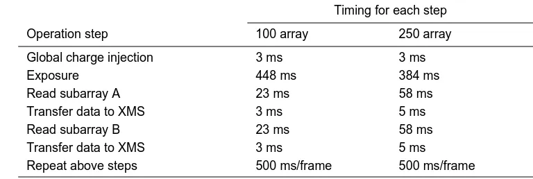
[0052] Although the CID camera is operated at a pixel-read rate slower than a conventional CCD, it can achieve very high sampling rate with high exposure duty cycle and thus high sensitivity. The advantages are even greater when several spatially separated subarrays need to be read, as the space in between the subarrays need not be read in a CID.
[0053] The CID can be further advantageously operated by programming it to utilize different exposure times to detect emissions of variable intensities. Shorter exposure time may be adequate for high intensity emissions, and longer exposure times can be used for lower intensity emissions. For example, a calibration run may be made in a DNA sequencing experiment to determine the approximate migration times of DNA fragments of various lengths. An exposure-time gradient can be then programmed to expose larger, longer running fragments having higher emission intensities for a shorter amount of time than needed for the faster, shorter fragments, thereby improving the signal to noise ratio for the larger DNA fragments while simultaneously reducing the volume of data generated. Thus, the method of the invention further includes using exposure time programming to vary the exposure time for a selected pixel during sample migration substantially inversely with the intensity of fluorescence emission from the target species. The exposure time programming is preferably effected by programming a time exposure gradient, which may be initially determined in a calibration run using DNA fragments of known size and fluorescence intensity, or by programming a feedback loop to automatically vary the exposure time with the fluorescence emission intensity detected by the selected pixel. In a par-ticularly preferred embodiment of the method, both random access programming and exposure time programming are used.
[0054] To overcome any sampling rate limitations of a CID due to the fact that the sampling rate is determined by the charge-injection speed as well as the pixel-read rate, the CID can be operated using an asynchronous scanning mode. In an asynchronous scanning mode, the camera shutter is kept open and the subarray is scanned continuously without waiting between frame readouts to move to the next member of the array. The charge in each pixel is cleared individually during each frame without disturbing the other pixels. The duty cycle, frame rate, and charge-clearing time will vary as a function of the size of the subarray.
[0055] Preferably, the CID is operated at ambient temperature (20-30°). This makes it simpler and more compact to incorporate into an automated DNA sequencing instrument. Because there is no need for a liquid-N2 dewar, the CID focal plane array occupies only a very small space.
5 10 15 20 25 30 35 40 45 50 55
(1987); R. Tomisaki et al., Anal. Sci., 10, 817-820 (1994)), but the use of narrow bandpass filters, which admit light of a given wavelength 10-30 nm, results in low light throughput, leading to a loss of sensitivity. Moreover, uniform incorporation by the polymerase must also be assumed. A four-dye label DNA sequencing experiment utilizing single wavelength excitation and multiwavelength CCD detection utilizing a spectrometer has also been reported (A. E. Karger et al., Nucl. Acids Res., 19, 4955-4962 (1991)), but low light throughput is a major drawback of this scheme as well.
[0057] Accordingly, the capillary electrophoresis system preferably utilizes only one excitation wavelength and that utilizes two long-pass filters, described below, to split the fluorescence emission into first and second emission channels. As a result of the splitting, the first and second emission channels contain light having different wavelength ranges. A detector simultaneously detects the fluorescence emission in the first and second emission channels. This is especially well-suited for use in DNA sequencing and DNA diagnostics experiments where the target species are DNA fragments, and all four nucleotide bases are detected in a single capillary. As illustrated in Figure 9 and described in more detail below, a coherent light source 7 is positioned to direct a single beam of coherent light 8 so as to contact the interior portion 23 of at least one capillary 1, which is defined by its annular wall 3. A detector 34 is provided to detect fluorescence emission "E" from a fluorescent target species present in the capillary interior, which emission is split by the first 32 and second 33 long-pass filters into the first 30 and second 31 emission channels, respectively.
[0058] The capillary is in fluid communication with a sample containing a fluorescent target species such that the sample is drawn into the capillary, where it is brought into contact with the beam of coherent light. Excitation of target species in a capillary may be effected in any convenient manner, such as through the wall of the capillary, as described below, or axially using fiber optics. When a fluorescent target species is present in the capillary, the beam induces fluorescence emission from the target species.
[0059] The system contains a capillary array of coplanar parallel capillaries, each capillary having a first transparent portion defining a transparent path extending through the capillary array perpendicular to the capillaries. The beam of coherent light is directed along the transparent path. Each annular wall has a second transparent portion for optically coupling the transparent path to a detector, as further described below.
[0060] The long pass filters interposed between the target species and the detector are filters that transmit light having a wavelength longer than a stated value. A standard long pass filter with a stated wavelength value transmits about 50% of the light having the stated wavelength value, and decreasing percentages of light having shorter wavelengths, such that virtually no light having a wavelength shorter than about 50 nm below the stated value is transmitted. In contrast, a Raman type long pass filter has an abrupt cutoff. Virtually no light having a wavelength shorter than the stated wavelength of a Raman long-pass filter is transmitted. The use of long-pass filters permits a much greater amount of light to reach the detector than can reach the detector when narrow band filters are used.
[0061] Optimal excitation wavelengths and combinations of long-pass filters depend on the particular dyes used to label the DNA fragments in the sequencing reaction. In general, both filters screen out light having a wavelength at or below the wavelength used to excite the target DNA species. Typically, the first filter is selected to screen out stray laser light, i.e., light of a wavelength less than or about equal to the excitation wavelength, and the second filter is selected to screen out light of less than some higher wavelength, the cutoff value being dependent on the labels used to derivatize the DNA fragments.
[0062] Accordingly, the first long-pass filter preferably has a wavelength cutoff value such that it transmits less than about 0.1 %, more preferably 0.01%, of light having a wavelength about equal to the wavelength of the single beam of coherent light used to induce fluorescence from the target species, and the second long-pass filter preferably has a higher wavelength cutoff value. How much higher depends on the dye labels used and will be readily apparent to one of skill in the art. More preferably, the first long-pass filter is a Raman long-pass filter having a wavelength cutoff value about equal to the wavelength of the single beam of coherent light.
[0063] Interposition of the two filters in the path of the fluorescence can be in either order. In a preferred embodiment of the invention, the first filter is positioned immediately adjacent to the detector, and the second filter is positioned between the target DNA species and the first filter, such that it intercepts a portion of the emission that would otherwise have passed directly through the first filter, and such that it is tilted at an angle of about 1-89°, preferably about 20-40°, relative to the first filter. The light passing through the second filter subsequently passes through the first filter before contacting the array detector, and constitutes what may be referred to as the "red channel". Light passing only through the first filter may correspondingly be referred to as the "blue channel", as it includes light having shorter wavelengths than that constituting the red channel. The amount of emission intercepted by the second filter can be adjusted to optimize the overall sensitivity of the two channels. Specifically, the ratios of the emissions detected by the two channels, which are used to determine the DNA sequence, are affected by the portion of the overall emission that is allocated to each channel by means of relative filter positioning. The second filter needs to be tilted to shift the image, via refraction, of the light passing through both filters, relative to that passing through only the first filter, to facilitate data analysis. It is particularly advantageous to use as the first filter a Raman long-pass filter which screens out wavelengths less than or about equal to the excitation wavelength and permits full throughput of higher wavelengths.
5 10 15 20 25 30 35 40 45 50 55
first and second linear detectors may also be employed, one for each channel. More preferably, a charge-coupled device (CCD) or a charge-injection device (CCD) is used. In multiplexed systems where detection is effected using a CID or CCD, rectangular filters with dimensions in excess of the array dimensions may be conveniently used to split fluorescence emissions simultaneously induced from target species in multiple capillaries in an array of coplanar parallel capillaries.
[0065] A preferred embodiment of the system is shown in Figure 9. A capillary 1 containing a fluorescent target species is placed on a mount 35 having a groove 36. The groove reduces stray light interference by preventing the reflection of the excitation beam by the mount which would otherwise occur if the groove was not present. A coherent light source
7 is positioned to direct a single beam of coherent light 8’ so as to induce fluorescence from the target species through
the transparent portion 14’ of the annular wall 3 of the capillary 1. The fluorescence emission is split into a first channel
31 and a second channel 30. The first channel 31 contains the fluorescence emission that passes through both the
Raman long pass filter 32 and a standard long pass filter 33. The Raman filter 32 is tilted at an angle of about 30° to the planar surface of the detector 34 in order to shift the image. The Raman filter 32 is positioned such that about half of the fluorescence emission from the target species contacts it. The second channel 30 contains that portion of the fluorescence emission that passes only through the standard long pass filter 33. Both channels are detected by a CCD detector 34.
[0066] In another preferred embodiment, a 488 nm laser line is used to excite fluorescence in the target DNA species labeled with PRISM™ dyes available from ABD division of Perkin Elmer (Foster City, CA). These four dyes have different emission wavelengths but similar excitation wavelengths. A 488-nm Raman long-pass filter is used to eliminate stray laser light. A 610-nm standard long-pass filter is tilted about 30_ and covers roughly half the camera lens of a CCD, as shown in Figure 9. The image is thus split into two emission channels with high light throughput, since long-pass filters rather than narrow band filters are used. Due to the use of the tilted second filter, the shifted image and the direct image automatically have the desired wavelength selections, and there is no time difference between the electropherograms from the two emission channels.
[0067] Preferably, pressure injection is used to introduce samples into the intake end of a capillary in DNA sequencing experiments conducted in a multiplexed capillary electrophoresis system. Specifically, a capillary array of coplanar parallel capillaries is provided, each capillary having an intake end and an outflow end. Pressure is used to inject a sample containing a DNA fragment into the intake end of at least one capillary such that the sample migrates through the capillary toward the outflow end. Typical sample volumes are 0.1 to 50 nl. Fluorescence emission from the DNA fragment is induced by irradiating it with a beam of coherent light. Preferably, the coherent light has a wavelength of about 200-1500 nm, more preferably 250-800 nm. The fluorescence emission from the DNA fragment is subsequently detected by any convenient means.
[0068] Pressure injection of the sample containing the DNA fragments is a superior method of sample introduction compared the electromagnetic injection commonly used in DNA sequencing experiments, particularly in a multiplexed environment. It alleviates problems with cross-contamination because an electrode does not have to be brought into contact with the sample. Pressure injection is typically accomplished using a pressure cell to isolate the high pressure environment. The sample container is placed in the pressure cell and the cell is sealed. Pressure may be supplied by gas, such as a nitrogen gas tank, or by a pump or compressed liquid. Preferably, the pressure used to inject the sample is about 0.345-1.03 MPa (50-150 psi; 2500-7500 torr), more preferably about 0.69 MPa (100psi, 5000 torr). The capillaries may be conveniently fanned out at the intake end so as to allow contact with individual pressure cells or sample tubes within a pressure cell. Figure 15 shows a suitable cell for pressure injection. The pressurized chamber 56 is set into a plexiglas block 51 mounted on a stainless steel surface 52. O-rings 53 provide a seal between the lid 54 and the block. A nut 55 and bolt 56 are used to seal the lid 54 in place. The lid 54 contains an inlet 57 for pressurized gas introduction and an outlet 58 for sample injection into the separation capillary, both secured by fittings 59. After the sample is placed in the sample container 60 the cell is sealed and pressurized. Nitrogen gas is applied to inject the sample into the capillary. Vacuum is not a suitable means of pressure injection because it does not support pressures in excess of one atmosphere, about 0.1 MPa (14 psi; 760 torr).
[0069] Pressure injection of a sample may be combined with the use of a poly(ethyleneoxide) matrix to carry out electrophoretic separation, as disclosed below. The matrix is typically injected into the capillary using pressures of 0.69-2.76 MPa (100-400 psi; 5000-20000 torr). A sample can be subsequently introduced into the capillary using pressure, preferably about 0.69 MPa (100 psi). At this pressure the sample will cause displacement of the polymer matrix equal to the volume of the sample. However, this small displacement has been found not to adversely affect separation performance.
[0070] Sieving Medium. To obtain the best separation efficiency for large molecules in capillary gel electrophoresis, it is important to have matrices with the right mesh size to obtain a suitable sieving effect for the solutes. Also, suppression of the interaction between the capillary wall and solutes is required to achieve separation efficiency. Increasing the capillary lifetime is another important consideration.
5 10 15 20 25 30 35 40 45 50 55
with cellulose-type matrices. Compared to linear polyacrylamide, PEO is more stable since no further polymerization of these commercial preparations is observed. There are linear polyacrylamide preparations available commercially. How-ever, they are not yet available with a wide range of Mn, which turns out to be important for DNA separations, as disclosed below. The matrices described herein are particularly suited to DNA sequencing.
[0072] The polymer matrix is generally of a sufficiently low viscosity so as to enable it to be pushed into 50-Pm capillaries by pressure. The polymer matrix preferably has a viscosity of less than about 5 Pa·s (5000 centipoise), more preferably less than about 2 Pa·s (2,000 centipoise), measured in a capillary at 1 atm, 25°C, using the Poiseuille equation. In one embodiment of the invention, the matrix is a single polymer matrix prepared from PEO with Mn of between 2,000,000 and 5,000,000 at a concentration of about 2%-3%. This is referred to herein as a "single polymer matrix" because it is prepared from a single commercially available polymer product having the stated number average molecular weight (Mn). It is understood that even a commercially available polymer product with a stated Mn is polydisperse; however, these products (e.g., from Aldrich Chemical Co., Milwaukee, WI) show a generally small level of polydispersity around their stated Mn value. Preferably, the single polymer matrix is prepared from PEO with Mn 5,000,000 at a concentration between about 2% and 2.5%. In another embodiment of the invention, the polymer matrix is a mixed polymer matrix prepared from PEO of two or more different polymer products having number average molecular weights between about Mn 300,000 and Mn 8,000,000, at concentrations ranging from 0.5% to 2.0%, as desired for the particular application. The choice of molecular weights and concentrations will be determined by the length of the DNA fragments to be separated. Preferably, the mixed polymer matrix is prepared from either (a) 0.6% each Mn 300,000, 600,000, 1,000,000, 2,000,000, 5,000,000 and 8,000,000 PEO, or (b) 0.7% each Mn 300,000, 600,000, 1,000,000, 2,000,000, 5,000,000 and 8,000,000 PEO. In a particularly preferred embodiment, the mixed polymer matrix is prepared from a binary mix of two different polymer products, i.e., about 1.4% PEO 600,000 Mn and 1.5% PEO 8,000,000 Mn. Even more advantageously, the binary matrix can be prepared in a buffer containing about 2-7 M urea, more preferably 3-4 M urea, most preferably 3.5 M urea.
[0073] It is routine in the art to apply an internal polymer coating, such as γ-methacryloxypropyltrimethoxysilane and polyacrylamide (S. Hjerten, J. Chromatogr., 347, 191 (1985)), to capillaries prior to use in capillary electrophoresis in order to protect the internal walls from being adversely affected by a high pH buffer environment used in experiments such as DNA sequencing. However, after several runs the protective coating gradually degrades, causing unwanted variations in electroosmotic flow that interfere with the interpretation of result. It was found, however, that the use of a protective internal coating is not the only way to address problems associated with electroosmotic flow. Specifically, good performance and resolution was observed whenever the silanol groups on the internal capillary walls of a capillary were in a protonated state prior to an electrophoretic separation.
[0074] Accordingly, the capillary electrophoresis system includes at least one bare capillary having an uncoated bare fused silica wall containing protonated silanol groups. The protonated capillary can be used in both capillary gel elec-trophoresis and capillary zone elecelec-trophoresis. If capillary zone elecelec-trophoresis is employed, the use of a dilute solution of polymer, preferably PEO, to dynamically coat and isolate the capillary walls from the high pH environment (about pH 8-9) of the buffer solution, is recommended to keep the silanol groups protonated as long as possible.
[0075] Integrated System. Each of the embodiments of the present invention constitutes a useful improvement in CE technology, particularly as it relates to DNA sequencing. However, it is to be understood that the various embodiments have an additional utility when used in combination in an integrated system. It may, for instance, be necessary to sacrifice the performance of one or more of the critical technologies to achieve a workable compromise for large-scale applications. Such is the case with the use of a CID as a detection device, which is more advantageous than a CCD in a highly multiplexed system, but may not be as efficient as a CCD in a smaller system. Thus, the present invention further provides an integrated CE system containing side-entry excitation geometry and a CID detector, and method for its use in DNA sequencing using a binary PEO polymer matrix and one laser/two emission ratiogram base calling.
[0076] Advantages of the invention are illustrated by the following examples. However, the particular materials and amounts thereof recited in these examples, as well as other conditions and details, are to be interpreted to apply broadly in the art of capillary electrophoresis and should not be construed to unduly limit the invention.
EXAMPLES
Example I. Poly(ethyleneoxide) for High Resolution and High Speed Separation of DNA By Capillary Electro-phoresis
5
10
15
20
25
30
35
40
45
50
55
[0078] Laser-induced fluorescence (LIF) detection. The experimental setup was similar to that described in P. Wang et al., J. Chromatogr., 608, 73 (1992). Briefly, a high-voltage power supply (Glassman High Voltage, Whitehorse Station, NJ) was used to drive the electrophoresis. The entire electrophoresis and detection system were enclosed in a sheet-metal box with a high voltage (HV) interlock. An argon-ion laser with 488 nm output from Uniphase (San Jose, CA) and 1-mW He-Ne laser with 543.6 nm output from Melles Griot (Irvine, CA ) were used for excitation. Where the DNA fragments labeled with thiazole orange dimer (TOTO), referred to herein as DNA-TOTO samples, were irradiated using the argon-ion laser, one 535-nm interference filter (Oriel Corp., Stratford, CT) was used to block scattered light and to allow the emitted light to reach the photomultiplier tube (PMT). Where the He-Ne laser was used to irradiate DNA-TOTO samples, one RG 610 cutoff filter and one 630-nm interference filter (Oriel Corp., Stratford, CT) were used. For DNA labeled with ethidium bromide, referred to herein as DNA-EthB samples, one RG 610 cutoff filter and one 630-nm interference filter were used during irradiation with both types of lasers. The fluorescence signal was transferred directly through a 10-kΩ resistor to a 24-bit A/D interface at 4 Hz (Justice Innovation, Palo Alto, CA; Model DT 2802) and stored in a computer (IBM, Boca Raton, FL; Model PC/AT 286).
[0079] Capillary and reagents. Capillaries (Polymicro Technologies, Phoenix, AZ) with 75 Pm i.d. (inside diameter) and 365 Pm o.d. (outside diameter) were used for fluorescence studies after they were coated with γ- methacryloxypro-pyltrimethoxysilane and polyacrylamide by Hjerten’s method (S. Hjerten, J. Chromatogr., 347,191 (1985)). All chemicals for preparing buffer solutions and for coating capillaries were purchased from ICN Biochemicals (Irvine, CA), except that acrylamide and formamide were from Sigma Chemical (St. Louis, MO), and poly(ethyleneoxide) (PEO) was obtained from Aldrich Chemical (Milwaukee, WI). Ethidium bromide (EthB) was purchased from Sigma. TOTO (thiazole orange dimer) was obtained from Molecular Probes (Eugene, OR). The concentrations of dyes in the running buffer were 1
Pg/ml. φX 174 DNA-Hae III restriction fragment digest was purchased from United States Biochemical (Cleveland, OH). pBR 322 DNA-Hae III, pBR 328 DNA-Bgl I + pBR 328 DNA-Hinf I restriction fragment digests were purchased from Boehringer Mannheim Biochemicals (Indianapolis, IN).
[0080] Methods. The buffer solution used to prepare the PEO matrices (Tris-borate-EDTA, or "TBE") contained equi-molar amounts of tris(hydroxymethyl)aminomethane (THAM) and boric acid, with ethylenediaminetetraacetic (EDTA) as a chelating reagent for divalent cations. The resulting concentration of 1x TBE buffer was 89 mM THAM, 89 mM boric acid, and 2 mM EDTA. The pH of the 1x TBE buffer was 8.2 without any further adjustment. The matrix was prepared with poly(ethyleneoxide) (PEO) and TBE buffer solution to the desired concentration. Briefly, PEO was gradually added into the TBE buffer solution in a beaker sitting in a water bath at 85-90°C. During the addition of PEO, a magnetic stirring rod was used at high speed to produce a well homogenized solution. After addition was complete, the solution was stirred for at least an additional 15 minutes.
[0081] Initially, the capillary was pressure-flushed with water, methanol, and water for at least 2 cycles. Then, the capillary was filled with very low viscosity polymer solution (e.g., 0.5% PEO) and run at -10 kV for 10 minutes. Finally, the capillary was refilled with the separation matrix and equilibrated at the running voltage for 15 minutes before sample injection. Air pressure was used to fill the capillary with the polymer solution and the total operation time was no more than 5 minutes. The capillary was used for over 2 weeks with more than 50 runs without any degradation.
[0082] The injected concentration of DNA for the mixed polymer separations was 0.83 Pg/ml, and electroinjection was performed at -6 kV for 3 seconds. Between each run, the used polymer matrix was flushed out from the capillary, then the capillary was filled with new polymer matrix. Before the injection of the analytes, the capillary was equilibrated at -10 kV for 10 minutes.
[0083] Separation performance. To form a sieving medium, the concentration of polymers has to be higher than a certain value called the overlap threshold. Polymer chains then interact with one another to form an entangled solution. The average mesh size (ξ) of the pores formed can be expressed as
where Φ is the polymer volume fraction and A is a proportionality constant. Because Φ equals S-0.8, where S is the size
of polymer chain, Eq. (1) can be rewritten as