1 YEAR UPGRADE
B U Y E R P R O T E C T I O N P L A NDesign and Deploy IP Telephony Solutions
• Step-by-Step Instructions for Using AVVID Applications in Single Site and
Multiple Site Solutions
• Complete Coverage of Voice and Video Gatekeeper Design
• Hundreds of Configuring & Implementing and Designing & Planning
Sidebars, FAQs, and Case Studies!
Cisco AVVID
IP Telephony
®
Robert Padjen
Larry Keefer
Sean Thurston
Jeff Bankston
Michael E. Flannagan
Martin Walshaw Technical Editor
and
s o l u t i o n s @ s y n g r e s s . c o m
With more than 1,500,000 copies of our MCSE, MCSD, CompTIA, and Cisco study guides in print, we continue to look for ways we can better serve the information needs of our readers. One way we do that is by listening.
Readers like yourself have been telling us they want an Internet-based ser-vice that would extend and enhance the value of our books. Based on reader feedback and our own strategic plan, we have created a Web site that we hope will exceed your expectations.
Solutions@syngress.com is an interactive treasure trove of useful infor-mation focusing on our book topics and related technologies. The site offers the following features:
■ One-year warranty against content obsolescence due to vendor
product upgrades. You can access online updates for any affected chapters.
■ “Ask the Author” customer query forms that enable you to post
questions to our authors and editors.
■ Exclusive monthly mailings in which our experts provide answers to
reader queries and clear explanations of complex material.
■ Regularly updated links to sites specially selected by our editors for
readers desiring additional reliable information on key topics.
Best of all, the book you’re now holding is your key to this amazing site. Just go to www.syngress.com/solutions, and keep this book handy when you register to verify your purchase.
Thank you for giving us the opportunity to serve your needs. And be sure to let us know if there’s anything else we can do to help you get the maximum value from your investment. We’re listening.
1 YEAR UPGRADE
B U Y E R P R O T E C T I O N P L A NCicso AVVID
and
IP Telephony
D e s i g n & I m p l e m e n t a t i o n
®
Robert Padjen Larry Keefer Sean Thurston Jeff Bankston
Syngress Publishing, Inc., the author(s), and any person or firm involved in the writing, editing, or
production (collectively “Makers”) of this book (“the Work”) do not guarantee or warrant the results to be obtained from the Work.
There is no guarantee of any kind, expressed or implied, regarding the Work or its contents.The Work is sold AS IS and WITHOUT WARRANTY. You may have other legal rights, which vary from state to state. In no event will Makers be liable to you for damages, including any loss of profits, lost savings, or other incidental or consequential damages arising out from the Work or its contents. Because some states do not allow the exclusion or limitation of liability for consequential or incidental damages, the above limitation may not apply to you.
You should always use reasonable care, including backup and other appropriate precautions, when working with computers, networks, data, and files.
Syngress Media®, Syngress®, and “Career Advancement Through Skill Enhancement®,” are registered trademarks of Syngress Media, Inc. “Ask the Author UPDATE™,” “Mission Critical™,”“Hack Proofing™,” and “The Only Way to Stop a Hacker is to Think Like One™” are trademarks of Syngress Publishing, Inc. Brands and product names mentioned in this book are trademarks or service marks of their respective companies.
KEY SERIAL NUMBER 001 9KPARFAHFV 002 L2DVNLA4UT 003 4ASBNL56AS 004 G7YAKETP39 005 8HJDLRG96U 006 Z64SH5Y89W 007 33RPWRJKL6 008 FV7BRD25GS 009 B8X25GVAST 010 WE4VG9LWL4
PUBLISHED BY Syngress Publishing, Inc. 800 Hingham Street Rockland, MA 02370
Cisco®AVVID and IP Telephony Design & Implementation
Copyright © 2001 by Syngress Publishing, Inc. All rights reserved. Printed in the United States of America. Except as permitted under the Copyright Act of 1976, no part of this publication may be reproduced or distributed in any form or by any means, or stored in a database or retrieval system, without the prior written permission of the publisher, with the exception that the program listings may be entered, stored, and executed in a computer system, but they may not be reproduced for publication.
Printed in the United States of America 1 2 3 4 5 6 7 8 9 0
ISBN: 1-928994-83-0
Technical Editor: Martin Walshaw Freelance Editorial Manager: Maribeth Corona-Evans Technical Reviewer: Sean Thurston Cover Designer: Michael Kavish
Co-Publisher: Richard Kristof Page Layout and Art by: Shannon Tozier Acquisitions Editor: Catherine B. Nolan Copy Editor: Michael McGee
Developmental Editor: Kate Glennon Indexer: Jennifer Coker
v
Acknowledgments
v
We would like to acknowledge the following people for their kindness and support in making this book possible.
Richard Kristof and Duncan Anderson of Global Knowledge, for their generous access to the IT industry’s best courses, instructors, and training facilities.
Ralph Troupe, Rhonda St. John, Emlyn Rhodes, and the team at Callisma for their invaluable insight into the challenges of designing, deploying, and supporting world-class enterprise networks.
Karen Cross, Lance Tilford, Meaghan Cunningham, Kim Wylie, Harry Kirchner, Kevin Votel, Kent Anderson, and Frida Yara of Publishers Group West for sharing their incredible marketing experience and expertise.
Mary Ging, Caroline Hird, Simon Beale, Caroline Wheeler,Victoria Fuller, Jonathan Bunkell, and Klaus Beran of Harcourt International for making certain that our vision remains worldwide in scope.
Anneke Baeten and Annabel Dent of Harcourt Australia for all their help.
David Buckland,Wendi Wong, Daniel Loh, Marie Chieng, Lucy Chong, Leslie Lim, Audrey Gan, and Joseph Chan of Transquest Publishers for the enthusiasm with which they receive our books.
Kwon Sung June at Acorn Publishing for his support.
vii
Contributors
Robert Padjen(CCNP-Security, CCDP) is a Senior Consultant with Callisma and he has written a number of texts on Cisco networking. In addition to instructing, Robert works as an expert witness in the com-puter and networking fields.
Mark Edwards(CCIE #7103, CCDP, CCNP, MCSE, CNE) is a Director of and Senior Network Consultant for Capital Network
Solutions Ltd., based in South Wales, UK. Capital Network Solutions is a Cisco Premier Partner, specializing in Voice Access and Wireless solutions, and has completed a number of major projects for large international organizations.Their Web site can be found at www.capitalnetworks.co.uk. Mark graduated from the University of Glamorgan with a BSc (Hons) in Computer Science in 1994 and has been working as a networking con-sultant ever since. He now lives in Cardiff with his wife Sarah and son Cameron.
Michael E. Flannagan(CCIE #7651, CCDP, CCNA, 3COM-CSA) is Network Consulting Engineer and Team Leader in the Network
Supported Accounts (NSA) Group at Cisco Systems. Mike is a member of the global Quality of Service (QoS) Team and has extensive network design experience, with emphasis on Routing Protocol design and Quality of Service mechanisms. Mike’s experience, prior to joining Cisco Systems, includes enterprise network architecture, IT management, and consulting. Mike’s QoS testing and research was used to recommend the implementation of various QoS mechanisms for one of the world’s largest pharmaceutical companies, and he has participated in large-scale QoS designs for several major US companies. In addition to holding various certifications from Cisco, 3Com, and Nortel Networks, Mike has passed both the CCIE Routing/Switching and the CCIE Design written exams and is currently preparing for his CCIE Lab exams. He lives in
viii
Rob Webber(CCIE #6922) is a Senior Network Consultant with Callisma in Wakefield, MA. He has over 14 years of experience in the data networking industry, the last four as a consultant. He specializes in the design and implementation of complex networks in the financial, medical, manufacturing, and service provider industries. His expertise includes routing, switching, and security equipment from Cisco Systems and Nortel Networks. Rob holds a Bachelor of Science degree from the University of New Hampshire.
Jeff Bankston(CCDP, CCNP-Voice and Security) is the Senior Network Architect at BCI Associates. He has designed, developed, and implemented networks ranging from 75 users to enterprises in excess of 47,000 users spanning 40 buildings in a campus,WAN, and metropolitan networks. He has troubleshot the same size networks, configured and modified LAN equipment from Cisco, 3Com, Cabletron, Bay Networks, and many smaller vendors. He serves as the assistant to the Branch Technical Manager for new business development with ATM,Voice over IP, enterprise LAN/WAN development, and other such technologies. Jeff has published three books on networking, published numerous technical whitepapers and articles, and continues to write for four major technical journals. He enjoys technical testing and evaluation of vendor products in his off time, which helps him to recommend proper technologies for e-commerce environments. He enjoys teaching networking classes for Element K online distance learning (www.elementk.com) where he also develops new courses for the system. Jeff holds five major industry certifi-cations including Cisco CCDP, CCNP Voice Specialist, and the CCNP Security Specialist. He is a Cisco CCIE candidate focusing on wireless networking.
Larry Keefer(CCNP-Voice and Security, CCDP, CIPT, BCFP, BCSD, MCSE, MCP+I, Master CAN, HP Start) is a Consultant with Callisma. His areas of specialization include design, integration, implementation, and documentation of multiple protocol and layer networks with voice, video, and data. He recently designed and implemented a multisite AVVID net-work utilizing CallManager 3.0x IP-PBX, IP phones, inline power
ix
Senior Network Engineer and Team Leader at Rush Creek Solutions. He holds a Bachelor of Science in Business Information Systems and Business Administration from Illinois State University. He has completed course work toward an M.S. degree in Computer Information Systems,
University of Phoenix.
x
Technical Editor and Contributor
Martin Walshaw(CCIE #5629,CCNP, CCDP) is a Systems Engineer working for Cisco Systems in South Africa. His areas of specialty include IP Telephony (including all voice and video applications such as IPCC) and security, both of which keep him busy night and day. During the last 14 years, Martin has dabbled in many aspects of the IT industry, ranging from programming in RPG III and Cobol to PC sales.When Martin is not working, he likes to spend time with his expectant wife Val and his son Joshua.Without their patience, understanding, support, and most importantly love, projects such as this would not be possible.
Sean Thurston(CCDP, CCNP, MCSE, MCP+I) is a Senior Solution Architect with Seimans Business Services. He provides Network and Data Center design solutions for large-scale deployment. His specialties include implementation of multivendor routing and switching equipment and XoIP (Everything over IP) installations. Sean’s background includes posi-tions as a technical analyst for Sprint-Paranet and the Director of a Brick and Mortar advertising dot-com. Sean is also a contributing author to Syngress Publishing’s Building a Cisco Network for Windows 2000 (ISBN: 1-928994-00-8). Sean lives in Renton,WA with his fiancée Kerry. He is currently pursuing his CCIE.
Contents
xi
Foreword xxv
Chapter 1 Old World Technologies 1
Introduction 2
Introduction to PBXs 3
Designing with Legacy Systems in Mind 4
Looking Inside the PBX 7
Implementing Extension Termination 7
Implementing Trunk Termination 8
Call Processing and System Logic 8
Switching 9
Establishing Links Outside the PBX 10
Interpreting PBX Terminology 12
Working with Analog Systems 16
Benefiting from Digital Systems 18
Providing Video Services 18
Summary 21
Solutions Fast Track 22
Frequently Asked Questions 23
Chapter 2 New World Technologies 25
Introduction 26
Introduction to IP Telephony 26
Simplifying Administration 27
Utilizing Toll Bypass 27
Linking Communications with Unified
Messaging 28
Choosing to Implement IP Telephony 28
IP Telephony Components 29
Answers to Your Frequently Asked Questions
Q:What is five-nines?
xii Contents
Cisco CallManager 29
The CallManager Platform 30
IP Telephony Protocols 31
CallManager 3.x 32
Clustering 32
CallManager Hardware 34
Cisco IP Phones 37
Cisco Gateways 39
Unity Voice-Mail/Unified Messaging
Solutions 40
Exploring IP Telephony Applications 41
Introducing Cisco’s IP Telephony Applications 41
Cisco Web Attendant 41
Cisco IP SoftPhone 42
Internet Communications Software 43
Interactive Voice Response 44
AutoAttendant 45
Third-Party IP Telephony Applications 45
Interactive Intelligence’s Solutions 45
Latitude Communication’s Solutions 46
Intelligent Telemanagement Solutions 46
Introduction to Video 46
Understanding Video Components 47
Gateways 47 Gatekeepers 48
Multi-Point Control Units 48
Video Terminal Adapter 48
Endpoint Devices 48
Cisco IP/TV 49
Enhancing Network Infrastructure 50
Using Routers for a Converged Network 50
Analog Voice Interfaces 50
Digital Voice Interfaces 51
Cisco Switches 53
Exploring Inline Power Options 54
Inline Power Modules 55
Power Patch Panel 55
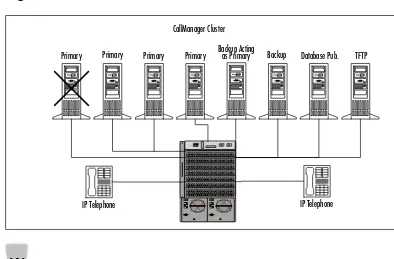
Explore the Four Primary Roles a Server Can Take On in a Cluster
■ Primary CallManager
Server
■ Backup CallManager
Server
■ Database Publisher
Server
■ Trivial File Transfer
Contents xiii
Power Cube 56
Different Queuing for Video/Voice 56
What Does the Future Hold? 58
Summary 60
Solutions Fast Track 61
Frequently Asked Questions 63
Chapter 3 AVVID Gateway Selection 65
Introduction 66
Introduction to AVVID Gateways 66
Understanding the Capabilities of Gateway
Protocols 67
Choosing a Voice Gateway Solution 69
Cisco 1750 73
Cisco 2600 73
Cisco 3600 74
VG-200 75 Configuring and Installing a VG200
with MGCP 75
Cisco MC3810 80
Cisco 7200/7500 81
Cisco AS5300/AS5800 82
Cisco DT-24+/DE-30+ 83
Catalyst 6000 84
Catalyst 4000 85
Catalyst 4224 86
ICS 7750 87
DPA 7610/7630 Voice Mail Gateway 88
Choosing a Video Gateway Solution 89
IP/VC 3510 MCU 89
IP/VC 3520 and 3525 Gateway 89
IP/VC 3530 VTA 90
IP/VC 3540 92
Multimedia Conference Manager Services 93
Summary 96
Solutions Fast Track 97
Frequently Asked Questions 100
Understand the Capabilities of Gateway Protocols
Session Initiation Protocol supports five elements of establishing and
terminating communications:
xiv Contents
Chapter 4 AVVID Clustering 101
Introduction 102
CallManager Clustering 102
Why Cluster? 103
CallManager Cluster Communications 104
Intra-Cluster Communication 104
Inter-Cluster Communication 105
Redundancy within a CallManager Cluster 106
Balanced Call Processing 108
Designing CallManager Clusters 108
Device Weights 110
Campus Clustering 112
Guidelines for Multiple Clusters 113
Video Clustering 115
Multipoint Controller Units 116
Cascading MCUs 117
Designing Clusters: A Case Study 119
Gathering Background Information 120
Coming to a Possible Solution 121
What Are the Videoconferencing
Requirements? 121
Does the Customer Need Clustering? 121
Does the Customer Need Multiple
Clusters? 122
What Hardware Is Required? 123
How Is Redundancy Achieved? 123
Configuration Summary 124
Summary 125
Solutions Fast Track 126
Frequently Asked Questions 128
Chapter 5 Voice and Video
Gatekeeper Design 131
Introduction 132
Understanding Gatekeeper Basics 132
What Is a Gatekeeper? 132
Gatekeeper Functions 133
Learn the Guidelines for Multiple Clusters
There are three
multicluster designs that may be tailored to fit your design goals:
■ Multiple clusters within
a campus or Metropolitan Area Network (MAN)
■ Multiple clusters over a
multisite WAN with distributed call processing
■ Multiple clusters over a
Contents xv
Required Functions 133
Optional Functions 135
Types of Gatekeepers 136
Multimedia Conference Manager 136
High-Performance Gatekeeper 137
Embedded Gatekeepers 138
Comparing Cisco Gatekeepers 138
Gatekeeper Flow Diagrams 139
Design Considerations 141
Using Bandwidth Limits in Your Network 142
Using Accounting within Your Network 143
Using Multicast or Unicast Addresses
to Locate the Gatekeeper 144
Designing a Large H.323 Network 144
Zone Designs 145
Implementing Zones in Your Network 146
Alternate Zone Designs 148
Routing Calls between Zones 148
A Gatekeeper’s Role in Voice and Video
Networking 152
Choosing a Gatekeeper Platform 153
Selecting a Router Hardware Platform 153
Selecting an IOS 154
Redundancy 154 Configuring HSRP between Gatekeepers 155 Using Technology Prefixes for
Redundancy 156 Using Zone Prefixes and Gatekeeper
Clusters for Redundancy 157
Placing and Configuring Gatekeepers:
A Case Study 158
Configuring Local Zones 159
Configuring the Zone Subnet 159
Configuring Zone Bandwidth 160
Configuring Remote Zones 161
Configuring the Dial Plan 161
Design a Large H.323 Network
NOTE
xvi Contents
Configuring Gateway Type 163
Configuring Gatekeeper HSRP 164
Following the Call Flow 165
Summary 166
Solutions Fast Track 166
Frequently Asked Questions 167
Chapter 6 DSPs Explained 169
Introduction 170
DSP Provisioning 170
Conferencing and Transcoding 172
Catalyst 4000 Modules 174
Catalyst 6000 Modules 176
NM-HDV Modules 181
Sample Design Scenarios 183
Branch Office 183
Enterprise Campus 184
Summary 186
Solutions Fast Track 186
Frequently Asked Questions 189
Chapter 7 AVVID Applications 191
Introduction 192
Creating Customer Contact Solutions 193
Defining the Customer Contact Channels 195
Cisco IPCC 195
Providing Voice Recording Options 205
Call Accounting, Billing, and Network
Management Solutions 208
Call Accounting and Billing Solutions 208
Designing Voice and Unified Messaging Solutions 211
Understanding Other Voice Applications 214
Summary 216
Solutions Fast Track 217
Frequently Asked Questions 219
Understand the Difference between Conferencing and Transcoding
■ Conferencing is the
process of joining multiple callers into a single multiway call. The two types of multiparticipant voice calls supported by the Cisco CallManager are ad-hoc and meet-me.
■ Transcoding is the
Contents xvii
Chapter 8 Advanced QoS for
AVVID Environments 221
Introduction 222
Using the Resource Reservation Protocol 223
What Is RSVP? 224
What RSVP Is Not 226
How Does RSVP Work? 227
Session Startup 227
Session Maintenance and Tear-Down 230
What Kind of QoS Can I Request
with RSVP? 231
Reservation Styles and Merging Flows 232
Why Do I Need RSVP on My Network? 234
Advantages of Using RSVP 235
Disadvantages of Using RSVP 235
Using Class-Based Weighted Fair Queuing 236
How Does CBWFQ Work? 236
Why Do I Need CBWFQ on My Network? 238 Case Study: Using a SQL Application
on a Slow WAN Link 240
Case Study:Total Traffic Classification
(CBWFQ in a DiffServ Model) 241
RSVP in Conjunction with CBWFQ 243
Using Low Latency Queuing 243
How Does LLQ Work? 244
Classifying Priority Traffic 245
Allocating Bandwidth 245
Limitations and Caveats 246
Why Do I Need LLQ on My Network? 246
Using Weighted Random Early Detection 247
How Does WRED Work? 247
WRED and IP Precedence 248
WRED and RSVP 249
WRED Algorithm 250
Why Do I Need WRED on My Network? 250
Using Generic Traffic Shaping and Frame
Relay Traffic Shaping 251
Understand the Advantages and Disadvantages of Using RSVP
Advantages:
■ Admissions Control
RSVP not only provides QoS, but also helps other applications by not transmitting when the network is busy.
■ Network
Independence/ Flexibility RSVP is not dependent on a particular networking architecture.
■ Interoperability RSVP
works inside existing protocols and with other QoS mechanisms.
■ Distributed RSVP is a
distributed service and therefore has no central point of failure.
■ Transparency RSVP
can tunnel across an RSVP-unaware network. Disadvantages:
■ Scaling Issues
Multifield classification and statefulness of reservations may consume memory and CPU resources.
■ Route selection and
stability The shortest path may not have available resources, and the active path may go down.
■ Setup time An
xviii Contents
Token Bucket 252
How Does GTS Work? 253
Why Do I Need GTS on My Network? 254
How Does FRTS Work? 255
Why Do I Need FRTS on My Network? 256
Running in Distributed Mode 260
Features Supported in Distributed Mode 260
IOS Versions 261
Operational Differences 261
Restrictions 262
Using Link Fragmentation and Interleaving 263
How Does LFI Work? 265
LFI with Multilink Point-to-Point
Protocol 266
How Can This Be Useful on My Network? 266
Understanding RTP Header Compression 267
How Does RTP Header Compression Work? 267 When Would I Need RTP Header
Compression? 269 Summary 270
Solutions Fast Track 272
Frequently Asked Questions 275
Chapter 9 AVVID Dial Plans 279
Introduction 280 Problems Facing the Integration of Voice
and Data 280
What Is a Dial Plan? 281
Configuring Dial Peers for Use 283
Configuring Dial Peers for POTS 283
Configuring Dial Peers for VoIP 286
Dial Peers for Inbound and
Outbound Calls 290
Route Pattern (On-Net) 292
Routing Outbound Calls through
the PSTN 293
Contents xix
Internal Calls 295
External Calls 296
Route Pattern 297
What Is Digit Manipulation, and How
Do You Configure It? 297
Route List 299
Telephony Devices 300
Digit Translation Tables 300
Fixed-Length Dial Peers versus
Variable-Length Dial Peers 303
What Is Two-Stage Dialing? 305
Creation of Calling Restrictions and
Configuration of Dial Plan Groups 306
Partitioning with Cisco CallManager 307
Creating a Calling Search Space 307
Guidelines for the Design and Implementation
of Dial Plans 309
Setting up Single-Site Campuses 309
Design Considerations for the Creation
of a Dial Plan 312
Creating a Dial Plan for a Multisite
Organization 315 The Role and Configuration of a Cisco
CallManager and Gatekeeper 315
The Cisco CallManager Model 316
The Gatekeeper Model 316
The Hybrid Model 317
Video Dial Plan Architecture 319
Gateway 321
Proxy Gateway 321
The H.323 Gatekeeper 322
Configuring Video Dial Peers 323
Summary 325
Solutions Fast Track 326
Frequently Asked Questions 332
Designing & Planning…
xx Contents
Chapter 10 Designing and
Implementing Single Site Solutions 335
Introduction 336 Using AVVID Applications in IP Telephony
Single Site Solutions 336
Designing the Voice over IP Network 338
Considerations for the LAN 338
Connecting the Site to External
Telephony Systems 342
Connecting the Single Site Back to the
Corporate System 343
Connecting the Single Site Back to
Other Small Sites 344
Choosing a Voice-Capable Gateway 346
Types of Voice-Capable Gateways 346
Cost-Effective Gateways for Small Sites 347
Cisco IOS Solutions for Voice Gateways 348
Problems Using the Voice Gateway for
Combined Data Access 349
Modifying an Existing Network to Support
Voice over IP 349
This Must Be a Pure Cisco Solution! 350
Deciding Which Type of Public
Telephony Access to Use 352
Performing a Network Assessment of
the Infrastructure 353
Engineering a Mixed Vendor Solution 354
Using AVVID Applications in Single-Site
Solutions 354
Using Cisco CallManager 355
Understanding the Component Parts
of CallManager 355
Installing CallManager 356
Performing Basic Configuration Tasks 357
Performing Advanced Configuration
Tasks 362
A Typical Small Site Traditional Data Network
Internet
Router
3524 Switch
Network Printer
Server
Server User
Contents xxi
Troubleshooting Problems with
CallManager 364
Using Cisco Unity Voice Messaging 365
A Word about Exchange Server v5.5 366
Installing the Unity Messaging System 366
Creating Unity User Accounts
from Exchange Server’s Mailboxes 366
Using the IP SoftPhone 368
Introducing the SoftPhone 368
Installing SoftPhone 369
Configuring SoftPhone 369
Troubleshooting SoftPhone Issues 370
Using AVVID Applications in Video Single-Site
Solutions 371
Designing the IP Network for Multicasting 371
Local Area Networks 373
Wide Area Network Considerations 375
Remote Access Solutions for Video
Presentations 376
Cisco’s IP Television Solution 377
Uses for IP/TV 378
Devices Used in IP/TV Solutions 379
Single Site Solutions for IP/TV 380
Cisco’s IP Videoconferencing Solution 381
Equipment Uses in IP/VC Solutions 382
Good Examples of Using IP/VC for
Small Sites 383
Why IP/VC May Be Bad for Single Sites 383
Summary 385
Solutions Fast Track 385
Frequently Asked Questions 387
Chapter 11 Designing and Implementing
Multisite Solutions 391
Introduction 392 IP Telephony Multisite Centralized Call
xxii Contents
Wide Area Network Considerations 393
The Gatekeeper Function 394
Voice-Capable Gateways 395
Choosing Frame Relay or Leased Lines
for Site-to-Site Connectivity 396
Using the Gateway for Data and
Firewall Access Control 401
Handling LAN Problems for Multiple Sites 402
Preparing the Head Office LAN to
Support CallManager Clusters 403
Making Changes to the LAN to
Handle Large Call Volumes 405
Providing Multiple Ingress/Egress
Points to Sites 405
Designing the CallManager Centralized
Solution 407
Enterprise Dial Plans 407
Installing Backup CallManagers for
Redundancy 409 Assuring Constant User Connectivity
to CallManager 409
Disaster Recovery for Centralized
CallManager Solutions 411
IP Telephony Multisite Distributed Call
Processing Solutions 412
CallManager Designs and Issues 412
Extending Enterprise Dial Plans to
the Field CallManagers 413
Supporting Distributed Call Processing
with Overall Design Changes 414
Disaster Recovery for Distributed
CallManager Solutions 415
WAN Designs that Support Distributed
CallManager 416
Full Meshed WAN Designs 416
Partially Meshed WAN Designs 418
Use Voice-Capable Gateways
A voice-capable gateway is a Cisco router that runs the MGCP IOS firmware that performs processing for voice calls on the local network to local or external destinations. The voice-capable gateways for branch offices are:
■ Model 175x for small
site gateways, for up to 10 users
■ Model 26xx for small
sites, for up to 50 users
■ Mixed variations of
Contents xxiii
Determining Network Impact of
Distributed CallManager Clusters 419
LAN Issues for CallManager Clusters 419
WAN Performance between
CallManagers 420
Unity Messaging Issues 421
Multisite AVVID Solutions 422
Designing the Enterprise IP Network for
Multicasting 422 Configuring the Routers to Support
Multicasting 424
Wide Area Network Considerations 426
Cisco’s IP Television Solution 427
Using IP/TV with Branch Offices 427
Choosing Devices for Enterprise
IP/TV Solutions 429
Cisco’s IP Videoconferencing Solution 429
Using IP/VC for Multiple Sites 430
Why IP/VC Can Be Damaging to an
Enterprise 431
Creating the Auto Attendant 431
Using Web Attendant 433
IP Interactive Voice Response System 433
Summary 436
Solutions Fast Track 437
Frequently Asked Questions 438
Cisco AVVID and IP Telephony
Design & Implementation Fast Track 441
The business benefits compelling enterprises to assess and deploy IP telephony solu-tions are many.While many of the cost savings benefits still apply with reduced costs for moves, adds and changes (MACs), infrastructure consolidation, and international toll bypass, perhaps more compelling are the new applications now available. “Click to dial,” “follow-me,” unified messaging, and customized XML applications running on IP phones can change the way organizations function to gain advantage in the increasingly competitive business landscape.
Many lessons have already been learned from the rapid adoption of Cisco’s AVVID IP Telephony product line.While the business justification is compelling, organizations must cost effectively integrate “old world” technologies with the new, engineer packet transport networks for quality of service, simultaneously bolster tra-ditional telephony and IP skills, and continuously exercise proper risk management. The purpose of this book is to help readers overcome the inherent complexities of IP telephony so that its promise can be fully realized.
Those interested in implementing, administering, or gaining certification with AVVID IP Telephony should read this book. A survey of “old world” technologies is presented to contrast to the “new world” of IP telephony and its components.
Gateway selection, high availability CallManager clustering, H.323 gatekeeper design, DSP provisioning, dial plans, and QoS are explained. An interesting review of appli-cable protocols, engineering for complex multiple site deployments, and an overview of IP telephony applications are also included.
The lessons to be learned from this book have been learned by Callisma’s highly skilled team of technology and project management professionals who specialize in the design and implementation of complex IP telephony networks.We help our clients leverage competitive advantage through the judicious application of networking technologies via strategic business planning, design, engineering, and implementation services.
—Ralph Troupe, President and CEO, Callisma
xxv
Old World
Technologies
Solutions in this chapter:
■ Introduction to PBXs ■ Looking Inside the PBX
■ Interpreting PBX Terminology ■ Working with Analog Systems ■ Benefiting from Digital Systems ■ Providing Video Services
; Summary
; Solutions Fast Track
; Frequently Asked Questions
Chapter 1
2 Chapter 1 • Old World Technologies
Introduction
The modern Private Branch Exchange (PBX) system is an old world technology in much the same way an automobile is—there may be better and faster trans-portation alternatives, but the car’s place in daily life, even an older car, is some-what assured. Cars are used to get people and things from place to place with independence, and they are generally efficient and reliable devices. As with the automobile, the reality is that the PBX in many corporations is not going to depart from the landscape any time soon.
As with the car, telephone systems can be practical or luxurious—ranging from a single line to older key systems to full-function PBX-based conferencing systems with multiple features.The biggest factor in these systems is that a tradi-tional phone is reliable, easy to operate (at least for the end user), and econom-ical.The PBX is a great example of this old-is-good construct, and in many companies this will be true for some time to come.The term old world should not be understood as meaning defunct.
As such, this chapter will focus on these systems in the context of both their legacy status in telecommunications and their position in newer, more advanced implementations. One of these new models must include Cisco System’s vision of the next generation PBX, which is part of the Architecture for Voice,Video, and Integrated Data (AVVID). Please note that Cisco’s vision of the next generation PBX is the current generation of CallManager and IP phone.The term next
generation PBX relates to the idea that legacy PBX systems, including Meridian and
Sidemen’s, will fade into the historical record of telecommunications, following a period of migration.
Under this vision, PBX-attached phones and services will be augmented with Internet Protocol (IP)-based telephony and new integrated services, including video, desktop integration, and data services. Many of these functions and offer-ings are available today, and a clear roadmap of what can be availed in the next year is easily identified. However, there are still hurdles to overcome, including reliability and simplicity. It is important to remember that while AVVID can pro-vide many features in the network and easily replace the modern PBX in many organizations, the hurdles to this convergence include capital costs, support costs, functionality, training, and reliability.
www.syngress.com
provide a foundation for those entering the AVVID environment of converging voice with data and video information.
Introduction to PBXs
The evolution of phone systems starts with the early experiments of Alexander Graham Bell. In 1875, communication over long distances was handled by the telegraph, a simple device that would transmit electrical pulses across a wire. Though there is some dispute regarding Mr. Bell’s status as the inventor of the basic telephone, he and his estate have successfully defended the original patent on the invention. For our purposes, the transmission of sound over electricity is what’s significant.
Early telephones were little more than extensions of this original discovery, and party lines and local phone companies were quite common.The party line placed a multipoint drop from the phone company to a number of homes, and the operator would signal an incoming call by altering the ring frequency to a custom signal (for example, one long and three short rings).These systems were prone to the same issues as broadcast media today, especially eavesdropping.
By 1950, a human operator was needed in a more centralized fashion to ser-vice the hundreds of phones that were installed. Human operators manually con-nected calls at the physical layer by using huge switchboards, and call setup times were very long.This system was a solid first-generation effort to link party lines and private lines into a national network. However, many of today’s advanced features, including conferencing, alternate billing, and voice mail were inconceiv-able then.
In the last half of the twentieth century, phone technology made huge strides, including analog switching, digital switching, trunking, and the first versions of the modern PBX.The human operator was replaced with automated switches that processed calls automatically, and corporations were able to provide privately administered services that rivaled the phone company.You may recall that the original public phone systems were virtually always installed and owned by the government or by single corporations—a far cry from the divergent world of today in many countries.
While the PBX remains an entrenched fixture in many organizations, like the mainframe computer, it also gave life to the next generation of successors and augmenters. In the mainframe world this is the personal computer, and in the voice and PBX world this is the IP telephone. Many in the AVVID arena con-sider the IP telephone a cornerstone, because it is the simplest of devices for the
4 Chapter 1 • Old World Technologies
end user to operate and because it integrates so well with the additional services promised by the technology.Voice over IP (VoIP) is the common term used for these systems. For completeness, and to simplify installation, IP was selected, as it is the most common protocol in the current networking world.
N
OTEIn subsequent chapters, you will likely find that many of the problems encountered with VoIP systems, including latency, queuing, and routing, are related to the early decision of using IP as a protocol.
Designing with Legacy Systems in Mind
Before you tackle the converged world of Cisco’s AVVID—even if you configure PBX systems daily—it may be a good idea to read this chapter to renew your understanding of what a PBX is and how it works.
N
OTEPlease note that this chapter is written from the Cisco AVVID perspective as it relates to PBX systems and telephony, and, as such, some definitions and concepts will differ from the phone company or PBX system origins. These are not errors, but rather, are simplifications of these terms and ideas to a common, related reference point. For example, FXS and FXO in carrier terms can refer to other companies and their respective connections.
However, before we enter the world of the PBX, there is a legacy system that needs introduction.This is the key system. A key system is a multiline phone his-torically found in offices with up to ten users. It is best thought of as those old, clicking phones with the large, lit buttons.
It is possible to find such systems servicing up to 100 users, however, modern economics and the lack of advanced features makes these installations less
common, and well-suited for replacement.
Old World Technologies • Chapter 1 5
maintained between the number of phones and the number of outside lines. As such, unlike the PBX, these systems do not scale to hundreds of users, nor do they save circuit charges.
So, why do we introduce the key system before the PBX? Well, the key system is to the PBX what, presumably, the PBX is to VoIP and AVVID.The ser-vices provided by the key system were invaluable to companies of the mid-twen-tieth century, as calls needed to be routed from one resource to another. In addition, many PBXs today emulate the key system’s multiline presence, and this service is available with the current offering of AVVID. As you read about the internal functions of the PBX, consider the legacy of phone and key systems pre-viously described, and consider those services in the VoIP environment.
www.syngress.com
What Voice Designers Do
The art of voice system design is very different from data installations, although there are similarities. A voice designer is typically confronted with two challenges—the tariff, or cost-per-minute-per-mile, and the redundancy within the network itself. These designs are based on the number of channels needed, and are greatly simplified by the lack of routing protocols and intelligent end-stations.
For example, in a data network installation, the designer will typi-cally draw upon elements of the three-tier model. This model defines a
network core, which interconnects different distribution layer devices,
and these, in turn, connect to the access layer, which services users. This design is based upon the concept that data packets will take alternate paths between devices based on load, in addition to the premise that the network devices themselves are prone to failure.
Voice designs are different in regards to both hierarchy and redun-dancy. First, the modern PBX is internally self-redundant, which means the physical box itself attempts to provide its own redundancy. Data net-working systems have only recently reached this level of redundancy, and, typically, they still experience a short outage as the system changes from the primary to standby engine. In addition, the illusion of redun-dancy within the box in data networking often requires alterations to the connected devices—Cisco’s Hot Standby Router Protocol (HSRP) is a good example of how workstations are tricked into thinking that two
Designing & Planning…
6 Chapter 1 • Old World Technologies
physically redundant routers are actually one device. The trick is a shared IP address and virtual Media Access Control (MAC) address to make two routers appear as a single router. This, coupled with redundant Supervisor and routing engines, can create the appearance of a redun-dancy intradevice—however, because the end station has intelligence (unlike the phone), these installations are more complex.
As noted, the end stations in voice networks do not have intelli-gence, which greatly simplifies the redundancy model. The internally self-redundant PBX, therefore, is not concerned with protocols and other user-side functions to provide redundancy. Within the chassis, a PBX only needs to provide redundant power, redundant processing, and alternate egress paths. Advanced systems may also provide an ability to redirect the physical port to another interface (engine) so the user’s phone is also serviced in the event of a hardware failure. This is an uncommon installation, however. Note that all of these redundancies occur intrachassis, and, because of the static nature of the switching paths, no convergence (compared to IP routing) occurs.
By now, you have likely guessed that the hierarchical design con-siderations in many PBX systems are also very different from routers and switches. For example, it is rare to have a PBX system with three tiers. Most large installations are serviced with two tiers sufficiently. These designs parallel hub-and-spoke data models much more than the three-tier requirements of large data networks. Part of this variance in design is availed by the constant bit-rate of voice and the use of time division multiplexing (TDM). Thus, a designer in a PBX environment need only concern himself or herself with the number of concurrent calls between points. All traffic consumes the same amount of bandwidth (a DS-0 in most cases).
Let’s look at that another way. A data designer reviewing the capacity of a link needs two variables—the number of flows and the size of each flow. This is analogous to a freeway where semi trailers use the same road as cars and motorcycles. Clearly the roadway can service more motorcycles than trucks. In contrast, the voice designer needs only one variable in addition to time—the number of flows. All flows are exactly the same—in the highway example, they would all be Volkswagens. Thus, a designer need only consider the number of flows that will occur at the same moment. This may result in a peak of 12 calls at 2:00 P.M.—a figure easily within the capacity of a T-1 circuit including
Old World Technologies • Chapter 1 7
Looking Inside the PBX
A PBX consists of hardware and software designed to emulate the public tele-phone system within a company, and provide paths into the Public Switched Telephone Network (PSTN).These systems can be categorized into four primary areas, with each area containing one or more functions:
■ Extension termination
■ Trunk termination
■ System logic and call processing
■ Switching
These functions are illustrated in Figure 1.1 and described in greater detail in the next sections.
Implementing Extension Termination
Each resource on the private side of the PBX is commonly called an extension. These devices have a direct, one-for-one connection to a port on the PBX.These connections are typically digital, however, analog extensions for modems and other services are available, and you will find that the term Foreign Exchange Station (FXS) is commonly used for analog stations such as fax machines and modems attached to the PBX (although this is an erroneous term). In addition, there is a large population of PBXs attached, via analog links, to the extensions, and while the current connections from many vendors are digital, there is nothing wrong with the analog connections apart from the limitations of the transport.Wiring for these connections is voice grade. However, it may include
[image:34.612.84.473.292.416.2]www.syngress.com
Figure 1.1The Basic Functions of a PBX
Extension Termination
Trunk Termination
PSTN
Other PBX Systems System Logic /
Call Processing
8 Chapter 1 • Old World Technologies
Category-3 or Category-5, and two- or four-wire (single pair or two pair) installa-tions are common.The PBX must also provide these extensions with dial tone generation, just as the public phone switch provides this service for non-PBX attached phones.These interfaces also pass the Dual Tone Multi-Frequency (DTMF) tones to the call processing engine that will be described shortly.
Implementing Trunk Termination
While not required, most PBX systems are connected to at least one T-1 circuit for connectivity to either the PSTN or another PBX within the company. A
trunk is a T-1 or other type of circuit, which can carry multiple channels, or time
division multiplexed (TDM) data streams. Recall that these connections can carry up to 24 voice connections depending on their framing and signaling. Please note that trunks can also use the E-1 standard, which allows for 30 user channels.
N
OTESome trunks are called tie lines, which are simply trunks used for connec-tions to another PBX. In some instances these connecconnec-tions are only capable of carrying voice channels; additional functions are provided in others. One example is Siemens’ CorNet, which can provide most intra-PBX services between inter-intra-PBX devices.
Call Processing and System Logic
In addition to the user interface found on most PBX systems, there is also logic that controls the flow of calls.The basic process is based on dialing plans, which compare the DTMF tones to the route plans and paths configured on the PBX. These tones represent the numeric values of the buttons, in addition to the asterisk (*) and pound (#) keys. Using the phone number or extension dialed, the PBX routes the call either to the external trunk (the link to the public net-work), to another PBX within the company (which is carried on an internal trunk), or to another extension within the PBX.This addressing is signaled using the DTMF tones.
Old World Technologies • Chapter 1 9
happen if that path failed? Simply, the administrator would specify an alternate path—analogous to a floating static route in Cisco routing.These less-preferred routes could be configured for call overflow (where insufficient capacity exists on the primary link) or trunk failure (where the link must completely fail before taking an alternate path).This decision adds a dynamic to the typically static limi-tations of the PBX forwarding system.
N
OTEMost PBX phones are digitally connected to the PBX and do not send the actual DTMF tones from the phone to the switch. Traditional analog phones and some PBX phones will send the actual tones to be inter-preted by the switch. However, the call routing is still based on the numbers pressed and received, and the non-Signaling System 7 (SS7) signaling is either proprietary or DTMF.
As a designer, you may specify that long-distance calls (indicated with a 9, fol-lowed by a ten-digit number, for example) should use a trunk to long-distance provider A, which also provides the lowest cost per minute to the company.The alternate path, configured for overflow calls, might go to long-distance company B, which may also charge more per call. A backup path, using the local exchange carrier, may be configured in the event the first two paths are unusable.
The system logic and call processing functions typically include collections of billing information and other call accounting data that can be used for capacity planning and charge-back services.These functions are independent of the final PBX functional area: switching.
Switching
In order to better understand the diversity of the call routing and circuit switching processes, each is presented as a distinct element in this section. In practice, you will likely find that the two are so inter-related as to be one. In many systems, however, there is a difference.
Switching in the PBX system is the mapping of a channel on one interface to another channel on another interface. For example, this may involve linking a DS-0 to a DS-1 (T-1), or an FXS port to a T-1 trunk on another PBX.The logic that decides which path to be taken is part of the call processing function. Once established, however, the switching of these TDM packets is transparent to the
10 Chapter 1 • Old World Technologies
processor until the call is torn down.This is a significant difference between IP networking and voice traffic, as a routing process typically takes place for each packet—in voice, the call setup only requires processing before the call begins.
It is significant to note that, as with data networking switches, the technology can be blocking or nonblocking and this, coupled with other factors, can greatly impact total capacity. For example, Siemens’ blocking architecture can switch up to 5,760 ports, while the nonblocking Intecom can switch up to 60,000 ports.
Establishing Links Outside the PBX
The systems outside the PBX are actually pretty simple once you understand the internal systems.The voice world is made up of trunks, which interconnect public or private switches.The basic functionality of these devices is no different for our purposes.
However, there are a few things you should consider when thinking of external PBX resources.These include the wide variety of phone numbers in the international phone network, and the signaling protocol between switches in the public network.
As you may know, calling internationally from your respective country can be either a simple or difficult process.The administration of all the possible numbers is also a daunting task. In either the legacy or AVVID environment, you’ll need to work with these external-dialing plans to allow users to connect to other systems.
Consider your home telephone for a moment. In the United States, a call to Israel would require calling 011 (the international escape code), 972 (the interna-tional country code for Israel), 3 (the city code, similar to an area code), and the local number, which may be six or seven digits. However, note that in some countries, the city code may appear as 03. A call to Belarus would use a country code of 375, and the city code and number may only contain five digits. A call from another country to the US would require a three-digit area code and a seven-digit number. As a PBX programmer, the system must be capable of han-dling all the digits provided and routing the call to the correct destination.
Old World Technologies • Chapter 1 11
Belarus, from Denver to Tel Aviv to Mozyr.This dialing plan addresses two fac-tors: call routing and call tariffing.
However, let’s presume our call to Mozyr is cheaper using the public network and employing a link between New York and London. How does the network understand our call and establish a path between Denver and Mozyr?
Well, this is the second point of external systems.The switches in the network need to signal each other using a common protocol. In many networks, this pro-tocol is called Signaling System 7 (SS7).
Data network designers are probably used to in-band signaling, where the IP address is part of each packet. No such mechanism exists in voice networks. Rather, the signaling is out-of-band, or independent of the actual data. SS7 is used between the switches to provide this dialog, and, in our call to Mozyr, the Denver phone company switch might use SS7 to signal a path from Denver to Chicago, and another link from Chicago to New York. Once the path is built using SS7, a voice link is established and the call commences. Please note that this does not occur with the PBX private connection to Jerusalem, as this is in-net-work, and SS7 is typically not used in private switch-to-switch communications.
www.syngress.com
How PBX Installation Differs from Router Installation
Most readers of this book are likely entering into the world of PBX sys-tems from the data world. In fact, many of you may never have installed a PBX or voice system. However, whether you approach data from a voice background or voice from a data background, the reality is that at a high level the two differ less than you might imagine.
It would be inappropriate to enter into the commands and syntax of PBX configuration here—for one, which system would we use as a reference? There are many PBX systems, each with different software versions and hardware options, and each revision of code introduces new commands and syntax. This is not unlike an academic conversation on router configuration—Cisco or Nortel, Multilayer Switch Feature Card (MSFC) or Route Switch Module (RSM) or Route Switch Processor (RSP)-2. In fact, this is the first of the ways in which the systems parallel one another. PBXs and routers both have their own unique features and commands based on the vendor and the version of code.
Configuring & Implementing…
12 Chapter 1 • Old World Technologies
Interpreting PBX Terminology
The world of telecommunications and PBX systems includes a vocabulary unique unto itself.You may find that many of the words and acronyms are familiar and common if your background is based in the data world. Nevertheless, there are a number of new terms and concepts that need to be understood before tackling the integration of voice and data systems. In addition, some acronyms have multiple
In the previous sidebar, “What Voice Designers Do,” we discussed the design and deployment considerations of a modern PBX. We also saw the similarities between data systems and voice PBXs. These simi-larities include redundancy, cost/performance, and design limitations. PBX systems augment these similarities with a few distinct differences, including:
■ Power Electrical requirements in PBX systems are frequently
48 volt DC. Data network devices are often 120 volt AC.
■ Wiring It is rare that a PBX system will require Category 5
cabling for connectivity, unlike Ethernet. In addition, it is uncommon to terminate voice grade wiring on patch panels. Rather, voice wiring uses punch-down blocks that hold each bare wire onto a clip. Requirements such as maintaining twists and staying under 100 meters are not part of the typ-ical voice installation.
■ Dial Plan Unlike IP routers, voice systems rely on static
routing tables when forwarding calls. Calls are routed based on a match with the destination number—unlike data net-works, the source address is rarely used for call routing. The static route map will define a preferred path, an alternate path, and, sometimes, tertiary paths for each number within the environment.
■ Circuits In the data world, most circuits are billed at a
Old World Technologies • Chapter 1 13
meanings depending on whether you’re discussing voice or data. For example, the acronym CDP, to a Cisco router guru, likely means Cisco Discovery Protocol. In the voice world this term refers to Coordinated Dial Plan.
So, what are the common PBX terms you may encounter? Well, the first is a T-1. A T-1 circuit is capable of carrying up to 24 voice channels (DS-0), depending on provisioning.The total available bandwidth is 1.544 Mbps, although the Integrated Services Digital Network (ISDN) Primary Rate Interface (PRI), which uses T-1 framing, takes one DS-0 for upper layer signaling.The European standard is called E-1. It provides, however, 2.048 Mbps of bandwidth, or 32 chan-nels. An E-1-based PRI, on the other hand, uses two of these channels for sig-naling and framing, and thus, allows for 30 user-based voice channels. In addition to the T-1 ISDN PRI , the circuit may also be configured as channel associated signaling (CAS) or ear-and-mouth (E&M).
It is warranted to expand on ear-and-mouth technology slightly in this forum, as E&M ports are found on the Cisco hardware platforms and many interconnections will make use of this specification. E&M can also stand for earth
and magneto, amongst other variations, and is simply another signaling
method-ology. E&M, like FXO and FXS, is an analog specification, unlike ISDN, which is digital. In addition, FXO is available for PSTN or PBX connections, whereas E&M is for trunk or tie lines between switches—they are network-to-network links. As such, some Cisco installations use the VIC-2E/M interface for connec-tions to voice mail or legacy PBX systems. Please note that this module supports both the two and four wire specifications of E&M for types I, II, III, and V.
These links may also be loop start, in which removing the receiver from the hook closes a circuit and creates a loop, allowing connections. Or they may be ground start, where an earth ground is needed to complete the loop and allow connectivity.
N
OTEIt is important to remember that voice services are based on time divi-sion multiplexing, or TDM. This is the basis for most connections in the voice world, just as it is for T-1 signaling. A DS-0 is a single voice digital channel of traditional voice bandwidth—8Hz at 8 bits per sample.
The term central office is a legacy description of the local telephone company’s termination point for all numbers in a given area, and commonly connects to
14 Chapter 1 • Old World Technologies
PBXs via T-1s. Historically these were centrally located and copper was run from each building in the town to the central office.Today, a wide variety of devices are deployed to convert copper local loops into fiber and the central office termi-nates a small number of fiber pairs that service hundreds of lines.The central office would also provide a Direct Inward Dial (DID), although such connections are typically bi-directional today. In order to directly connect from the public phone system to a PBX, the caller must either be manually routed to the exten-sion or a relationship between the extenexten-sion and a public number must be estab-lished. DID provides the latter service—a block of numbers can be assigned to a trunk line from the telephone provider to the PBX, and the PBX administrator can route those numbers to related extensions. Figure 1.2 illustrates the logical configuration of number 415-555-1234 to extension 51234. Please note that it is quite common to create five-digit extensions in North America that relate to the assigned DID numbers.
To understand the routing in the phone network, one needs to understand Coordinated Dial Plans (CDP). (As we mentioned earlier in this section, if you are entering the world of telephony from the Cisco router, you are no doubt thinking Cisco Discovery Protocol for CDP.The acronym CDP stands for both actually, depending on your perspective.) A coordinated dial plan is analogous to addressing in IP routing—the dial plan defines what numbers exist on your net-work and how callers will reach phones outside your company. (For example, a
Figure 1.2Logical View of Direct Inward Dialing
PSTN
PBX Receiver
51706
52013
707-555-1234 Caller Configuration within the phone
company's switch directs all calls to 415-995-xxxx to the PBX. Extension 51706 maps to 415-995-1706.
Old World Technologies • Chapter 1 15
coordinated dial plan may require a nine to be dialed before an external number.) The term call routing has two meanings, however, that overlap slightly.The first context is the physical act of routing a call through the network. For example, calls to 312 are destined for Chicago, which is a long-distance call requiring a service provider beyond the PBX.The second meaning involves the act of pro-cessing that call—there may be three alternate paths to Chicago, and, based on availability, price, and preference, an administrator can route the call along any of those paths.
N
OTERouting in PBX systems is static, unlike data networks, which typically use dynamic routing.
In the voice world, telecommunications services are billed at various amounts based on the tariff involved. A flat rate structure removes per-minute charges from the billing calculation. Other tariffs can remove distance or other parameters from the calculation.
It is also important to consider the historical import of which end is which in the voice world. For example, you may hear the term tip-and-ring in single pair copper connections, which relates to which end supplies the voltage on the wire. In the same manner, there are also foreign exchanges, which have slightly different meanings depending on your background.
N
OTEMost voice copper wires are described in pairs—thus, a two-wire connec-tion is a single pair, while a four-wire connecconnec-tion is a double pair, or two
pair. Traditional Category 5 wiring would be four pair.
For our purposes, we will describe a Foreign Exchange Station (FXS) as a link between the switch and an extension.This term is sometimes used to describe a connection that services an analog device within the company attached to the PBX, such as a fax machine or modem. If you’ve worked within the phone com-pany, this term may be defined differently; however, this definition is best in the context of AVVID. In contrast, a Foreign Exchange Office (FXO) link is between
16 Chapter 1 • Old World Technologies
the PBX and the central office. It is a DS-0 and analog, and it is tariffed at a flat-rate.There may be instances when local services are desired, but ISDN or T-1 bandwidths are not needed. FXO connections can be used to service these situa-tions, and can also be used to provide local 911 service in the event all other calls traverse the private network to a main site in another location.
Working with Analog Systems
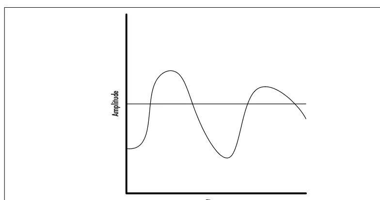
Analog waves, unlike digital signaling, have a range of values that represent trans-mitted information.These signals are susceptible to many forms of interference, and, visually represented, they appear as a continuous wave. Figure 1.3 illustrates a common analog waveform.
As shown, there is no absolute value within the wave—it varies as the strength of the signal increases or decreases.This introduces one of the primary problems with analog systems, because one must consider the introduction of static and amplification in the waveform.To illustrate this, consider Figure 1.4.
[image:43.612.63.454.258.462.2]Note that the waveform is now comprised of higher highs and lower lows, and spikes of noise have slightly altered the waveform.The receiver will perceive this as a change in pitch, volume, and tone, and, should this degradation continue through multiple amplifiers and noise-prone circuits, the original waveform may be so disrupted that communications is impossible.
Figure 1.3The Analog Continuous Waveform
Time
Old World Technologies • Chapter 1 17
The phone system was originally designed to make use of limited frequencies to transmit voice signals. As human speech consumed a very small spectrum, the analog telephone equipment could perform the relatively simple mechanical to electrical conversion necessary to propagate a voice over long distances.
As with record players and compact disc/DVD players, it is likely that both analog systems and their digital counterparts will remain for some time. As such, it is important to consider how analog systems integrate into digital environments such as VoIP or AVVID. Simply put, such installations will require conversions from analog to digital, and, as with old 45s, the quality and performance of the older systems may be limited. Of course, it will also be familiar and, at a political level, you may find reluctance in getting users off their non-VoIP systems.
In the next section we will present digital systems. It needs to be noted here, however, that there is a way to convert from analog to digital—a conversion addressed by a coder-decoder (CODEC).The actual conversion is effectively a sampling of the analog stream and a digital representation of that stream. Of course, the conversion can take the digital data and interpolate an analog wave-form.The conversion is not without potential loss, unfortunately, and it is best to limit the number of conversions within a data flow. Recall that FXO, FXS, and E&M are all analog connection methods.
[image:44.612.80.472.83.290.2]www.syngress.com
Figure 1.4The Amplification of Static in an Analog Waveform
Time
18 Chapter 1 • Old World Technologies
Benefiting from Digital Systems
Digital signals are binary in nature, and are either on or off.These states are very precise, and unlike the continuous waveform that exists in analog systems, the signal can be regenerated with accuracy regardless of noise and interference.This is not to infer that digital signals are impervious to noise and static, but, rather, these problems are easily detected in a digital system and can be compensated for. This is made possible by the absolute values transmitted on the wire. Figure 1.5 illustrates a digital waveform.
Digital systems in telephony can take advantage of this binary state and aug-ment communications with additional features that are not available in analog systems, including compression.This allows speech to be sent in fewer bits than in analog format, and, in the migration to AVVID, the data stream can actually be stopped when a party stops speaking.This can greatly increase the volume of connections that can concurrently occur in the network. ISDN PRI is one of the most popular digital connections.
Providing Video Services
It is atypical to include the PBX as part of a video solution; however, some advanced PBX systems do provide video services.These connections can either
Figure 1.5The Digital Waveform
Time