UML Xtra-Light: How to Specify Your Hardware Requirements
by Milan Kratochvil and Barry McGibbon
ISBN:0521892422
Cambridge University Press © 2003 (106 pages)
Written to help business managers communicate with the technical members of their staff, this brief guide offers advice on using UML notation to describe business objectives to software developers.
Table of Contents Back Cover Comments
Table of Contents
UML Xtra-Light—How to Specify Your Software Requirements Foreword
Preface
Chapter 1- Introduction
Chapter 2- Aligning to the Business
Chapter 3- Adding Rigor to the Requirements Chapter 4- Sketching the Inside Structure Chapter 5- Sketching the Inside Dynamics Chapter 6- Moving Toward Components
Chapter 7- Mapping from Classes to Data Models Chapter 8- Concluding Remarks
Some Suggested Readings Index
UML Xtra-Light-How to Specify Your
Software Requirements
Milan Kratochvíl Barry McGibbon
PUBLISHED BY THE PRESS SYNDICATE OF THE UNIVERSITY OF CAMBRIDGE
The Pitt Building, Trumpington Street, Cambridge, United Kingdom
CAMBRIDGE UNIVERSITY PRESS
The Edinburgh Building, Cambridge CB2 2RU, UK 40 West 20th Street, New York, NY 10011-4211, USA 477 Williamstown Road, Port Melbourne, VIC 3207, Australia Ruiz de Alarcón 13, 28014 Madrid, Spain
Dock House, The Waterfront, Cape Town 8001, South Africa
http://80-www.cambridge.org.ezproxy.library.drexel.edu
© Milan Kratochvíl and Barry McGibbon 2002
This book is in copyright. Subject to statutory exception and to the provisions of relevant collective licensing agreements, no reproduction of any part may take place without
the written permission of Cambridge University Press.
Any product mentioned in this book may be a trademark of its company.
UMLTM is a registered trademark of the Object Management Group.
UML logo used with permission from the Object Management Group.
First published 2002
Printed in the United States of America
Typefaces Stone Serif 10.5/13 pt., Stone Sans, and Informal System QuarkXPress® [GH]
A catalogue record for this book is available from the British Library.
Library of Congress Cataloging in Publication Data
Kratochvíl, Milan.
UML xtra-light : how to specify your software requirements / Milan Kratochvíl, Barry McGibbon.
p. cm.
Includes bibliographical references and index. ISBN 0-521-89242-2 1. Application software - Development. 2. UML (Computer science) I. McGibbon, Barry, 1947- II. Title.
QA76.76.A65 K72 2002 005.1 - dc21
200219253 ISBN 0 521 89242 2 paperback
To my father, Jiří, and to generations of composers before him who realized that architectural standards, components, and reuse all boost creativity and invention.
Foreword
Yet another book about UML! Since its initial version, the Unified Modeling Language has gone an impressive way in the IT community. Over the past couple of years, we have been loading our bookcase with quite a few UML books. Many of them deal with applying or extending UML for a specific domain: UML for project management, UML for business modeling, UML for Java, real-time UML, UML for components, UML for web applications, and so forth.
This book takes a somewhat different and, in our opinion, long-awaited approach. It goes back to the basics of UML: improving the communication
among different stakeholders of a (software) project. As the authors of the book write: 'a UML made easy for people who specify, buy, or manage complex software systems.' Many of these stakeholders are non-IT professionals in much need of an easy-to-digest introduction to UML.
Looking back on the IBM San Francisco project - one of the real success projects in the field of object-oriented business applications - where we, at IBS, played a central role as initiators and principal development partner to IBM, a key success factor was the alignment among domain experts, sponsors, and object experts - through a minimum set of concepts and techniques.
In addition, this book focuses on the new paradigm in software development: fast delivery of applications based on components sourced from various suppliers. Even though UML initially placed considerable focus on creating applications from scratch, successful software projects today are all about
creating, buying, and integrating software components. This leaves us (who intend to stay competitive and successful!) extremely dependent on a
standard notation for any software-related communication, specification, and knowledge sharing. The IBM San Francisco/Web Sphere Business
components provide an extreme case for this. By using a standard notation language for the component specs, any potential application builder will be able to understand, integrate, and extend the components. Furthermore, tool vendors have been easily able to integrate the components in their tool sets for modeling and code generation.
Enjoy!
Staffan Ahlberg CEO
IBS AB www.ibs.se
Tomas Bräne
VP Research & Development
IBS AB
Preface
The excellent idea of writing a lightweight book on the Unified Modeling Language (UML) wasn't ours, we admit. This idea originated from Milan's customers. Having taught more than a hundred courses and seminars on component approaches to software development and on UML over the past few years, he was repeatedly asked for 'UML made easy' for people who specify, buy, or manage complex software systems, yet don't program them. This demand seems logical given the way UML is being used in projects and read of in the success stories[1] - as well as the increasing specification work load in any knowledge industry (see Introduction). However, as we moved on into this book project, both of us became increasingly enthusiastic about the idea, as did Cambridge University Press (CUP). Luckily, a majority of our readers are quite familiar with CUP from their own (variety of) fields; so this book is likely to be seen as accessible in most senses of the word.
Any system specification can state requirements on functionality, usability, reliability, performance, and supportability, as well as legal and technical constraints where relevant. In UML projects, we start from a view of the business - its processes and activities - and move into functionality, incrementing all the remaining, nonfunctional, bullet lists as we go. These are then resolved later, during construction, rather than during specification. As stressed in the chapter on components as well as implied throughout the book, wherever we're on the scale between 'buy' and 'build,' the specification work and business analysis just don't simply disappear. Even with an off-the-shelf system, we still specify our requirements, and we still need to
understand the essence of all those UML diagrams.
To keep this book lightweight, we stay reasonably lightweight on the art of balancing the content of internal/technical UML views. This kind of balance is key down the road, that is, later on in a software development project.
It requires modeling the right aspects in the appropriate diagram view at a right level of detail in the initial stage of a project. However, we chose to appeal to the reader's common sense by pointing out the natural boundaries between the process view, the use-case view, and the structural (or
conceptual) view, with the strengths and limitations of each view. Neither a blueprint of a building nor one of a software system can show everything at once. Some drawings depict the walls and the roof, others electricity, and yet others heating, air conditioning, water, and drainage; that is, we separate the concerns. What is noteworthy is that people proposing buildings learn quickly to keep away (hide) electricity aspects from the exterior view and vice versa.
Standards and components are a serious boost to productivity in software. In our experience, however, these are more likely to be practiced when
introduced in a step-by-step, nonacademic, and not too reserved manner, as outlined in this book. As an enterprise sets its mind on component reuse, all professionals from junior programmers to top management become involved and, consequently, need to be offered a brief guidebook within their frame of reference. So, for software specialists struggling to shift from a detailed code-based approach to the conceptual models of the software design and architecture, we recommend exploring UML beyond this lightweight version.
Acknowledgments
Westerberg and Esa Falkenroth (Swedish Meteorological and Hydrological Institute), Leif-Åke Andersson (Swedish Customs/IT), Eva Backe
(IntegraEnterprise Systems), Anna Hermansson (Ericsson Telecom), Bjørn-Erik Willoch (Institute of Process Innovation, now CAP Management Consult ing), Stanislav Mlynář CEO, LBMS Prague), Esa Rantanen (Sema Group), Annika Hansen-Eriksson (Royal Institute of Technology, now at
SemaGroup), and many others. For hints on knowledge enterprises, thanks to Peter Stevrin (associate professor, IT Management, Blekinge Institute of Technology) and Leif Edvinsson (Manager Intellectual Capital, at Skandia).
For my blueprint thinking as well as the life-cycle aspect introduced in the earliest decades of systems development, thanks to my earlier employer, Michael A. Jackson. Thanks to Johan Wretö (Wreto.com) and Dennis Parrot (Select Software Tools, now at iPlanet) for interesting hints on teaching UML to others. Special thanks to Richard M. Soley (Chair and CEO, Object Management Group) for his enthusiasm and encouragement at an early stage, after the OMG day in Stockholm.
Finally, our publisher, Lothlórien Homet at Cambridge University Press, certainly deserves considerable thanks for keeping her humor throughout the process and for balancing the text skillfully between 'practically nothing' and 'impractically heavyweight' (also, Lothlórien more or less banned most of my favorite, extremely compact but neither tidy nor especially comprehensible stock phrases, so thanks on behalf of the readers, too).Milan Kratochvíl
To all my friends and colleagues over the years, especially Steve Latchem, Dave Piper, Baz Maybank, Chris Simons, Adam Partridge, Dave West; to Lothlórien Homet, my brilliant publisher; and to all my super clients, with out whom this book would not have been written.Barry McGibbon
About the Authors
Milan Kratochvíl
A degree in Business & Administration and Data processing, Stockholm University. Born in Prague, living in the dynamic silicon area around Stockholm-Kista (ranked by Wired as a global number 2).
Working since 1977 as an IT consultant, instructor, and writer in methodology; independent since 1989, focusing on areas where IT and knowledge-intensive business meet. Taught far more than a hundred courses and seminars on a commercial basis for developers, managers, or buyers of complex systems. Published several articles, reports, congress papers on methodology and knowledge management. An initiator/catalyst and project leader of three experience-exchange pools with The Swedish Computer Society in Stockholm a few years ago.
Lessons learned: there are two things in this world you should reuse everyday - jokes and components.
Barry McGibbon
Worked in the IT industry since 1966, gaining a wide variety of experience, ranging from programming through to holding senior management positions with leading computing services and product providers.
A consultant since 1985, with involvement in numerous major initiatives for significant enterprises in the United States, Europe, and the United Kingdom.
Provides advice and counsel on managing software development,
methodologies, improvement strategies, capability evaluations, and quality management systems.
How to Customize This Book
Most readers of this book suffer from a lack of time, so here's a guide on how you can focus on the key chapters relevant to your role.
Process owners, reengineers, and similar roles usually consider the topics of Chapters 1 and 2 as the essence of a project, so you're advised to read those chapters thoroughly and browse through the rest.
End-user representatives or other roles involved in man-machine interaction (MMI), manuals, user training, user interfaces (UI), or interfaces to other systems are advised to focus on Chapter 3.
Domain experts are advised to concentrate on Chapter 4and to browse through Chapters 3 and 5.
Managers, project-plan coordinators, venture capitalists, headhunters, or PA people could read Chapters 1, 2, and 3 quickly and focus onChapter 6.
Others reading the book simply out of curiosity might want to browse through the art first, and then choose topics that interest them for a second iteration.
Chapter 1:
Introduction
Software - Yet Another Knowledge Industry
Knowledge industries such as electronics, space, pharmaceuticals, or software are special. On the surface, they're the hotly-argued-upon backbone of the new economy, a concept that's no longer new. In our opinion, it's the approach to business that makes the difference, rather than a company's niche or age. Some old-economy veterans, such as global-automation vendor ABB, have rapidly expanded their R&D initiatives and resources, employing many more IT specialists than many so-called new high-profile IT firms. IT provides a foundation to a variety of current business ideas, including customer-driven manufacturing where a web customer configures the product or even the software guiding an industrial robot in manufacturing the chosen customized product.
Obviously, knowledge industries are more special under the shell than at this slightly superficial mass-media/thematic level. On one hand, they have business processes similar to other industries but, on the other hand,
production/operations is a small part of any business dominated by R&D and by marketing the know-how of that organization.
Figure 1-1: A possible knowledge industry value
chain.
Awareness of knowledge-industry specifics is a project-time saver, both within the software industry itself and with the rapidly increasing number of its customers in the other knowledge industries. Knowledge industries are often interleaved with traditional industry sectors - today, you find computer chips and software in all the flagships of industrialism, from heavy trucks to railways. But, in a high-tech region, the complete knowledge-business value chain can sometimes grow remarkably long without any tangible ('hard') products whatsoever (Figure 1-1). For example, your customer might be a training company, whose customer is someone selling tools and
Classifying the Knowledge Industry
Figure 1-2 shows a kind of classification, pioneered 15 years ago by Karl-Erik Sveiby's team,[1] which makes us aware of the climate in our firm or project by starting from the extremes:
A traditional office: a lack of real organization, of explicit common objectives, of know-how. Professor Parkinson's Laws apply. For example, an office of more than 150 employees doesn't need any external input because of generating its workload itself!
A traditional factory: traditionally a hierarchy. Even in a modern factory, there's more focus on processes, work instructions/procedure steps than on creativity. In the past, the personnel were roughly supposed to take their hands with them in the morning - leaving their heads at home.
Figure 1-2: Where is your corporate culture?
An agency: creativity in an organizational chaos. Everyone is working hard and loves it - forgetting about surroundings, lunches, and
colleagues. Anyone who becomes a burnout is considered an admirable role model.
A knowledge enterprise: expertise combined with a common vision, structure, and cooperation. A knowledge enterprise solves complex problems of customers, while a service enterprise solves simple problems with appropriate repeatable procedures.
As you can see, no organization fits into any of the previous cartoons. The engine of the global economy is a gray zone that we prefer calling the knowledge industry: firms or projects that package their know-how into well-defined products and procedures, yet stay knowledge-intensive. Here, component-based approaches boosted by standards are the engine in most improvement efforts.
[1]Visit this Swedish-Australian writer and pioneer of knowledge management
Consequences of the Knowledge Industry
Know-how intensity has some important practical consequences.
The production process becomes a packaging machine for the realization of the know-how, for example, the pharmaceutical factory for the know-how of R&D specialists. It must not fail, so all bottlenecks are banned, but these production costs are pennies compared to the acquisition and development of this know-how.
The silicon chip, the medical pill, the software CD, or the download-site is a
wrapper for the know-how. We don't buy pills by weight. We pay for the expected improvement instead, no matter how it's packaged. Similarly, buying software by kilo-lines, (kLocs) of code doesn't make much sense. We pay for the expected business improvement, no matter the amount of new code or reused components. As the Object Management Group (OMG) points out, modern software projects avoid writing all the code for the programs. In other words, they reuse more infrastructure parts, off-the-shelf software components/business-oriented components than traditional projects do. In knowledge industries know-how is the real thing, whereas the wrapper is hardly relevant.
Unlike traditional mass production, the competitive edge isn't in the
workflows of production/operations/administration, but in the mechanisms of
sharing and processing know-how across the firm. Therefore, a traditional mechanical Business Process Reengineering (BPR) approach tends to solve the wrong problem when applied in a knowledge industry because it's focusing on the basic activities, without considering the complexity of the business logic in that activity.
The Asset Paradox
When the main asset of the firm is knowledge, then the trick is to stay fairly independent of individuals by turning a knowledge enterprise into a
knowledge industry. This requires storing more knowledge in a format accessible to as many co-workers as possible, most often using computers. The labor market is simply a market. Therefore, even in a rather holistic bookkeeping approach, the (fancy) knowledge-asset figures must be adjusted by a factor reflecting their infrastructure, structuring,
standardization, methodology, component-sharing, and so forth.
Acquiring and keeping unique knowledge is key in a clear-cut knowledge enterprise, whereas in a knowledge industry, the structure of the know-how - and the infrastructure used in keeping it current and in feeding it through - is as important as the know-how itself, a fact deserving attention from both knowledge managers and financial analysts.[2] Typically, a knowledge
enterprise sells knowledge, whereas a knowledge industry sells its capability to apply and deploy its knowledge packaged as, for example, software.
[2]Estimating/forecasting high-tech shares has been hotly argued since the
1980s. Focusing on knowledge structure and infrastructure is less fuzzy than trying to quantify pure knowledge. We hope to see less roller-coaster rides on NASDAQ in the future, as tech shares become less volatile when all such factors are thoroughly worked through and taken into account by analysts, ahead of IPOs or mergers. As we show in Chapter 6, configurable
Sharing the Knowledge
Given all these specifics, the efficiency of specification and development activities is extremely important in any knowledge industry. The toolkit of improvement is all about knowledge sharing by:
Standardizing the terms and the notation
Practicing a common approach
Sharing pretested components
UML has standardized the terms and the notation by providing a set of diagrams with a defined syntax. Unlike other knowledge industries, software can't be expressed by drawings or photographs of some spatial/physical, musical, biological, or chemical properties. Even under a fancy microscope, software stays invisible and intangible. A software-blueprint isn't as intuitive as a land map showing ice in white and water in blue. Rather, it presupposes a general industry-wide agreement in the first place, on the agreed meaning of every single symbol or relationship.
This makes us extremely dependent on a standard notation for any software-related communication and specification, all the way from a project
developing a system from scratch to one selecting an off-the-shelf package. As development projects become increasingly global, UML also helps those of us communicating in our second or third language. For example, IBM development labs are located in dozens of countries, each with its own native language or languages, or the new Airbus Superjumbo involves industries from most of Europe. Atop of that, all natural languages include some natural ambiguity.[3] All things considered, word processors aren't enough as a tool of specifying requirements.
Practicing a common approach or method framework across projects, supported by a regularly upgraded knowledge aid, such as online mentors, built-in hyperbooks, or intelligent checks in a PC-based tool (a UML case tool), is knowledge sharing in a narrow sense. With cheap tools, we simply
access the expert knowledge of others (typically, using standard search engines and hyperlinks) whereas, with automation tools, we can even run it on a computer, and then simply access the results of the run (or let the computer use them), be it calculations or a more qualitative business logic.
We share pretested components across the firm and across the software industry. This kind of 'canned know-how' from colleagues is a superior stage of knowledge sharing - we can activate the result right away, without ever acquiring the know-how that created it. This component that encapsulates the expert's knowledge and experience is kept up-to-date by the expert, leaving all the other developers free to concentrate on the business solution. This is an effective technique and a rather down-to-earth one when
contrasted to preaching knowledge management at a thematic level. As we point out in the Chapter 6, this degree of automation can be increased further by smart configurator tools in the near future.
By and large, we encourage IT teams to exchange and adopt best practices from other sectors of industry. That said, we recommend knowledge
industries as sources of ideas: many Business Process Reengineering cases and books described processes with a low-to-medium knowledge content, hardly applicable in the context of software specification and development. Although the bottom line might look deceptively similar, the devices and the activities generating that bottom line do differ, and those differences may be significant.
Sharing the Responsibility for Getting It Right
Even the buyer, the reengineer, or the process owner is involved in specifying and improving requirements throughout the project. In any knowledge industry, the customer and the vendor share this responsibility. Here, 'the customer is always right' translates into 'the customer always has the right to get the right solution to the right problem.' If you go to your car dealer and order a thirsty six-wheel-drive monster for driving from home to a job just around the corner, your dealer might laugh, as Figure 1-3 shows, but he offers and sells the monster to you anyway. On the other hand, if you try something similar in a knowledge industry, a serious vendor will raise strong objections on the mismatch between the business and your requirements because of this shared responsibility.
Figure 1-3. Some simple old approaches to customer requirements don't count in a knowledge industry because a shared responsibility exists for the specification and its fit-for- purpose.
Sharing responsibility across the negotiation table involves communication at a pretechnical high level, as does sharing know-how within a team. Having combined rigor with easy-to-learn diagrams, UML has proven to be an excellent common IT language. UML is an unrivaled smorgasbord[4] of
diagram ingredients matching a variety of needs. In business modeling, the stakeholder or the buyer works closely with the project team, gradually transferring work to the IT staff members as we move on (iterate) through the full system-development cycle.
A standard notation (or modeling language) greatly reduces ambiguity throughout the project.[5] This is important because ambiguity is a major source of confusion. You say the same thing, which is understood/reacted to in different ways by the listeners. For example, the clear statement 'secure the building' will cause the Marines to form a taskforce and storm the building, a legal department to negotiate a long lease on the property, and the security experts to install and manage an access control system.
A good analogy exists on being multilingual. Milan speaks Swedish in Stockholm or Czech in Prague, just as you're fluent in your business language, be it in reinsurance, meteorology, switching, billing, or train control. Methodology experts or developers of a UML-tool understand UML at this level of detail, that is, all the diagrams' types, syntax, and rules. Milan can also speak a 'standard language' - English - in frequent areas such as software, but not in areas like bug species (except software bugs of course).
Most software developers understand UML at this standard level.[6] UML resembles a grammatical language, such as Spanish or German, because of its predefined syntax and semantics. Nevertheless, we approach it in quite an idiomatic, example-based manner as common with today's English. With this language metaphor in mind, we found several good Webster's
dictionaries are around for UML (addressing the 'native'), as well as an extensive English course book or three (addressing the ambitious 'guest scientist from abroad').
[image:14.612.86.336.223.293.2]to fit in a lightweight cabin bag and be reasonably comprehensible, even during jet lags. From our customers, the pressure was on as well - so we wrote one.
Overconsumption of languages is excellent for brains, overconsumption of standard notations is far from excellent for a project approaching delivery deadline. With the smorgasbord principle in mind, let's pick up what we want and skip the cookies. If you're a software specialist, you'll soon read deeper books anyway.
[4]Usually translated as 'Swedish table,' a large table of ready-made dishes
located in the middle of a restaurant, where the guests choose and pick their preferred combinations and quantities themselves, and then eat at their restaurant-tables.
[5]Language and reasoning are closely interrelated. As UML pioneer Dr. Ivar
Jacobson points out, IT people used to think as humans until attending computer science classes at the university level, where they learn to think as computers (i.e., sequential Von Neumann machines splitting the world into data values and procedural instructions, which are poorly, or hardly, interrelated). UML provides the language necessary for reinventing the natural, human way of reasoning in the context of software systems. You can view it as a set of well-defined, preshrunk, standard mind maps that are useful to both the project team members and the software development tools to be used in the project.
[6]Typically, they also provide UML guidance to others throughout a project.
The IIIE's list of software requirement qualities implies a cooperation here, stating that requirements shall be unambiguous, complete, correct,
Methods and Processes
UML standardizes the system documentation independent of how you produce it. Methodologies, on the other hand, are paths to take you from the problem to the solution and, during that journey, deliver the relevant UML diagrams.
UML provides diagram notations for most kinds of applications, so it works with all up-to-date methodologies, that is, with a component-based
approach. Nevertheless, various practical methodologies are based on various ambitions and priorities. Some organize the overall problem-solving activities within a project - the cookbook approach - whereas others provide more how-to and the ingredients for the problem solver - the toolkit
approach. Likely, this scale looks familiar to most readers who are specialists in non-IT areas. Of course, you can combine both ends of the scale in the same project: the UML notation works fine. Let's briefly compare three approaches in the following:
The Rational Unified Process™ (RUP)[7] makes the development process in a software project visible, from inception to deployment. Stressing, step by step, roles (30 kinds of 'workers') and responsibilities for 60+ predefined kinds of artifacts, RUP is a process framework suited for large projects, roughly of 70 members or more, with a large number of components to be constructed. RUP also outlines splitting the project into use-case-based (see Chapter 3) miniprojects, some running in sequence and some in parallel, in several iterations. Because RUP is distinctly use-case driven, some
strengths and limitations of use cases affect the process itself. For example, a data ware- house/data mining or knowledge-based system implies hard work inside the system, despite rather simple external interaction, whereas use cases are easy to apply to telecom switching or to order handling, where a much larger proportion of external interaction (often with end users) takes place.
Basic Standardization and Creativity Boost Each Other!
The recent standardization effort put into UML resembles trends from knowledge industries of the past. For centuries, classical music has been pushing its ubiquitous mix of science and creativity on a global market. We also find standard constructs in the American tradition, from a 12-bar blues to a jazz standard tune. Interestingly, when scaling-up sheer creativity into a knowledge industry, people always try to
standardize the basics, to enable a shift of focus from low-level work to the big picture, that is, to what we do with the basics.
Unsophisticated music is as old as humanity itself. However, the 'Big Art' music of the Western world emerged from extensive standardization only a couple of centuries ago. Before J. S. Bach, most churches used their own proprietary scales, some of which were impossible to play on instruments. Also, a tone could be pitched differently in different scales; thus, the same tone was played on different keys of the same keyboard. In cooperation with keyboard vendors, Bach pioneered standard
tempered scales (major and minor, with standard tone intervals), enabling a leap in composer work and in interplay of instruments. A century later (W. A. Mozart and the classical period in music), common architectural templates already existed, such as a concerto in three movements (the slow one in the middle) or a symphony in four
regarding the hardware to deploy the music later, onstage. As musicians were always borrowing-extending-reusing jerks and themes invented by someone else, even what we now call a component approach became frequent in the beginning of the classical period. For example, in large divertimentos, an evening or event was configured from a small 'library' of ready-made components (movements). This greatly simplified and streamlined the requirement specification, yet matched the preferences of that particular evening's sponsor.
The long-term focus on Mozart in most creative professions[**] creates a major obstacle for a minority of programmers still trying to claim 'no standards and no components, please - this is creativity.' Long-term experience from other knowledge industries indicates exactly the opposite: extremely creative individuals benefit from architectural standards and components.
To a potential user of the process, we strongly recommend acquiring a thorough knowledge of UML to ensure the right aspects are dealt with in the right documents (artifacts). Providing guidelines from the requirement
specification all the way to test, the process has become rather heavyweight, which implies some extensive process customization to start with to make the process fit the purpose. This customization needs to be done in two steps: first, for the enterprise, and second, for the project. In some 4,000+ web pages, this process framework defines roles, artifacts, work
flows/activities, and project management.
IBM's WebSphere® Business Components,[8] an application framework previously known as the SF (for San Francisco or Shared Frameworks) is, on the other hand, a wholly component-driven approach. IBM supplies off-the- shelf, pretested components, books, best practices, and instruction to solution suppliers who target customers requiring e-business, CRM, and ERP packages. Thus, SF is a component framework for application projects - large or small ones - typically employing more reused pretested
components than new ones. SF motivates the doers rather directly: here we have a box of software Lego bricks and the directions for use, so let's go ahead.
SF's strengths and limitations are typical of a specialist's method. Such methods are precustomized for certain systems - in SF's case, the closer to ERP/CRM/e-business, the more useful it is. We hope similar complete frameworks will also emerge in some other niches. By shrinking
development timescales, SF guides projects into smooth construction work: more assembly, less programming. As senior developers at Swedish ERP-vendor IBS[9] as well as their R&D Manager and Vice President Tomas Bräne points out, having found a couple of appropriate SF components, a day might sometimes be enough to develop a sophisticated 'new' one.
Aonix's Select Perspective™[10] is a balanced component-based approach in the middle of the previous scale. It fits medium and large projects using a medium-to-large proportion of pretested, internally developed (and owned) components. Along with that, Aonix suggests employing IBM's SF
components off-the-shelf, whenever appropriate. Guidance is delivered by books, instruction, and an interactive manual (Process Mentor) integrated in Perspective's UML-toolkit, the Select Component Factory. An object
stressed throughout. Select Perspective's range is wider than SF's and narrower than RUP's: enterprise systems in finance, government,
administration, airlines. Select Perspective shrinks the development process, aligns requirements to business processes, and enables more assembly from components with less programming and with improved delivery times.
As you can see, people use UML in a variety of approaches. An enterprise can easily put together a customized approach, based on one or more common process-frameworks. The OMG is currently coordinating the development of a Software Process Engineering standard (SPE) with the longer-term objective of providing interoperability across tools and formats (repositories) in the software process-engineering field.[11]
Whichever your firm's variant, make sure both systematic component management and continuous component development processes are alive and well. They deserve the same priority as in other sectors of industry because future reduction in costs and lead time, with improved quality and flexibility, justifies this initial investment. Therefore, we stress the component approach throughout this book and focus on components in the final
chapters.
[7]from The Rational Corporation; visit www.rational.com.
[*]To be exact, Mozart's Prague Symphony is the widely known exception to this rule because it omits the minuet movement (according to the BBC's 'Best on Record,' some 80+ recordings of the symphony exist worldwide).
[**]Many readers might remember Milos Forman's film Amadeus or Ingmar Bergman's Magic Flute, or several BBC documentary films on Mozart's music (among others). The creativity dimension was recently explored by Don Campbell in his book The Mozart Effect (Avon Books, 1997) and his CD-production, Music for Creativity and Imagination (Spring Hill Music, 1997). In arguing that history repeats itself, we've also checked facts with Jiří Kratochvíl (Milan's father), a woodwind history expert at the Prague
Academy of Music (see Pamela Weston: Clarinet Virtuosi of Today, Egon Publishers Ltd, 1989).
[8]from the IBM Corporation; visit www.ibm.com/software.
[9]At the end of 2001, IBS is ranked third in the world by AMR Research, and Frost & Sullivan in the field of supply chain management (visit www.ibs.se).
[10]from Select Business Solutions of Aonix www.aonix.com.
[11]Visit
Summary
Knowledge industry, including software, is special in many ways. The responsibility for a good specification is shared across the negotiation table, thus creating a need for high-level, pretechnical communication. Because software is intangible, we rely on well-known diagrams with a standardized notation. Standards and components are a great boost to any knowledge industry, from extremely old and up to dotcom. Even a basic knowledge of how to communicate in UML can prevent considerable ambiguity and misunderstanding in a project.
The original influences on the UML standard were rather diverse, resulting in a kind of smorgasbord of ingredients that the enterprise can customize quite easily to fit its needs. At the moment, the field of software development processes isn't as standardized as the UML notation. Process
Chapter 2:
Aligning to the Business
Overview
Before modeling the design of the system, a project team typically models the business processes to identify the scope of the planned system and to ensure that any chosen system aligns to the demands of both this business model and business vision.
A variety of possible diagram techniques exist for delivering this business model, as well as possible levels of ambition. With business redesign, a risk occurs of having eyes for nothing else but the modeling and ignoring some real dangers. The hard work isn't about creating a best-of-breed business model; it's about enforcing corporate change within the organization. To remind the reader of these risks, we've made separate box diagrams of the more fancy UML features. Here, lengthy modeling exercises might become a convenient excuse for avoiding challenge and confrontation with the
permafrost layers found in many organizations. This challenge and lack of confrontation is a common pitfall in implementing new business practices. Therefore, process innovation methodologies spend little time analyzing the current (as is) processes - often, a quick diagnosis is enough. Instead, we focus on the new business models: the business to be.
Ownership of the business models must remain with the stakeholders and process owners. This avoids the danger of the new processes being seen as the work of the IT department, which can lead to rejection of the models by the process owners. It must be made clear that the IT specialists act only as
agents in producing the business models.
Most business modeling methodologies try to structure activities, that is, the everyday dynamics of a business. Others recommend using both dynamics and structure in early business modeling. All things considered, we always stress the view matching the nature of our business in a project, trying out both dynamic and structural paths in a low-ceremony (quick) approach, and then pushing forward through the most promising one.
In a knowledge-intensive process where a lot of knowledge is dispersed in an unstructured form and held in many persons' heads, forgetting about traditional industries and starting from structure and know-how is worthwhile. These are represented in class diagrams, knowledge assets, business rules, and so forth. We can eliminate most work flows early by aiming at an
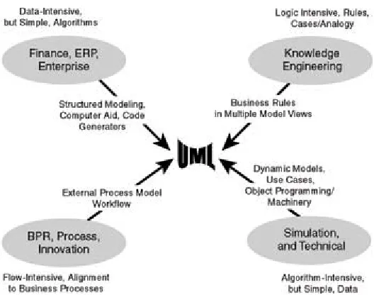
Figure 2-1. UML's smorgasbord - ingredients originating from several fields and appealing to a couple of fields each.
For example, when modeling a help desk for complex products, a traditional process model might show that each help-desk issue takes a carousel ride through the enterprise, visiting the desktops of various specialists until the issue is resolved. A structural approach, on the other hand, would stress call avoidance instead, using computers to execute frequently used knowhow to resolve issues automatically, passing only exceptions to the human- in-the-loop. In hi-tech industries, e-help desks are a good example of this
knowledge-oriented approach.[1] Case bases being its simplest kind, adaptive technology combines with the Web into an extremely powerful tool of business automation. Where feedback of know-how from new real-world cases is provided by thousands of web users, the system's capability to resolve new kinds of daily business problems will follow a steep learning curve, most often keeping the whole support process a simple man-machine dialogue in a semi-natural language.
With the process approach, two kinds[2] of business process models can be provided in the UML:
Activity diagrams
Business use cases, an extension to UML
[1]For an example of a case-based automated help desk, see Ask Iris
Online.™ Ask a question, in plain English, and Iris will try to answer it using a Toshiba knowledge base. www.csd.toshiba.com
[2]You might want to investigate other alternatives further:
Other process-flow notations (Catalyst, FirstSTEP, and so forth). The Workflow Management Coalition also has a cross-tool standard Process Definition Language. PC-tools are around, some of them supporting process simulation, what-if questions, and various
resource-utilization/product/efficiency analyses.
T. Winograd's Action-Workflow approach, top-down cycle-style.
[image:21.612.82.346.69.277.2]Using UML Activity Diagrams
Like other process-flow approaches, UML activity diagrams show the complete chain of activities for a single process. When there are many processes, we recommend that the activity diagrams be complemented by some kind of a graphical index of processes, for example, a simple, top-down process hierarchy chart or a simple business use-case diagram.
Strengths
This process-flow modeling technique fits long/complex back-office process chains, where other systems might be involved in addition to our system-to-be and sometimes also interleaved with manual activities. If that sounds like your project, then modeling the business process flows is what we
recommend. Existing organization and software is often put in question and reshaped as a result of this process analysis.
Limitations
Activity diagrams are usually less suited for knowledge-intensive activities, however, where flows are a perfect solution for the wrong problem. They are also less suited for front-office (e-) activities where the customer clicks/jumps more freely across processes, thereby turning our business process
redesign into event-driven dialogue design, whether we like it or not.
Because a picture is worth a thousand words, we have shown several examples of business process models using UML-activity diagrams:
1. Drinking in Florida
2. Drinking in Prague
3. Drinking in Stockholm
4. Drinking in 2080
Drinking in Florida
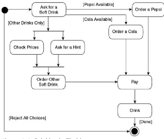
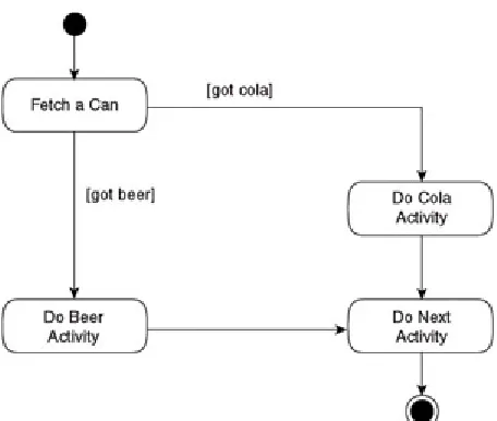
Figure 2-2 shows the basic thirst-slaking process for any business intending to stay in the sun, for example, Florida.
With the variety of paths offered under a variety of circumstances
[conditions], the benefits of diagramming the flow become visible. The icons in an activity diagram are simply activities performed by people, machines, or both. Most often, we focus on activities and postpone (or skip) issues like who will be doing what (see the box on p. 18).
As you can see in Figure 2-2, an activity can even have multiple exits, labeled by [conditions] (see Ask for a Soft Drink). It can have multiple entries, interpreted in an OR manner: the activity is simply triggered, no matter which way it has been currently entered, as is the case with Pay. Conditional paths might even be shown explicitly by decision nodes (see the box on p. 20).
The horizontal bars, called synchronization bars, start and end parallel activities, which is a major point in any process redesign. For example, to improve lead time, we either remove an activity or choose to perform it in parallel with other activities.
wallpaper-sized sketch, so we usually skip it.
Figure 2-2. Drinking in Florida
Drinking in Prague
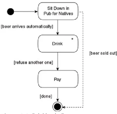
Figure 2-3 shows a thirst-slaking business process in Prague where 'one XL size fits all.'
In Prague, for the last thousand years or so, native pub customers have always expected only beer.[3] This has resulted in a remarkably simple work- flow. In some pubs for locals, taking a seat makes an appropriate number of pints (half-liters) emerge automatically on the guests' table, without an explicit order - a true management-by-exception style. You drink the beers placed before you, and then, in time refuse any more beers. No explicit order occurs because entering the pub (a business event[4]) translates into an implicit one.
Figure 2-3 shows that where an activity is entered once and repeated many times, it is modeled as one icon with an asterisk symbol (as is the case with Drink), and then terminated by an arrow with a condition saying something like [Refuse another one] or [No more left].
Swim Lanes
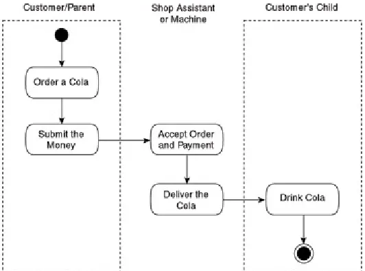
Where 'who does what' is important, some projects prefer a layout consisting of several parallel swim-lane partitions within each activity diagram (see Figure B2-1). Lines show the lane boundaries - with one department, person/role, or software component responsible for each lane. This adds the dimension of responsibility and exposes 'hand overs' between different groups, which often causes process problems.[*] Most UML tools support lanes.
[image:23.612.81.343.82.303.2]specified and designed down the road. Processes are horizontal and cross-department, so process redesign typically postpones the issue of responsibility. The typical course of steps here is customer
value/process objective - order of activities - responsibility. Also, all these steps show how important it is for the business experts and the process owners to become closely involved at this stage.
[image:24.612.99.365.139.337.2]
Figure B2-1. Swim lanes. With thirsty children or teenagers, a cola-order process can be partitioned into three swim lanes, showing each responsibility partition.
Here, the management-by-exception style leads to a greatly simplified business process. This process simplification is common in full-scale projects as well. Flow models, such as activity diagrams, tend to evolve into rather simple ones as a result of process redesign - as some activities become superfluous, some are merged, and some are automated. This example also illustrates another common problem, however, as extreme process-optimization introduces the risk of tunnel vision, translating into long-term costs somewhere else. In this example, the long-term costs are certainly transferred to the health care sector.
As you can tell from the [Beer sold out] condition, modeling rare error handling isn't relevant because those can be taken care of manually, along- side/outside this process. For the first version of an activity diagram - and of any dynamic model - make sure to target only mainstream scenarios, that is, the basic course, the happy path, the golden case, and so forth. Where necessary at all, extra detail is introduced in the next version. Here, we made such an addition, marking it as a dotted line. In our experience, such additions emerge from security and control issues, rather than from the primary objective of the process.
Figure 2-3. Drinking in Prague.
Diamonds Might Not Be Your Best Friend!
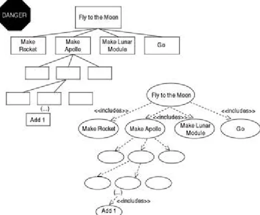
UML even allows diagrams showing decisions as explicit nodes (empty diamond icons) (see Figure B2-2). But, in practice these lead to lengthy discussions on gray-zone decision activities. For example, a decision step that includes work, like searching for and fetching the things to be decided on, such as beverages, is an activity and needs to be described as such. Therefore, if a project is pedantic on decision nodes, the size of the diagram tends to double. Remember, the meaning of the model is exactly the same even without the explicit decision nodes, that is, with arrows drawn directly from the preceding activity icon.
Clutter (rather than glitter) in the diagram is the smaller problem. The bigger problem is the time spent discussing those gray-zone steps that some team members view as an activity and others see as a decision. That's why we skip the diamonds in Figure B2-3.
[image:25.612.81.282.71.267.2]
Figure B2-2. Decision nodes separated. All that glitters is not
[image:25.612.99.365.483.654.2]
Figure B2-3. Decision nodes implied due to guard conditions. The meaning of both diagrams in this box is the same.
[image:26.612.84.287.428.685.2]Drinking in Stockholm
Figure 2-4 shows a future thirst-slaking process demanded in the past by some humoristic students in Stockholm.[5] Suppose the customers are being connected directly to the brewery, then the complex flow of process steps is replaced by the rather literal flow of liquid to the customer.
Figure 2-4. Drinking in Stockholm. The flow of process steps has been replaced by a literal flow of liquid to the customer.
limitation of activity diagrams and flow models. With a high degree of automation and self service, lengthy work flows collapse into only an activity or three. So, as the activity-diagram exercise nears completion, the diagram itself tends to disappear.[6] Ideally, the process modeling might deliver an almost-empty diagram of the process-to-be, replacing a wallpaper-sized process-as-is, and resulting in some jokes about what management consultants are paid for. However, this is a logical consequence of the objective to accomplish more by less ('less is more').
The Dangerous Waits
In a flow model, like an activity diagram, it's practical to indicate waits
because challenging them is the point of the whole exercise. If an insurance policy, for example, takes four weeks to complete, while total active time, with our insurance people working on it, is only four minutes, then we obviously need a new, more straightforward business process. If we're in luck, we get rid of the wait in the final process version. If we're unlucky - as the cause of the wait might be beyond our control - we mark it visually, to target it in the future.
Furthermore, by examining these wait points and asking 'what happens if the expected event doesn't happen?' usually uncovers new
functionality and requirements for the planned solution. In our insurance example, an obvious question is 'what happens if the policy isn't
completed in time?' Are there penalties? is it no longer legal? can we sue someone? are customer claims valid? and so forth.
Business automation also results in increased complexity within the system. This is prevalent when attempting to model processes involving customers' use of the Web. Web-based knowledge processing offers a shift from zigzag work flows to a one-stop shop that makes the process model look rather brief. This is caused by complex business logic - recently performed by people - moving from the outside to the inside of the system and, thus, turning business complexity into system complexity which needs to be modeled in other kinds of UML diagrams. Remember, the complexity is still there, except for some redundant activities being eliminated, but now, it's encapsulated within the future system.
Drinking in 2080
Imagine a new company called Wet-Liquids.com that delivers drinks to subscribers in smart houses in the year 2080 - a future thirst-slaking business. E-beer/e-cola can be downloaded on request to registered drinkers with payment made against drinks consumed. If this sounds too futuristic, then think of download-on-demand books or music instead, where this distribution channel is already being used. Otherwise, just suppose our firm of 2080 has several e-brewing patents pending that connect the Net to water pipes, applying a kind of telecom package-switching technology to liquids.[7]
Old, semi-manual work flows have disappeared because of extensive automation. Business process logic has become system logic, which simplifies our business model and makes activity diagrams less useful. We need another way to express the business view. This is when Jacobson's
business use-case diagrams are more appropriate for specifying requirements for such highly automated systems.
products was practiced centuries ahead of the current global trademarks and brand marketing!
[4]You'll discuss events often when producing activity diagrams. They are the
key triggers to all main processes.
[*]With parallel workflows, the communication between the threads is more
restricted in the UML than what is common elsewhere in 'flow' style diagrams.
[5]A practical joke by a couple of students at The Royal Institute of
Technology in Stockholm, Sweden, was the purchase of only one stock share in Stockholm's largest brewery. Since then, they've attended every annual meeting of shareholders, proposing repeatedly a large pipeline
across the city to connect the brewery directly to the school (a 'major customer to-be').
[6]This is a simple order-process example, but a high degree of automation
has also been tested with knowledge technologies in other processes. For example, the brewing process in North America, by Beck's Brewery
(www.becks.de).
[7]According to some European newspapers, The Coca-Cola Company is
Using Business Use-Case Diagrams
Business use-case diagrams emphasize value added and roles, called business actors and business workers, thus sharing some strengths and limitations with use cases (see Chapter 3). Generally speaking, a use case can be explained in detail in a description of the sequence of activities. For example: customer selects type of drink, system checks if valid request (depends on subscription and type of drink), system either dispenses drink or refuses request. If the sequence is too complicated and involves waits, and so forth, then an activity diagram offers more expressive power than a business use case.
Strengths
Business use cases typically fit front office (e-) activities with external inter- actions where external business actors, such as customers or suppliers, tend to skip across processes as they want. Where this is the case, we might need to structure the dependencies between processes, sometimes
borrowing even standard use-case relationships from the next chapter.
When published several years ago, business use cases met much less enthusiasm than Ivar Jacobson's use cases did in general. Customers were modeled as end users of a business, but this user relationship becomes rather literal as businesses make web sites their front offices. A new niche for the technique is thus emerging from a gray zone between traditional business modeling and standard use cases.
Limitations
This technique alone doesn't visualize long back-office style process chains. If these seem important to our project, we stress business process flows and we use activity diagrams.
Also, in a knowledge-intensive business, this technique is a starting point - not the point. Under such circumstances, we have to express business rules and constraints early or derive them by information-mining techniques, such as rule induction, or capture real cases in a case base. In businesses with high knowledge content, standard mainstream modeling tends to solve peripheral problems and avoid facing the challenge of describing the knowledge itself.
Figure 2-5 shows the four business use cases for Wet-Liquids.com. Each use case corresponds to a business process that might develop into a larger system use-case structure. This can even work without an activity diagram - as all activities are moved into our e-business system. This is an example of the gray zone between business-process modeling and standard use cases. Here, the technique is accepted as natural by most people.
In Figure 2-5, a business actor called 'Customer' (stick person icon) participates directly in one business use case at a time, maybe using a graphical menu.[8] Use-case icons with a slanting line denote the business
Figure 2-5. Drinking in 2080.
With this kind of dialogue structures and interdependencies, use-case modeling (the next step is covered in Chapter 3) is a practical technique in the dialogue with analysts or system designers.
[8]Even in the past, however, with customers typically serviced by
[image:30.612.82.307.71.245.2]But What About the Data?
We have several reasons to keep data modeling short in this lightweight book. As we explain in Chapter 7, data modeling is a technique suitable later on in the development process and, in addition, it has been covered
thoroughly for decades.[9] Also, in UML, we typically model both information
and what the system will be doing with it. This is shown in the structural view (see Chapter 4).
[9]However, at this stage (the process model), some people list the assets
Summary
Unsurprisingly, when aligning to business, we start with a business model, consisting of up to three views:
The process-flow view. UML activity diagrams mirror the course of activities in a flow, stressing the structure of a particular process. As the process innovation or automation exercise nears completion, they might collapse to near zero.
The e-view. Business use-case diagrams mirror a set of (sometimes automated) procedures, some of which can be shown in detail in activity diagrams. As the focus is on several processes, they can be useful where e-customers use the business in an ad-hoc manner, frequently crossing process boundaries. In most methodologies, we continue from business use cases into standard (system) use cases (see Chapter 3).
Chapter 3:
Adding Rigor to the
Requirements
Business modeling concerns process owners, reengineers, or business analysts with IT specialists in an advisory role. Later, in class modeling and especially in object interaction modeling, IT people become the driving force. Here, in adding rigor to the requirements through use-case modeling, there's a shared effort. Business experts provide the essence of the requirements, while IT specialists provide the structure. Having modeled the business, we now start aligning the system specification - most of it being the functional requirements - to the requirements of our business processes.
A diagram technique for this is very widespread: UML standard use cases that were pioneered some 20 years ago by Ivar Jacobson. Use cases are simply the ways in which the actors use the system. A similar step is natural in any knowledge industry because exact requirements minimize lead time and misunderstandings.
Use Cases
Human-computer interaction (HCI) is a vast field, to which use cases contribute with a practical, down-to-earth technique for the doers. To end users of the planned solution, the user interface often seems to be the entire system. Use cases extend this simplified view by modeling what's going to happen at the user interface, as well as interfaces to other systems. Use cases, interface layout examples, and prototypes complement each other, so they fully define the functional requirements of the system. Any remaining UML diagrams specify the inside/kernel of the system hidden behind that inter- face. The expectations to be met are similar in all three of the use cases, layouts, and prototypes:
Users need to rely on/feel comfortable with the system.
The HCI feels easy, yet not boring, and it matches both common standards and the user's view of the business activity.
Sometimes, one use case can involve multiple forms of user interface. For example, in a management game, all these kinds of views might be available in parallel, as separate windows or as several partitions of the same window in a use case like 'Your next move.' For example, the views may include a world map, 3-D movie shots, diagrams of results, and a control panel with sliders for allocating/increasing/decreasing investment to various areas. Also, a web-dialogue use case, such as e-purchase, can span four or five form pages in only one use case, which isn't completed until the last page has been successfully submitted into the system.
Functional requirements are expressed in this UML use-case model,
whereas the nonfunctional requirements are recorded in supplementary text, such as separate e-documents,[1] or as footnotes to UML documents.
Requirement elicitation takes considerable cooperation in brainstorming, workshops, interviews, storyboarding, and prototype evaluation. Use cases work fine as long as you use them to specify functionality as external interactions in the right place: the system boundary. This takes some experience and common sense, so we provide 'warnings' toward the end of this chapter.
Strengths
requirements clear, including their interdependencies. This provides an answer to the challenge of many, complex, or important external
interactions. For example, those for mobile phones, switching, booking, or incoming orders. Use cases simplify some additional activities, such as project management, mentioned in the section 'Use-Case Example.'
Limitations
Sophisticated systems hide a complex interior behind a surprisingly simple exterior. For example, on icy roads, drivers don't expect a complex user dialogue from antiskid systems and stabilizers, but they do expect stability and survival to be delivered automatically. With knowledge systems, data warehouse, or data mining, standard use cases can only provide a sketchy starting point, rather than the expected hints about our system-to-be. Sometimes these starting points are as simple as Start, Stop, Repeat. Furthermore, in complex agent/batch processing, systems often behave like (human) actors: rather than being driven by external interactions, they can be self-driven by internally generated events. In all similar cases, you need to specify the structure of your system-to-be early on in the project to get a realistic picture.
Why do we have rather general expressions like 'actors' and 'use cases'? One reason is the practical convenience of a brief, well-defined term. An
actor covers both 'a person like a user or system administrator' and 'an external system interacting with our system-to-be.' Similarly, a use case - 'a behaviorally related sequence of interactions, performed by an actor with the system' - covers a variety of external interactions, from a user dialogue to a stepwise handshake between two software systems without humans in the loop.
Before we start to identify the use cases, we list all actors supposed to be in touch with the system boundary. The list makes it easier to determine the use cases required by these actors. Jacobson's original Swedish term (aktör,
with a double-dot above the o) corresponds to 'actor' in a market-like context, rather than on stage. Typically, an actor has a well-defined role within a business and some of the actor's business activities become use cases in our system-to-be. For example, in a system specification for a theater, UML actors are payroll clerks, producers, marketing personnel, external travel agency systems, and so forth.[2] Any actor can be involved in a single use case, or several use cases, with or without other actors, as we can see in Figure 3-1.
[1]We use the term 'e-documents' throughout to indicate those documents
produced by the varieties of word processors and in various formats, including HTML.
Use-Case Example
In the business example for Drinking in 2080 in Chapter 2 (Figure 2-5), we saw business use cases for downloading drinks and providing some online support. As we look into the business use case called Request Support, the resulting use cases for the system (called system use cases) turn out to be web-customer dialogues, as shown in Figure 3-2. The core is a mainstream system use case, which is often outlined quite explicitly by the process-owner or reengineer.
Figure 3-1. A system use case can be related to several actors, as is the case in Pay Drink Account. An actor can be related to several use cases, as is the case with Web Customer.
From this mainstream system use case, others appear in the structure linked by use-case relationships (the dashed arrows in the diagram). These related use cases - let's call them mini-use cases - represent complementary activities that are either less usual or common interactions reappearing in other use cases. These mini-use cases and their relationships are usually modeled by the IT staff, so for other stakeholders in the project, the ability to read and understand the arrows will do.
In use-case relationships, the dashed arrows show the dependency and a «stereotype» denotes a variant (this time, a variant of that dependency). Thus, the «include» arrow between the use cases makes the mainstream use case always include the mini-use case, that is, it's dependent on that use case. To get online support on our Web site, customers must confirm product details. This mini-use case can now be shared by several
mainstream use cases, not only in support, but also in marketing or delivery planning. If this mini-use case were made part of the mainstream, then the result would be doubled maintenance in the future because changes to the product-confirmation mini-dialogue would be repeated in all those
mainstream use cases.
Generic Actors
UML also supports abstract (generic) actors,* such as 'someone doing the bookings' or 'customer contact personnel.' Although not widespread, this simplifies both vendor specifications for off-the-shelf software packages and enterprise systems that must be adjusted to many local branches. For example, if you intend to sell a booking and scheduling package to anyone from dentists to lawyers (as in Figure B3-1), the specification can't rely on actor definitions from a single sector of industry. Therefore, we prefer a few abstract actors to start with for the use cases, rather than an ever-growing list of 'real' actors.
You can even let a single ('abstract') stick figure generalize several roles in the same business as long as it's involved in the same dialogues.
Figure B3-1. An abstract actor represents several kinds of actors - often from several business units - all of these using the system in the same way and playing the same role in, for example, the booking dialogue. This technique comes in handy where appropriate, although it is seldom used.
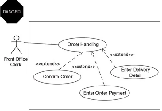
The «extend» arrow between use cases makes the mainstream use case pointed to sometimes extended by the one pointing to it. A condition will be stated later on, referring to an extension point stated under the horizontal line in the mainstream use case - for example, the extension point called
complexity. Another example:
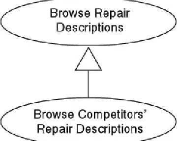
If a possible repair is found, the customer can browse the information and also view any relevant videos (another «extend»).
If no repair is found, then the advanced helper is used to assist in defining the problem.
Everyone needs some guidelines on reading the arrows here: unsurprisingly, we always read in an arrow's direction. Read the diagram once again if you want.[3] Thus, the «extend» arrows point the opposite way (to the
mainstream icon) because we parse them in their direction. Here. for example, we want the (rare) Launch Advanced Helper mini-use case to extend the mainstream one.