This is a repository copy of
An improved rotation-invariant thinning algorithm
.
White Rose Research Online URL for this paper:
http://eprints.whiterose.ac.uk/785/
Article:
Rockett, Peter (2005) An improved rotation-invariant thinning algorithm. IEEE
TRANSACTIONS ON PATTERN ANALYSIS AND MACHINE INTELLIGENCE, 27 (10). pp.
1671-1674. ISSN 0162-8828
https://doi.org/10.1109/TPAMI.2005.191
[email protected]
https://eprints.whiterose.ac.uk/
Reuse
Unless indicated otherwise, fulltext items are protected by copyright with all rights reserved. The copyright
exception in section 29 of the Copyright, Designs and Patents Act 1988 allows the making of a single copy
solely for the purpose of non-commercial research or private study within the limits of fair dealing. The
publisher or other rights-holder may allow further reproduction and re-use of this version - refer to the White
Rose Research Online record for this item. Where records identify the publisher as the copyright holder,
users can verify any specific terms of use on the publisher’s website.
Takedown
If you consider content in White Rose Research Online to be in breach of UK law, please notify us by
An Improved Rotation-Invariant
Thinning Algorithm
Peter I. Rockett
Abstract—Ahmed and Ward [2] have recently presented an elegant, rule-based rotation-invariant thinning algorithm to produce a single-pixel wide skeleton from a binary image. We show examples where this algorithm fails on two-pixel wide lines and propose a modified method which corrects this shortcoming based on graph connectivity.
Index Terms—Thinning, skeletonization, graph theory.
æ
1
I
NTRODUCTIONTHEthinning (or skeletonization) of segmented binary images is a much-used and well-studied topic in image processing and related fields. In a frequently cited review published in 1995, Lam and Suen [1] reviewed around 100 thinning algorithms and significant numbers of new algorithms have been proposed in the intervening years. Of recent note is the rotation-invariant thinning algorithm of Ahmed and Ward [2] which used the particularly elegant device of deriving a set of predicates over the 8-neighbors of a given pixel to determine if that pixel is on the boundary of a shape and can thus be deleted. As part of our present work, we have used the Ahmed-Ward (A-W) thinning algorithm to extract the center lines of arteries segmented from X-ray angiograms as a prelude to further proces-sing. These vascular trees are significantly more complex than any of the characters examined by Ahmed and Ward and, in the course of our work, we have observed a number of cases where the A-W algorithm fails to produce a center line of single pixel width. One such example is shown in the image fragment of Fig. 1, where the union of the black and white pixels represent the original shape and the white pixels show the center line produced by the A-W algorithm. Notice that a portion of this center line is a two pixel wide vertical line and seems to arise because the rules constructed by Ahmed and Ward to deal with two-pixel wide sections do not cover this (and some other) pixel configuration(s). We emphasize that the occur-rence of 2-pixel wide center lines is fairly rare—we typically observe between 2 and 5 in an angiogram image—but they are nonetheless undesirable. The existence of even one pathological case, however, constitutes a disproof of the A-W algorithm.
The A-W algorithm proceeds by deriving a set of rules over the 8-neighbors of the pixel which is a candidate for deletion. In its initial form, however, the algorithm cannot handle lines of two pixel width and, consequently, Ahmed and Ward added further rules to deal with two pixel wide lines which involved extending the window over which the deletion decision was computed to include the four blocks of three pixels immediately above, below, to the right and to the left of the original33region—20 pixels in all. (The four
corner pixels of this55region are “don’t care” cases.) Although
inducing a set of rules over the eight neighbors (256 possible configurations) has proven eminently tractable, producing a set of foolproof rules to handle two-pixel wide lines over the 20 pixel set (220
1 million possible configurations) is a formidable task and a few of the possible configurations, such the one in Fig. 1, are not dealt with correctly. The A-W rules for 2-pixel wide lines involve
examining the pixels in a43(or34) window and it is clear that
among other configurations, two-pixel wide sections which are only two pixels long (e.g., Fig. 1) are not properly handled.
In this paper, we propose a modification to the rotation-invariant thinning algorithm of Ahmed and Ward based on their set of 20 rules to carry out most of the thinning, thus preserving the property of invariance to rotation. To deal with the case of two-pixel wide lines, however, we use a different procedure, mindful of the origin of the shortcoming of the A-W algorithm set out in the preceding paragraph. We adopt a two-stage thinning procedure which uses the A-W rules to thin down to a skeleton whichincludes 2-pixel wide lines—we make no attempt to deal with this case in the first stage. As a second stage, we examine the 2-pixel wide lines in the provisional skeleton produced by the first processing stage to see which pixels, if any, can be deleted without compromising the connectivity of the skeleton.
In the following section, we describe our modified algorithm and present some results in Section 3. Finally, we offer some remarks and conclusions in Section 4.
2
D
ESCRIPTION OF THEM
ODIFIEDA
LGORITHMOur algorithm comprises two stages: First, we apply the 20 rules of Ahmed and Ward over the 8-neighbors of each pixel, in turn, to determine if that pixel is on the boundary of the shape to be thinned and hence can be deleted. Like the A-W algorithm, this first stage is applied iteratively where the pixels are marked for deletion if they are adjudged to be on the shape’s boundary and then all marked pixels are deleted at the end of an iterative pass. Again, like the A-W algorithm, we skip pixels which are found to be at the extrema of diagonal lines. Most importantly, any pixels which are found to be part of two-pixel wide vertical or horizontal lines, that is which fit any of the rules:½0 w 1 0,½0 1 w 0,½0 w 1 0T, or
0 1 w 0
½ T are skipped—two-pixel wide lines are processed in
the second stage. Similar to the A-W algorithm, the first stage progressively removes pixels from the boundary of a shape until the shape has been eroded to a skeleton ofmostlysingle pixel width.
The second processing stage takes the provisional skeleton from the first processing stage—where we know all the pixels, by definition, boundary pixels—and examines every pixel which makes up part of a two-pixel wide line. If deletion of such a pixel does not disrupt the connectivity of the skeleton, we remove it immediately from the skeleton in a single pass. Thus, at the end of this single pass, the skeleton comprises only single-pixel wide segments. If any two pixel wide blocks remain, these cannot be deleted without producing a disconnected skeleton.
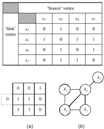
In order to efficiently determine if deletion of a pixel in a 2-pixel wide line will disrupt connectivity, we build an undirected graph of the local pixel connectivity over its eight neighbors. The process is illustrated by the example in Fig. 3 and Table 2, where the pixel labeling convention we have used is shown in Fig. 2.
Fig. 3a shows an initial pixel configuration in the provisional skeleton produced by the first thinning stage. Note that, for this example, we assume that the middle two pixels form part of a two-pixel wide vertical line as implied by the zero two-pixel shown dotted to the left. Fig. 3b shows the graph representation of the connectivity in the33region for the nonzero pixels of Fig. 3a where arcs represent
physical adjacencyof the (nonzero) pixels. For example,x1can only
connect tox2; x3; x7, andx8, assuming that the pixels at both ends of
an arc are “1.” In other words, an arc is only allowable if it is possible to pass from one pixel to the other without passing through a third pixel. A full list of allowable arcs is shown in Table 1.
From Fig. 3b, it is readily apparent that the central pixel in Fig. 3a (vertexx0) can be safely deleted without breaking the connectivity of
the skeleton sincex0can be removed from Fig. 3b leaving a subgraph
where every vertex has at least one arc connected to it. In order to implement this notion, we construct an adjacency matrix for the connectivity graph and examine the scenario where the central pixel is deleted. In fact, it is sufficient (and faster) to construct only the . The author is with the Department of Electronic & Electrical Engineering,
University of Sheffield, Mappin Street, Sheffield S1 3JD, UK. E-mail: [email protected].
Manuscript received 2 Nov. 2004; revised 28 Feb. 2005; accepted 2 Mar. 2005; published online 11 Aug. 2005.
Recommended for acceptance by P. Torr.
For information on obtaining reprints of this article, please send e-mail to: [email protected], and reference IEEECS Log Number TPAMI-0592-1104.
adjacency matrix for the subgraph resulting from excluding the central pixel. The adjacency matrix for the corresponding subgraph of the graph in Fig. 3b is shown in Table 2. From this table, it is clear that in order for the deletion of the central pixel not to create a disconnected skeleton, every row (or column) of the adjacency
matrix must contain at least one nonzero entry. The speed of searching the adjacency matrix can be improved by an “early jump-out” approach: When searching a row, as soon as the first nonzero entry is encountered, we can move on to searching the next row since the presence of a single “1” is enough to guarantee connectivity (for that row). Similarly, as soon as we find the first row that contains only zero entries, we can terminate the search since a single empty row tells us we cannot delete the central pixel under consideration. By way of counterexample, Fig. 4 shows a pixel configuration in the first-stage skeleton where the central pixel cannot be removed as evidenced by the fact that vertexx2will become disconnected if
vertex x0 is deleted. Deducing this conclusion from the
corre-sponding adjacency matrix is trivial.
In practice, constructing and searching the adjacency matrix is fast and efficient. Since we treat a33image patch and the central
pixel and at least one other pixel are set (in order to constitute a two pixel wide line), the adjacency matrix has to consider the connectivity of only the remaining seven pixels in the33patch. Since, at this
stage of the algorithm, we are dealing withexteriorpixels, strictly less than seven pixels can ever be set. As a consequence, the adjacency matrix is strictly smaller than77and, typically, much smaller than
even this. (In fact, we show below that the algorithm described here can be faster than the A-W algorithm.)
3
R
ESULTSFig. 5 shows the thinning results for the portion of X-ray angiogram image shown in Fig. 1 with the algorithm presented here and for which the A-W algorithm fails. Note that the algorithm described here does indeed produce a single-pixel wide skeleton although the overall skeletonization is (unsurprisingly) slightly different.
Figs. 6 and 7 contain two more examples of pixel configurations taken from X-ray angiograms for which the A-W algorithm fails to produce a single-pixel wide skeleton. Both Figs. 6a and 7a show the results of the A-W algorithms and in Figs. 6b and 7b, the results obtained here. Again, the skeleton obtained from the new algorithm is of the desired single-pixel width.
[image:3.612.103.198.70.193.2]In addition to the examples taken from the complex vascular trees obtained from X-ray angiograms, Figs. 8 and 9 compare the A-W and present algorithms for the task of skeletonizing two
[image:3.612.328.501.95.311.2]Fig. 1. A fragment of a segmented X-ray angiogram illustrating the breakdown of the Ahmed and Ward [2] thinning algorithm. The union of the black and white pixels is the original shape to be thinned and the white pixels show the final center line produced by the Ahmed-Ward algorithm. Note the22block in the center of the image.
Fig. 2. The pixel numbering convention used here. (This is identical to Ahmed and Ward [2] except that we extend their notation to label the central pixel asx0.)
[image:3.612.113.191.245.326.2]Fig. 3. Example of construction of an undirected connectivity graph. (a) Shows the original pixel configuration and (b) the resulting graph.
TABLE 1 Allowable Arcs
Note that the vertices at both ends of an arc must be “1” ( or true).
TABLE 2
Adjacency Matrix for the Graph Shown in Fig. 3b
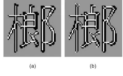
[image:3.612.55.253.357.470.2] [image:3.612.83.223.516.688.2]Chinese characters taken from Lin and Chen [3] and which have also been used by Ahmed and Ward [2]. Although the both algorithms yield acceptable, single-pixel wide skeletons for these characters, the skeletons obtained are slightly different in nature. Since there is no established method for objectively comparing thinning algorithms, we confine ourselves to subjective observations based on the examples of the angiogram images and the Chinese characters in Figs. 8 and 9.
First, whereas the A-W algorithm often tends to skeletonize diagonal lines with a “staircase” structure comprising two hor-izontal pixels followed by two vertical pixels, the modified algorithm presented here tends to produce diagonal runs of pixels connected NW-to-SE (or NE-to-SW). Thus, the new algorithm arguably achieves a greaterdegreeof thinning in that the resulting skeletons are more generally made-up of single-pixels rather than “staircases” of two-pixel long “risers” and “treads.”
Second, the A-W method appears to be more aggressive in eroding the ends of lines than the new algorithm; this is particularly evident from the Chinese character results. Whether this is an advantage or not probably depends on the end-application for the skeleton. Certainly, for our work on X-ray angiograms, the present thinning algorithm is preferable since we are interested, among other things, in identifying the end points of terminal capillaries in arterial networks.
The numbers of pixels comprising the final skeletons of the Chinese characters for each algorithm are shown in Table 3. There appears to be no great difference in the overall numbers although the new algorithm tends to use fewer pixels in the interior of skeleton segments and rather more at the ends of strokes.
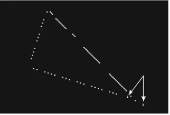
We have also examined the operation of our modified algorithm on the sequence of rotated symbols used by Ahmed and Ward [2, Fig. 3b]. Since the basis of our modified algorithm is the A-W rule set, the modified algorithm produce results which differ only in its treatment of diagonal lines. These differences can be conveniently summarized by the results of thinning the triangular shape (from the third column in A-W’s Fig. 3b) and are shown in Fig. 10.
The original A-W algorithm thins diagonal segments down to the “staircase” structures described above whereas our algorithm makes greater use of diagonal connectivities to produce a smoother skeleton. The difference between Figs. 10a and 10b are shown in Fig. 11 where the pixels which are present in the A-W result (Fig. 10a) but absent from the results of the modified algorithm (Fig. 10b) are shown in white. This difference illustrates that the modified algorithm tends to use fewer pixels in generating a skeleton from a diagonal segment. Similarly, the two pixels which are present in Fig. 10b, but absent from Fig. 10a are arrowed; the fact that these two pixels are both next to pixels used by the A-W algorithm indicates that the modified algorithm is simply making an alternative choice of skeleton pixel in these cases.
As to the relative execution times, we have compared the average run times over 10 executions for a928342X-ray angiogram image
[image:4.612.103.201.71.192.2]and the new algorithm runs ~ 6 percent faster (234mSversus219mS) since there are fewer rules to be evaluated in the iterative phase of the
[image:4.612.316.516.71.194.2]Fig. 5. Result of thinning for the section of X-ray angiogram image shown in Fig. 1 using the present algorithm. The final skeleton is shown with the white pixels.
[image:4.612.313.512.221.344.2]Fig. 6. A second example of thinning for a section of an X-ray angiogram image. (a) Shows the skeleton obtained with the A-W algorithm and (b) that obtained with the present algorithm. The final skeletons are shown with the white pixels.
Fig. 7. A third example of thinning for a section of an X-ray angiogram image. (a) Shows the skeleton obtained with the A-W algorithm and (b) that obtained with the present algorithm. The final skeletons are shown with the white pixels.
Fig. 8. Skeletonization of a Chinese character using (a) the A-W algorithm and (b) the present algorithm.
[image:4.612.48.259.222.339.2]Fig. 9. Skeletonization of a Chinese character using (a) the A-W algorithm and (b) the present algorithm.
TABLE 3
[image:4.612.48.257.365.472.2] [image:4.612.323.505.400.456.2]new algorithm. By contrast, when comparing the execution times of both algorithms on Ahmed and Ward’s Fig. 3, the algorithm presented here ran ~18 percent slower than the A-W algorithm due to the large number of diagonal segments present in this image and, hence, the extensive application of the graph-based thinning stage. For yet other images, the execution times of the two algorithms were indistinguishable. In general, therefore, it appears that the comparative execution times are similar but detailed differences depend on the particular image under consideration. Both algo-rithms required the same number of iterations of applying the thinning rule set.
4
D
ISCUSSIONS ANDC
ONCLUSIONSThe principal contribution of this work is to remedy a deficiency in the thinning algorithm of Ahmed and Ward [2] by modifying the way in which lines of two-pixels width are handled. We have shown that a few pathological configurations exist for which the A-W algorithm does not produce single-pixel wide lines. Rather than attempting to thin two-pixel wide lines using an extension of the rule-based methodology of Ahmed and Ward which requires characterization of a window encompassing more than the eight neighbors of the pixel under consideration, we have used a two-stage process whereby we utilize Ahmed and Ward’s thinning rules to produce a provisional skeleton containing two-pixel wide segments which are then subsequently thinned where possible in a single pass of a second stage. This second stage uses a graph-based method of determining whether a pixel in a two-pixel wide line can be deleted without disrupting the connectivity of the skeleton. The new algorithm produces results which are qualitatively different from the A-W algorithm despite both sharing a common set of thinning rules. In addition to arguably achieving what seems to be a greater degree of thinning than the A-W algorithm, the new
algorithm appears to effect far less aggressive erosion of the ends of lines. Since the new algorithm utilizes the rotation-invariant thinning rules of Ahmed and Ward, the skeletons it produces will possess the same rotation invariant properties as skeletons produced by the Ahmed-Ward algorithm although the claim of rotation invariance needs to treated somewhat carefully. For a two-pixel wide line, the skeleton is considered as running between the two pixels and which of the two is deleted to yield a single-pixel wide center line is completely arbitrary. Ahmed and Ward chose the bottom-most pixel in a horizontal 2-pixel line and the right-most in a 2-pixel vertical line. Here, wetendto delete the top-most and left-most pixels although this choice is implementation-dependent and determined by the scan order (from top-left) in the second stage of the algorithm; this could trivially be reversed to follow the same choice as Ahmed and Ward by scanning from the bottom-right. Nonetheless, since the choice of which pixel to delete from a 2-pixel wide line is arbitrary and implementation-dependent, no thinning algorithm can betrulyrotation invariant. To select a consistent pixel to delete, independent of rotation would require recognition of the shape’s pose and, therefore, recognition of the shape. But as one of the main uses of skeletonization is recognition, using knowledge of the shape’s pose to guide the thinning process is, in most cases, a paradox.
A
CKNOWLEDGMENTSThis work was supported by the UK Joint BBSRC/EPSRC/MRC Discipline Hopping Programme under Grant No. GR0300594. The author is also grateful to Maher Ahmed and Rabab Ward for kindly providing copies of the images used in their paper for comparison purposes.
R
EFERENCES[1] L. Lam and C.Y. Suen, “An Evaluation of Parallel Thinning Algorithms for Character-Recognition,”IEEE Trans. Pattern Analysis and Machine Intelli-gence,vol. 17, no. 9, pp. 914-919, Sept. 1995.
[2] M. Ahmed and R. Ward, “A Rotation Invariant Rule-Based Thinning Algorithm for Character Recognition,”IEEE Trans. Pattern Analysis and Machine Intelligence,vol. 24, no. 12, pp. 1672-1678, Dec. 2002.
[3] J.Y. Lin and Z.A. Chen, “Chinese Character Thinning Algorithm-Based on Global Features and Contour Information,”Pattern Recognition, vol. 28, no. 4, pp. 493-512, Apr. 1995.
[image:5.612.104.464.71.214.2].For more information on this or any other computing topic, please visit our Digital Library atwww.computer.org/publications/dlib.
Fig. 10. Results of thinning a representative triangle form Fig. 3b of Ahmed and Ward. (a) Shows the result from the A-W algorithm whereas (b) shows the result from the present algorithm.
[image:5.612.66.240.606.724.2]