iii
“I admit that this report is my own work except every such summaries and quotations
that I have cited."
Signature : ………
iv
"I declare that I have read this work and I believe this work have fulfill the scope and quality for the award of Bachelor of Electronic Engineering (Industrial Electronics)."
Signature : ……….
Supervisor Name : ……….
v
This thesis is dedicated to my beloved parents, Salim Bin Abu and Jamni Binti Omar, for
vi
ACKNOWLEDGEMENT
To God be the glory, for great things He has done, to allow me health to finish this Final Year Project. First and foremost, I would like to thank my parents for their love and support throughout my life. Thank you for giving me strength to chase my dreams. My sisters and brother deserve my wholehearted thank as well for their support in emotional and financial aspect.
I would like to sincerely thank my supervisor, Madam Maizatul Alice Meor Said, for her guidance and support throughout this Final Year Project and especially for her confident in me.
Finally, to all my friends, thank you for your understanding and encouragement
vii
ABSTRACT
This project is about GSM Based Display Toolkit that works as a security alarm system. There are several reasons that lead to the existing of this project, which are the alarm systems that exist today not efficient enough in term of information transfer. The
viii
ABSTRAK
Projek ini adalah mengenai “GSM Based Display Toolkit” yang dikhususkan
untuk sistem keselamatan. Terdapat pelbagai masalah yang menyebabkan produk ini terhasil. Objektif kajian kami adalah untuk menghantar pesanan ringkas kepada pemilik produk ini seandainya sensor yang digunakan mengesan penceroboh memasuki kawasan pemilik. Bukan itu sahaja, kajian ini juga adalah untuk memaparkan amaran melalui LCD. Dengan hal ini, iaitu menghantar pesanan ringkas dan memaparkan amaran tersebut melalui LCD, kajian ini dapat menghasilkan satu produk keselamatan yang lebih efektif dalam menangani masalah jenayah. Untuk membolehkan sistem ini berkerje seperti yang dimahukan, terdapat beberapa perkara yang perlu dikaji seperti prinsip kerja
ix
CONTENTS
CHAPTER ITEMS PAGE
PROJECT TITLE i
DECLARATION iii
DEDICATION v
ACKNOWLEDGEMENT vi
ABSTRACK vii
ABSTRAK viii
CONTENT ix
LIST OF FIGURE xii
LIST OF TABLE xiv
LIST OF APPENDIX xv
1 INTRODUCTION 1
1.0. INTRODUCTION 1
1.1. OBJECTIVE 5
1.2. PROBLEM STATEMENT 6
x
1.4. METHODOLOGY 9
2 BACKGROUND STUDY 11
2.0. PIC16F877A 12
2.1. GSM MODEM 13
2.2. MAX232 15
2.3. REED SENSOR 18
2.4. LIQUID-CRYSTAL DISPLAY 20
2.5. CCS COMPILER 23
2.6. PROTEUS 7 PROFESSIONAL 24
3 METHODOLOGY 27
3.1. INTRODUCTION 27
3.2. BLOCK DIAGRAM 32
3.3. PROJECT MODEL 33
3.4. WORKING PRINCIPLE 34
4 RESULT AND DISCUSSION 35
4.0. CIRCUIT SIMULATION 35
4.1. CIRCUIT LAYOUT 43
xi
4.3. COMPONENT INSTALLATION &
TESTING 45
5 CONCLUSION AND SUGGESTION 49
5.0. CONCLUSION 50
5.1. SUGGESTION 51
REFERENCES 53
APPENDIX A 56
xii
LIST OF FIGURE
NO TITLE PAGE
1.0 Block Diagram of the Project 3
1.1 Magnetic Switch 4
1.2 Design of the Project 8
1.3 Basic Project Flowchart 9
2.0 PIC16F877A Pin Diagram 12
2.1 GSM Modem 13
2.2 MAX232 Pin Diagram 15
2.3 Basic Connection of MAX232 17
2.4 Male and Female DB9 Connector 17
2.5 Reed Sensor 19
2.6 Reed Sensor Actuated by Magnet 19
2.7 Implemented Reed Sensor 20
2.8 LCD 16x2 Display 21
2.9 Pin Diagram of 16x2 LCD Display 22
2.10 CCS Compiler 23
2.11 CCS Compiler Workspace 23
xiii
2.13 ISIS Workspace 25
2.14 ARES Workspace 26
3.0 Program Flowchart 28
3.1 Project Flowchart 29
3.2 Project Block Diagram 32
3.3 Project Model 33
3.4 Basic Function of Project 34
4.0 Supply Voltage for PIC16F877A 36
4.1 Connection of Reset Button 37
4.2 Connection of MAX232 with PIC 37
4.3 LCD Connection 38
4.4 System On 39
4.5 Both Switches closed 40
4.6 Switch 1 is Open 41
4.7 Switch 2 is Open 42
4.8 Main PCB Layout 43
4.9 LCD Layout 44
4.10 Main Circuit after Etching Process 45
4.11 Circuit Installation 46
4.12 LCD Display “Welcome” Sign 46
4.13 Message from GSM Modem 46
4.14 LCD Display when Sensor Triggered 47
4.15 Message when Switch 1 Triggered 47
4.16 Message when Switch 2 Triggered 48
xiv
LIST OF TABLE
NO TITLE PAGE
2.0 LED Indicator for GSM Modem 14
2.1 Set of AT-Command 15
2.2 Capacitor value for Different Device 16
2.3 Pin Representation for DB9 Connector 18
xv
LIST OF APPENDIX
NO TITLE PAGE
A MAIN PROGRAM CODE 56
CHAPTER 1
INTRODUCTION
1.0. Introduction
In a situation where there is high level of thief, there is need for better security system [1]. There is a growing interest in intelligent home network as a way to offer a comfortable, convenient and safe environment for occupants. In order to enhance the occupants convenient and safety, home security system is important in the field of intelligent home network. The requirements of a home security system include low cost, low power consumption, easy installation and rapid response to alarm incident [3].
2
wireless technology has some remarkable benefit comparing with non-wireless technology. Research shows that Bluetooth, Zigbee, 802.11 and wireless USB are the most popular technology in the field of wireless network. However, the technology that has been mentioned is high in power consumption, high in cost and don’t present the implementation.
Is has become more crucial to inform the user in real-time when the alarm is triggered. Other than the technology that mentioned earlier, it also can be done via internet or GSM/GPRS. However, GSM is more convenient than the internet. The main reason why the GSM is more convenient is that the GSM network has wide spread coverage, making the whole system available for almost all the time,
since GSM is stand for Global System for Mobile Communication. Furthermore, GSM network has high security infrastructure which make sure that the information sent/receive cannot be monitored.
3
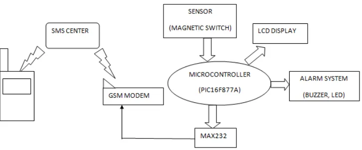
Figure 1.0: Block Diagram of the Project
GSM is a digital mobile phone system, operating in several frequency bands. Most knowing bands are 900MHz, frequencies, 1800MHz but also in the bands of 1900MHz and 2100MHz depends on their memory cards called SIM (Subscriber Identity Module), which provide user identity to network with their telephone number assign [2]. GSM provide the highest quality data calls, and moreover, offer the possibility of using the same mobile phone (with the same SIM card, and hence the same number) and other network around the world
(roaming) so that the user can be found even if it is not in the country. The GSM itself consist of the interconnected cell. Each cell corresponds to a specific antenna (base station), placed on towers or tall building to avoid a near-immediate access to their public persons.
4
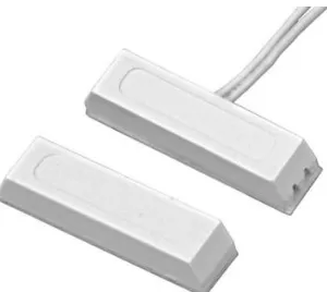
To detect any activity such as open door/window, the reed sensor is used. This project will help the alarm systems exist today more efficient since the user/owner can get the notification immediately as the reed sensor is triggered simultaneously with LCD display by the microprocessor. Not only that, by display the warning signal using the LCD display, people surrounding will notice immediately which house/premise has an intruder. This is the important of this project which it is affordable to most people. People will not only can hear, but also can see the warning signal. This is the adding value of this product because it helps people with hearing problem to contribute/take action when he/she are at the incident site.
After some research, the reed sensor is the best sensor that can be used for this project. There are many sensors that can be used such as PIR sensor, but research finding that reed sensor is more suitable since it can act as a switch. This magnetic switch is employed as magnet-sensitive contactless bi-stable limit
[image:19.612.273.423.440.574.2]switch. More about this sensor will be discuss in Chapter 3.
5
1.1. Objective
The aim of this project is;
i. To send the notification to the owner.
It becomes more crucial to inform the user in real-time when the alarm system is triggered. By using the GSM modem, the notification /message can be sent to the user when the alarm system is triggered. When the sensor detects the intruder/theft, it sends the data to the processor to process information, and send message to the owner via GSM modem. User will get the message through the phone.
ii. To display the warning signal
The adding value on this product is the LCD display. This will make people more aware about the current incident. Not only that, people with
hearing problems can also react with the situation because she/he can see the warning signal from the LCD. This product will not only send the message to the user, the warning signal also is displayed through the LCD display. This LCD display is placed at outside of the premise/home. By display it, the people at surrounding can see easily where that sign is come from. So the information can transfer smoothly.
iii. To make the security alarm more efficient.
6
1.2. Problem Statement
The security systems nowadays are too expensive to most people that have middle income. Research find that for ADT alarm, the moderate cost is around RM900.00 and above. Next, security alarm that exists also can’t make the people on surrounding to be aware to that warning sound. People sometimes would get confused to detect the exact location of that warning sound. Not only that, in real world, when the alarm system is triggered, people will automatically assume that the alarm system is broken or is being fixed by the user. At this point, it can be seen the alarm system that exist today not efficient in term of information transfer. The most important things is, today alarm system failed to
inform the owner about the incident. Try to guess what happen when the alarm system is triggered at midnight? There will be no people surrounding to react with the situation. This problem becomes more serious when come to public holiday, such as Hari Raya where most of people will back to their hometown for a several days. The user will not notice it until the time he/she come to premise/home. This make the alarm system is not efficient enough.
Therefore, to overcome these problems, GSM Based Display Toolkit: Alarm systems are introduced. These systems will give the notification message to the owner immediately once the alarm is triggered. Not only that, it also will display the warning signal at the LCD display so that people around will notice it immediately. By display the warning signal and give the notification to the owner, this project will produce one more alarm systems that is more efficient since people with hearing problems can also react with the situation. Not only that, people also can know exact location of the incident because this product will display the location of the switch triggered at the LCD display. For example, when switch 1 that is located at the back door of the premise/house/shop is
7
1.3. Scope of Work
The aim of this project is to send the notification to the owner simultaneously by display the warning signal through LCD display. To make this project work as mention, both hardware and software are needed. The software that will be used in this project is CCS Compiler and Proteus. All the program code will be design in the CCS Compiler. The circuit is design inside the Proteus software. So, to test whether the program code that has been design is work or not, the program code is then transfer into the processor in the Proteus software. Then, to get the desired result, run the circuit. This both software are depends to each other.
8
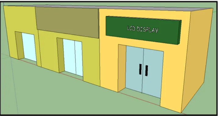
[image:23.612.189.546.132.323.2]When the system consist of hardware and software function properly, the model for the project is then can be design. Below is the design of the model.
9
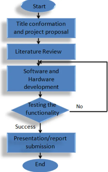
[image:24.612.228.451.122.476.2]1.4. Methodology
Figure 1.3: Basic Project Flowchart