STRUCTURAL ELEMENTS RETROFITTED WITH GFRP
UNDER CYCLIC LOADING
I G Shaaban
Zagazig University
A M Torkey
Cairo UniversityEgypt
ABSTRACT. The aim of this study is to evaluate the improvement in seismic behavior of
Reinforced Concrete (RC) structural elements as a result of retrofitting such elements using Glass Fiber Reinforced Plastics (GFRP) or enhancing the concrete quality using High Strength Concrete (HSC). A mathematical model was developed for the analysis of RC structures wrapped with FRP and linked to the inelastic damage analysis computer program IDARC3M, developed earlier by the authors for the analysis of HSC structural frames. The results predicted by the developed model were in good agreement with the experimental results obtained in the literature. The predicted results showed that wrapping the studied frame connection with GFRP improved its ductility and increased its capacity over the control connection (before retrofitting) by 82% and 160%, respectively. On the other hand, the analysis of HSC studied column using the computer program showed a large increase in its capacity. However, special precautions should be taken to achieve good confinement in order to obtain acceptable ductility of HSC structural elements.
Keywords: Glass Fiber Reinforced Plastics (GFRP), Retrofitting; High Strength Concrete
(HSC), Frame connections, confinement.
I G Shaaban is an associate professor for the analysis and design of RC structures in Civil
Engineering Department at Zagazig University (Banha Branch), Cairo, Egypt. He obtained his MSc from Ain Shams University, Cairo, Egypt, in 1988 and his PhD from University of Dundee, Scotland, U.K, in 1993. His research interests include the structural behavior of RC and high strength concrete structures (HSC), nonlinear static and dynamic analysis of such structures, repair and strengthening of RC structures, concrete durability and its relation to the design of reinforced concrete structures.
INTRODUCTION
Recent earthquakes in many parts of the world have illustrated the vulnerability of reinforced concrete structures to moderate and strong ground motions. This requires special attention for the analysis and design of building frames such as ductility in frame connections and strong column-weak beam systems [1]. Several investigations studied the use of High Strength Concrete (HSC) in building columns in seismic areas [2]. Experimental results have indicated that the ductility of HSC columns was improved by providing an appropriate confining reinforcement [3]. Existing structures that were designed according to earlier codes may not meet current seismic design standards since many of them are inadequate and pose a severe risk during seismic events. Vulnerable structures may be retrofitted to assure compliance with current design provisions. Among the several methods for retrofitting structural elements, advanced composites, or Fiber Reinforced Plastics (FRP), promise to provide substantially improved load capacity, durability and ductility of such elements [4].
Saadatmanesh et. al. [5] found that both flexural strength and displacement ductility for columns retrofitted by Glass Fiber Reinforced Plastics (GFRP) were higher than those of the original columns. Triantafillou et. al. [6] found that the strengthening of RC beams with FRP plates improved their flexural resistance and decreased the deflection. Chajes et. al. [7] found that beams wrapped with composite reinforcement (GFRP) displayed excellent bond characteristics and an increase in ultimate strength of 60 to 150% was achieved. In addition, it was shown that orientation of the fabrics' fibers influenced the shear strength contribution. Salah-Eldeen et. al. [8] found that Carbon Fiber Reinforced Plastics (CFRP) strips are efficient as a compression reinforcement to avoid concrete crushing failure and to enhance ultimate moment capacity for the repaired beams. Shaheen et. al. [9] found that the use of GFRP sheets for the strengthening of exterior R.C column-to-beam connections improved the ductility of these joints and increased their capacity by approximately 50%. Despite that the improvement of the behavior of structural elements by using GFRP for strengthening them or using HSC for constructing such elements was studied in the literature, as indicated, investigations for comparing the responses of both of them to seismic loading are limited.
The objective of this paper is to evaluate the improvement in the performance of structural elements under simulated seismic loads. Such improvement is achieved either by enhancing the concrete quality using HSC or by retrofitting such elements using advanced composites (GFRP). Ultimate strength results and ductility measures were used to monitor the improvement of structural elements.
MODELLING OF R.C SECTION WRAPPED WITH FRP STRIPS
The stress strain model adopted for concrete sections externally reinforced with fiber composite straps [10] is shown in Figure 1. The model is based on an equation proposed by Popovics [11] in which the longitudinal compressive concrete stress " fc " is defined as
follows:
f
c= -
f'
cc x r0)
Where
Sec
Ei
Ei E
sec
Esec
=f'cc/
ecc
s cc ~ £ co 1 + 5 f ' c
(2)
(3)
(4)
(5)
Where
f e e = f co [2.254
E i = 51000 ( f 'c o)1 / 3
f' co co
(6)
(7)
f 'c o = the unconfined concrete strength, MPa (N/mm ).
f 'c c = the compressive strength of confined concrete, (N/mm ).
s c = the longitudinal compressive strain of concrete,
s c c = strain at maximum concrete stress fcc of confined concrete,
• co= 0.002 strain at maximum concrete stress f c of unconfined concrete,
Ej = initial tangent modulus of elasticity of concrete, (N/mm2), divided by Poisson's ratio [4],
Esec = s e c a nt modulus of elasticity of concrete at peak stress, and f. = effective lateral confining pressure from transverse reinforcement.
Eco 2Eco ECC
[image:3.443.108.328.432.557.2]STRAIN,
The effective lateral confining pressure from transverse reinforcement on circular concrete sections as proposed by Mander et. al. [12] is defined as:
fie = fi kc (8)
and
ke = Ac/ Ac c (9)
Where
fi = lateral pressure from transverse reinforcement. kc = confinement effectiveness coefficient.
Ae = area of effectively confined concrete core.
Acc = effective area of concrete enclosed by composite strap.
Acc = Ac (1 - pc c) (10)
Where
pcc = ratio of area of longitudinal reinforcement to gross area of concrete.
Ac = area of concrete enclosed by composite strap.
Sheikh and Uzmeri [13] determined the effective area of confined concrete, Ae, considering
that an arching action occurs between straps in the form of a second-degree parabola as shown in Figure 2,
Ae = JI/4 [ ds- S 7 2 ]2 (11)
Where
S' = clear vertical spacing between straps, and ds = diameter of column.
Substituting Equations (10) and (11) into Equation (9), the confinement effectiveness coefficient of circular sections can be calculated as:
K. „ = _ S
"2 d s
For rectangular concrete sections, it is necessary to modify the effective lateral confining pressure, fie, by modifying the effective area of confined concrete assuming again the same approach of arching action (in the form of a second-degree parabola), as was shown in Figure 2 for circular columns.
Ae = h b ( l - S 7 2 h ) ( l - S72b) (13)
Where
Substituting Equations (10) and (13) into Equation (9) results in the confinement effectiveness coefficient for rectangular sections given by:
_ S _ S l - p
cc (14)
The material model for RC sections wrapped with FRP can be easily linked to any nonlinear finite element package. The computer program IDARC3M, developed earlier by the authors for the analysis of HSC structures [14], was modified for the analysis in this study. Linking the material model for RC sections wrapped with FRP was carried out as a further development of the program. The ultimate stresses of confined specimens (at strap fracture) were obtained experimentally [15] in a range of 2% to 4% of the ultimate tensile strength of the FRP sheet. The corresponding maximum strain was approximately 1.5%. Such experimental results are used as input data for the further development of the computer program. The program was verified by comparing its results with experimental results in the literature.
Strap
SECTION A-A
[image:5.443.73.368.253.385.2]SECTION B-B
Figure 2 Confinement of FRP straps for circular columns [10]
COMPARISON BETWEEN EXPERIMENTAL AND THEORETICAL RESULTS
Exterior Frame Connections Retrofitted with FRP under Cyclic Loading
r - I*
~s
• 8
•S
—1250 mm
[image:6.443.69.372.64.199.2]-1500 rr Sec. (2-2)
Figure 3 Details of strengthening using GFRP layers [15].
(a) Control specimen "Jl"
Specimen J l , the reference specimen, was used to investigate the behavior of the original specimen prior to strengthening using GFRP. The mode of failure of the specimen was a combination of brittle shear failure in the joint region and slippage of the stirrup hanger [15].
Load-displacement relationship
The load-displacement hysteresis loops are shown in Figure 4. It can be seen from the figure that there is a good agreement between the results predicted by the proposed model, linked to the computer program IDARC3M, and the experimental results obtained by Haddad [15]. However, the predicted results are slightly higher than the experimental ones, which indicates the conservative behavior of the proposed model. Figure 4 shows that the behavior of the specimen changed along the two parts of the cycle (negative and positive parts). Such difference in the behavior appeared clearly for the experimental results [15]. This can be attributed to the fact that the specimen reinforcement was not symmetric in the beam part as shown in Figure 3, Sec. 2-2.
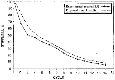
Stiffness degradation
The stiffness degradation or the cracked stiffness was calculated at each loading cycle as the ratio of the sum of peak tension and compression loads to the sum of the maximum tension and compression displacement. Both of the experimental and theoretical results for stiffness degradation versus number of cycles are shown in Figure 5. It can be seen from the figure that the experimental results are well predicted by the proposed model. Figure 5 shows that the specimen lost approximately 90% of its initial stiffness after 13 cycles only.
(b) Specimen retrofitted with GFRP "J6"
-20
-30
-40
-50
-60
Experimental results [15] ———1 Proposed model results 1
MUM
[image:7.443.123.327.59.235.2]-70 -60 -50 -40 -30 -20 -10 0 10 20 30 40 50 60 70 DISPLACEMENT, mm
Figure 4 Load-displacement hysteresis loops for Specimen Jl
Experimental results [15] • Proposed model results
8 9 10 11 12 13 14 15 CYCLE
Figure 5 Stiffness degradation for Specimen Jl
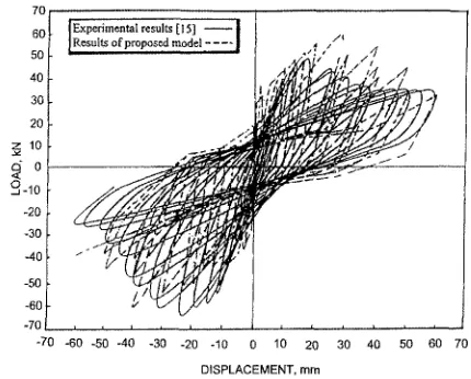
Load-displacement hysteresis loops
[image:7.443.122.323.287.427.2]It is worth mentioning that the peak value of the predicted negative load of Specimen J6 was almost equals to the experimental one and it took place at a higher value of displacement. It is interesting to notice that the behavior of the specimen along both of the negative and positive parts of the cycle is almost the same. It can be argued that although the steel reinforcement is not symmetric around X-axis as mentioned earlier for Specimen Jl (see Figure 4) but the wrapping with GFRP symmetrically around the beam's X-axis changed the behavior of the specimen.
70
60
40
30
20
1 10
Sic
-20
-30
-40
-50
-60 -70
Experimental results [ 15] — I Results of proposed model j
[image:8.443.105.320.163.336.2]-70 -60 -50 -40 -30 -20 -10 0 10 20 30 40 50 60 70 DISPLACEMENT, mm
Figure 6 Load-displacement hysteresis loops for Specimen J6.
Energy dissipation
The relationship between the energy dissipation and the cycle number for Specimens Jl and J6 is shown in Figure 7. The figure shows a very close agreement between the experimental and theoretical energy dissipation for Specimen J6 except for the cycles 6 to 11. At this range of cycles, the theoretical values were higher than the experimental ones by approximately 18 %. This may be attributed to the formation of cracks and peeling of GFRP layers through these cycles. Such peeling of GFRP is not included into the proposed model. The theoretical energy dissipation of Specimen J6 was higher than that of Jl up to the last cycle of loading for Specimen Jl (Cycle number 14) by approximately 135 %. In addition, Specimen J6 resisted higher number of loading cycles (17 cycles) till failure compared with Specimen J l , which is an indication of the improvement of capacity and ductility of this specimen.
Ultra High Strength Concrete (UHSC) Columns under Cyclic Loading
~ Results of proposed model J 6 Experimental results [15]
[image:9.443.124.334.59.184.2]2 3 4 5 6 7 8 9 10 11 12 13 14 15 16 17 18
Figure 7 Energy dissipation for Specimen Jl and J6
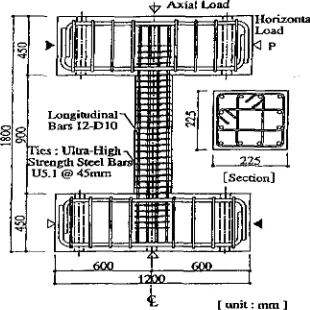
Ultra high strength deformed bars with yield strength of 1380 MPa were used for both longitudinal and lateral reinforcement. Among the experimentally tested specimens, Specimen "UC15L" was modeled analytically using program IDARC3M [14]. The specimen had twelve longitudinal bars of diameter 10mm and four branches lateral ties of diameter 6.4mm every 35mm and 45mm, respectively. It was subjected to axial stress ratio of 0.36, which is considered low compared with the other test specimens [16]. Reversed cyclic horizontal load under double curvature was applied to each specimen while axial compression was held constant. Loading program consisted of each one cycle at displacement angle of 0.2, 0.33, 0.5 and 0.75% followed by each two cycles at displacement angle of 1.0, 1.5, 2.0, 3.0, 4.0 and 5.0%.
Ties: Ultra-High-* Strength SKcl Bars I f f U5.1 @ 45mm
[image:9.443.143.298.345.500.2]225 [Section]
( unit: mm ]
Figure 8 Testing of ultra High Strength Concrete (HSC) columns [16]
Load-displacement hysteresis loops
It can be seen from the figure that, generally, the predicted results are in good agreement with those obtained experimentally. For example, the maximum load obtained experimentally was 355 kN approximately and the predicted load was higher than this value by 11% only.
500 4O0 300 200 * 100
Results of proposed model -Experimental Results [16] —
Crushing of concrete
Longitudinal ba*~_2JW
Yielding in t e n s i o n ^ " ^
/ - Longitudinal bar yielding in tension
-Longitudinal bar yielding in compression •
Axial Load = 2089 KN
[image:10.443.120.328.98.242.2]DRIFT (X 0.001 rad)
Figure 9 Load displacement loops for Specimen UC15L
COMPARISON BETWEEN THE BEHAVIOR OF NSC STRUCTURAL ELEMENTS
RETROFITTED WITH FRP AND HSC STRUCTURAL ELEMENTS
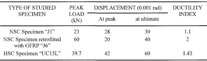
It was difficult to compare the responses of studied structural elements to cyclic loading since these elements are different in shape, dimensions and in the loading scheme. However, the behavior of such elements can be assessed from the predicted load and displacement results obtained from Figures 4, 6 and 9 and tabulated in Table 1. It can be noticed from the table that using GFRP in retrofitting the studied connection raised the peak load from 23 kN to 60 kN (almost 160% increase in the capacity). Table 1 shows that the capacity of the studied HSC element is very high compared to the other specimens. .An attempt to compare the ductility of studied elements was carried out by dividing the ultimate displacement of each of them by the displacement at the peak load (Ductility index). The table shows that the ductility index of the specimen retrofitted with GFRP is the best among the studied elements (higher than that of Specimen Jl by 82%). It is interesting to note that the ductility index of the HSC element is higher than the NSC element before retrofitting with GFRP by 30%. This may be attributed to the fact that the studied HSC structural element is well confined by a large number of high tensile strength stirrups.
Table 1 Predicted Results for Different Structural Elements
TYPE OF STUDIED SPECIMEN
NSC Specimen " J l " NSC Specimen retrofitted
with GFRP "J6" HSC Specimen "UC15L"
PEAK LOAD -(kN) 23 60 39.7
DISPLACEMENT (0.001 rad)
[image:10.443.50.399.493.596.2]CONCLUSIONS
The mathematical model developed for the analysis of RC sections wrapped with FRP was successfully linked to the computer program IDARC3M and used in studying the behavior of frame connections under cyclic loading. The results predicted by the developed model were in good agreement with the experimental results obtained in the literature.
The studied connection retrofitted by GFRP showed an improvement in both capacity and ductility over the control connection (before retrofitting) by 160% and 82%, respectively.
The energy dissipation of the connection retrofitted with GFRP was higher than that of the control one by approximately 135 %. Moreover, this studied connection resisted higher number of loading cycles (17 cycles) till failure compared with the control specimen, which is an indication of the improvement of capacity and ductility of this specimen.
Despite the fact that using HSC in structural elements leads to a great increase in the capacity, special precautions should be taken to achieve good confinement in order to obtain acceptable ductility of such elements. On the other hand, using FRP for strengthening structural elements improves the ultimate capacity to acceptable degree and enhances the ductility, which is preferable for seismic design.
REFERENCES
1. MAZZONI S., MOEHLE J. P., "Seismic Response of Beam-Column Joints in Double-Deck Reinforced Concrete Bridge Frames," ACI Structural Journal, Vol. 98, No. 3, May-June 2001, pp. 259-269.
2. AZIZINAMANI A., KUSKA S., BRUNGARDT P., HATFIELD E., "Seismic Behavior of Square High Strength Concrete Columns", ACI Structural Journal, Vol. 91, No. 3, 1994, pp 336-345.
3. NISHIYAMA M., FUKUSHIMA I., WATANABE F., MUGURUMA H., "Axial Loading Tests on Strength Concrete Prisms Confined By Ordinary and High-Strength Steel," Proceedings, High-High-Strength Concrete 1993, Lillehammer Norway, pp. 322-329.
4. TOUTANJI H.A., "Stress-Strain Characteristics of Concrete Columns Externally Confined with Advanced Fiber Composite Sheets", ACI Structural Journal, Vol. 96, No.3, May-June 1999, pp.397-404.
5. SAADATMANESH H, EHSANI M.R, JIN L, "Repair of Earthquake-Damaged RC Columns with FRP Wraps," ACI Structural Journal, Vol. 94, No. 2, March-April, 1997, pp. 206-215.
6. TRIANTAFILLOU T.C, DESKOVIC N, DEURING M, "Strengthening of Concrete Structures with Prestressed Fiber Reinforced Plastic Sheets," ACI Structural Journal, Vol. 89, No. 3, May-June 1992, pp. 235-244.
8. SALAH-ELDEEN O, KORANY Y., ABDEL-LATIF H., "Application of CFRP Strips in Repairing Reinforced Concrete Beams," Proceedings of the Arab Conference for Repair and Rehabilitation of Structures, Vol. 1, 1998, pp.519-538.
9. SHAHEEN H. H., KHALEEL G. I., HUSSEIN Y. M, "Repair of Exterior Space Beam-Column Joints," The International Workshop on Structural Composites for Infrastructure Applications, Cairo, Egypt, May 2001, pp. 139-152.
10. SAADATMANESH FL, EHSANI M.R., LI M.W, "Strength and Ductility of Concrete Columns Externally Reinforced with Fiber Composite Straps", ACI Structural Journal, V91, No.4, July-August 1994, pp.434-447.
11. POPOVICS, S., "Numerical Approach to the Complete Stress-Strain Curves for Concrete, "Cement and Concrete Research, Vol. 3, No. 5, 1973, pp. 583-599.
12. MANDER J. B., PRIESTLEY M. J. N., PARK R., "Theoretical Stress-Strain Model for Confined Concrete," Journal of Structural Engineering, ASCE, Vol. 114, No. 8, Aug. 1988, pp. 1804-1826.
13. SHEIKH S. A., UZUMERI S. M., "Strength and Ductility of Tied Concrete Columns, "Journal of Structural Division, ASCE, Vol. 106, No. 5, 1980, pp. 1079-1102.
14. SHAABAN I. G., TORKEY A. M., "Nonlinear Seismic Analysis of High Strength ConcreteStructures," Journal of the Egyptian Society of Engineers, Vol. 39, No. 2, 2000.
15. HADAD H.S., "Strengthening of the Exterior Beam-Column Connections with GFRP (to resist cyclic loading)", Ph.D Thesis submitted to faculty of engineering, Cairo University, 2000,217 pp.
![Figure 1 Modeling of stress-strain relationship for unconfined and confined concrete [10].](https://thumb-us.123doks.com/thumbv2/123dok_us/8061609.226091/3.443.108.328.432.557/figure-modeling-stress-strain-relationship-unconfined-confined-concrete.webp)
![Figure 2 Confinement of FRP straps for circular columns [10]](https://thumb-us.123doks.com/thumbv2/123dok_us/8061609.226091/5.443.73.368.253.385/figure-confinement-frp-straps-circular-columns.webp)
![Figure 3 Details of strengthening using GFRP layers [15].](https://thumb-us.123doks.com/thumbv2/123dok_us/8061609.226091/6.443.69.372.64.199/figure-details-strengthening-using-gfrp-layers.webp)