AU3378_TitlePage 11/16/05 8:59 AM Page 1
Boca Raton New York
Wireless
Security
Handbook
Taylor & Francis Group
6000 Broken Sound Parkway NW, Suite 300 Boca Raton, FL 33487-2742
© 2006 by Taylor & Francis Group, LLC Auerbach is an imprint of Taylor & Francis Group No claim to original U.S. Government works
Printed in the United States of America on acid-free paper 10 9 8 7 6 5 4 3 2 1
International Standard Book Number-10: 0-8493-3378-4 (Hardcover) International Standard Book Number-13: 978-0-8493-3378-1 (Hardcover) Library of Congress Card Number 2005049924
This book contains information obtained from authentic and highly regarded sources. Reprinted material is quoted with permission, and sources are indicated. A wide variety of references are listed. Reasonable efforts have been made to publish reliable data and information, but the author and the publisher cannot assume responsibility for the validity of all materials or for the consequences of their use.
No part of this book may be reprinted, reproduced, transmitted, or utilized in any form by any electronic, mechanical, or other means, now known or hereafter invented, including photocopying, microfilming, and recording, or in any information storage or retrieval system, without written permission from the publishers. For permission to photocopy or use material electronically from this work, please access www.copyright.com (http://www.copyright.com/) or contact the Copyright Clearance Center, Inc. (CCC) 222 Rosewood Drive, Danvers, MA 01923, 978-750-8400. CCC is a not-for-profit organization that provides licenses and registration for a variety of users. For organizations that have been granted a photocopy license by the CCC, a separate system of payment has been arranged.
Trademark Notice: Product or corporate names may be trademarks or registered trademarks, and are used only
for identification and explanation without intent to infringe.
Library of Congress Cataloging-in-Publication Data
Earle, Aaron E.
Wireless security handbook / Aaron E. Earle. p. cm.
Includes bibliographical references and index. ISBN 0-8493-3378-4 (alk. paper)
1. Wireless LANs--Security measures. 2. Wireless communication systems--Security measures. I. Title.
TK5105.78.E23 2005
005.8--dc22 2005049924
Visit the Taylor & Francis Web site at
http://www.taylorandfrancis.com
and the Auerbach Publications Web site at
http://www.auerbach-publications.com
AUERBACH PUBLICATIONS
www.auerbach-publications.comTo Order Call: 1-800-272-7737 • Fax: 1-800-374-3401 E-mail: [email protected]
Asset Protection and Security Management Handbook
POA Publishing ISBN: 0-8493-1603-0
Building a Global Information Assurance Program
Raymond J. Curts and Douglas E. Campbell ISBN: 0-8493-1368-6
Building an Information Security Awareness Program
Mark B. Desman ISBN: 0-8493-0116-5
Critical Incident Management
Alan B. Sterneckert ISBN: 0-8493-0010-X
Cyber Crime Investigator’s Field Guide
Bruce Middleton ISBN: 0-8493-1192-6
Cyber Forensics: A Field Manual for Collecting, Examining, and Preserving Evidence of Computer Crimes
Albert J. Marcella, Jr. and Robert S. Greenfield ISBN: 0-8493-0955-7
The Ethical Hack: A Framework for Business Value Penetration Testing
James S. Tiller ISBN: 0-8493-1609-X
The Hacker’s Handbook: The Strategy Behind Breaking into and Defending Networks
Susan Young and Dave Aitel ISBN: 0-8493-0888-7
Information Security Architecture: An Integrated Approach to Security in the Organization
Jan Killmeyer Tudor ISBN: 0-8493-9988-2
Information Security Fundamentals
Thomas R. Peltier ISBN: 0-8493-1957-9
Information Security Management Handbook, 5th Edition
Harold F. Tipton and Micki Krause ISBN: 0-8493-1997-8
Information Security Policies, Procedures, and Standards: Guidelines for Effective Information Security Management
Thomas R. Peltier ISBN: 0-8493-1137-3
Information Security Risk Analysis, 2nd Edition
Thomas R. Peltier ISBN: 0-8493-3346-6
Information Technology Control and Audit
Fredrick Gallegos, Daniel Manson, and Sandra Allen-Senft
ISBN: 0-8493-9994-7
Investigator’s Guide to Steganography
Gregory Kipper ISBN: 0-8493-2433-5
Managing a Network Vulnerability Assessment
Thomas Peltier, Justin Peltier, and John A. Blackley ISBN: 0-8493-1270-1
Network Perimeter Security: Building Defense In-Depth
Cliff Riggs
ISBN: 0-8493-1628-6
The Practical Guide to HIPAA Privacy and Security Compliance
Kevin Beaver and Rebecca Herold ISBN: 0-8493-1953-6
A Practical Guide to Security Engineering and Information Assurance
Debra S. Herrmann ISBN: 0-8493-1163-2
The Privacy Papers: Managing Technology, Consumer, Employee and Legislative Actions
Rebecca Herold ISBN: 0-8493-1248-5
Public Key Infrastructure: Building Trusted Applications and Web Services
John R. Vacca ISBN: 0-8493-0822-4
Securing and Controlling Cisco Routers
Peter T. Davis ISBN: 0-8493-1290-6
Strategic Information Security
John Wylder ISBN: 0-8493-2041-0
Surviving Security: How to Integrate People, Process, and Technology, Second Edition
Amanda Andress ISBN: 0-8493-2042-9
A Technical Guide to IPSec Virtual Private Networks
James S. Tiller ISBN: 0-8493-0876-3
Using the Common Criteria for IT Security Evaluation
Debra S. Herrmann ISBN: 0-8493-1404-6
v
Contents
1
Wireless Network Overview1.1 RF Overview
1.2 Wireless Signal Propagation 1.2.1 Reflection
1.2.2 Refraction 1.2.3 Diffraction 1.2.4 Scattering 1.2.5 Absorption 1.3 Signal-to-Noise Ratio 1.4 Modulation
1.4.1 Amplitude Modulation 1.4.2 Frequency Modulation 1.4.3 Phase Modulation
1.4.4 Complementary Code Keying (CCK) 1.4.5 Quadrature Amplitude Modulation (QAM) 1.5 Wireless Groups
1.5.1 International Telecommunications Union (ITU) 1.5.2 International Telecommunications Union Radio
Sector (ITU-R)
1.5.3 Federal Communications Commission (FCC)
1.5.4 Conference of European Post and Telecommunications (CEPT)
1.5.5 Wi-Fi Alliance 1.5.6 IEEE
1.6 Chapter 1 Review Questions
2
Risks and Threats of Wireless2.1 Goals of Information Security 2.1.1 Confidentiality 2.1.2 Availability 2.1.3 Integrity 2.2 Analysis
vi Wireless Security Handbook
2.4 Denial-of-Service 2.5 Malicious Code.. 2.6 Social Engineering 2.7 Rogue Access Points 2.8 Cell Phone Security
2.9 Wireless Hacking and Hackers 2.9.1 Motives of Wireless Hackers 2.9.2 War Drivers
2.9.3 War Walkers 2.9.4 War Chalking 2.9.5 War Flying 2.9.6 Bluejacking 2.9.7 X10 Driving
2.9.8 Cordless Phone Driving 2.9.9 War Dialing
2.9.10 Tracking War Drivers
2.10 RFID
2.11 Chapter 2 Review Questions
3
The Legality of Computer Crime3.1 Electronic Communications Privacy Act 3.2 Computer Fraud and Abuse Act
3.2.1 Patriot Act
3.3 State Computer Crime Issues 3.4 Chapter 3 Review Questions
4
Wireless Physical Layer Technologies4.1 ISM Spectrum
4.2 Frequency Hopping Spread Spectrum (FHSS) 4.3 Direct Sequence Spread Spectrum (DSSS)
4.4 Orthogonal Frequency Division Multiplexing (OFDM) 4.5 Chapter 4 Review Questions
5
Wireless Management Frames5.1 Beacon
5.2 Probe Request 5.3 Probe Response 5.4 Authentication 5.5 Association Request 5.6 Association Response
5.7 Disassociation and De-Authentication
5.8 CSMA/CA
5.8.1 RTS
5.8.2 CTS
5.8.3 DATA
5.8.4 ACK
5.9 Fragmentation
5.10 Distributed Coordination Function 5.11 Point Coordination Function 5.12 Interframe Spacing
5.13 Service Set Identifier (SSID) 5.14 Chapter 5 Review Questions
6
Wireless Local and Personal Area Networks6.1 Ad Hoc Mode
6.2 Infrastructure Mode 6.3 Bridging
6.4 Repeater
6.5 Mesh Wireless Networks
6.6 Local Area Networking Standards 6.6.1 802.11
6.6.2 802.11a. 6.6.3 802.11b 6.6.4 802.11c 6.6.5 802.11d 6.6.6 802.11e 6.6.7 802.11f 6.6.8 802.11g 6.6.9 802.11h 6.6.10 802.11i 6.6.11 802.11j 6.6.12 802.11n
6.6.13 Real-World Wireless Data Rates 6.7 Personal Area Network (PAN) 802.15
6.7.1 Bluetooth 802.15.1 6.7.2 Infrared (IR)
6.7.3 Ultrawide Band 802.15.3 6.7.4 ZIGBEE 802.15.4 6.8 Chapter 6 Review Questions
7
Wide Area Wireless Technologies7.1 Cell Phone Technologies 7.1.1 Analog
7.1.2 TDMA
7.1.3 CDMA
7.1.3.1 CDMA2000
7.1.3.2 CDMA 1xEV-DO and CDMA 1xEV-DV
7.1.4 GSM.
7.1.4.1 GPRS.
7.1.4.2 GSM Security System Overview
7.2 GPS
viii Wireless Security Handbook
7.4 802.20 Standard
7.5 Chapter 7 Review Questions .
8
Wireless Antenna Theory8.1 RF Antenna Overview 8.1.1 Polarization 8.1.2 Gain
8.1.2.1 Equivalent Isotropic Radiated Power (EIRP). 8.1.3 Beamwidth
8.1.4 Path Loss 8.1.5 Azimuth 8.1.6 Multipath 8.1.7 Antenna Diversity 8.2 Fresnel Zone
8.3 Antenna Types
8.3.1 Directional Antennas. 8.3.2 Omni-Directional Antennas 8.3.3 Homemade Antennas 8.4 Connectors
8.4.1 N Connectors.
8.4.2 Reverse-Polarity TNC-Type Connector (RP-TNC) 8.4.3 SMA, RP-SMA, and RSMA
8.4.4 MC and MMX
8.5 Chapter 8 Review Questions
9
The Wireless Deployment Process9.1 Gather Requirements 9.2 Estimation.
9.3 Make the Business Case 9.4 Site Survey
9.4.1 Performing the Site Survey 9.4.2 Technical Controls 9.4.3 Financial Controls .
9.5 Design
9.6 Staging
9.7 Deployment and Installation. 9.8 Certification
9.9 Audit
9.10 Chapter 9 Review Questions
10
Wireless Access Points10.1 Linksys Access Points 10.2 Cisco Access Points
10.2.1 Cisco Aironet 350 Series. 10.2.2 Cisco 1200 Series Access Point 10.2.3 Cisco 1100 Series Access Point
11
Wireless End Devices11.1 Laptops 11.2 Tablets 11.3 PDA Devices
11.3.1 Palm
11.3.2 Microsoft CE and Pocket PC 11.3.3 BlackBerry RIM OS
11.3.4 Symbian OS 11.3.5 Linux 11.4 Handheld Scanners 11.5 Smart Phones 11.6 Wi-Fi Phones
11.7 Chapter 11 Review Questions
12
Wireless LAN Security12.1 Wireless LAN Security History 12.2 Authentication
12.2.1 Shared Key Authentication 12.2.2 Open Key Authentication 12.3 SSID
12.4 Wireless Security Basics
12.5 Equivalent Privacy Standard (WEP) 12.5.1 WEP Encryption Process 12.6 802.1x
12.6.1 Authentication Server 12.6.2 Authenticator 12.6.3 Supplicant
12.6.4 Extensive Authentication Protocol over Local Area Network (EAPOL)
12.7 Remote Authentication Dial-In User Service (RADIUS) 12.8 Extensible Authentication Protocol (EAP)
12.8.1 EAP-MD5 12.8.2 EAP-TLS 12.8.3 EAP-TTLS 12.8.4 LEAP 12.8.5 PEAP 12.8.6 EAP-FAST
12.9 Wi-Fi Protected Access (WPA) 12.10 802.11i
12.10.1 Robust Secure Network (RSN)
12.10.1.1 Transition Secure Network (TSN) 12.10.2 Temporal Key Integrity Protocol (TKIP)
12.10.2.1 TKIP Message Integrity Check (MIC) 12.10.3 Advanced Encryption Standard (AES)
12.10.4 802.11i System Overview 12.11 Wi-Fi Protected Access (WPA2)
x Wireless Security Handbook
12.13 Rogue Access Points Detection 12.14 Chapter 12 Review Questions
13
Breaking Wireless Security13.1 The Hacking Process
13.1.1 Information Gathering 13.1.2 Enumeratio
13.1.3 Compromise
13.1.4 Expanding Privileges and Accessibility 13.1.5 Cleaning up the Trails
13.2 Wireless Network Compromising Techniques 13.2.1 WEP
13.2.1.1 Stream Cipher Attack 13.2.1.2 Known Plaintext Attack 13.2.1.3 Dictionary Building Attack 13.2.1.4 Double Encryption Attack 13.2.1.5 Message Modification Attack 13.2.2 Denial-of-Service (DoS) Attacks
13.2.2.1 EAP DoS Attacks 13.2.3 MAC Filtering Attack 13.2.4 Cisco LEAP Vulnerabilities 13.2.5 RADIUS Vulnerabilities 13.2.6 802.1x Vulnerabilities 13.2.7 Attack on Michael
13.2.8 Attacks on Wireless Gateways 13.2.9 Attacks on WPA and 802.11i 13.3 Access Point Compromising Techniques
13.3.1 Remote Management Attacks 13.3.1.1 Telnet
13.3.1.2 HTTP 13.3.1.3 RADIUS 13.3.1.4 SNMP 13.4 Chapter 13 Review Questions
14
Wireless Security Policy14.1 Policy Overview 14.1.1 Policies 14.1.2 Standards 14.1.3 Guidelines 14.1.4 Procedures 14.2 The Policy-Writing Process 14.3 Risk Assessment
14.3.1 Exposure Factor (EF)
14.3.2 Annualized Rate of Occurrence (ARO) 14.3.4 Single Loss Expectancy (SLE)
14.3.5 Annualized Loss Expectancy (ALE)
14.5 Wireless Security Policy Areas 14.5.1 Password Policy 14.5.2 Access Policy 14.5.3 Public Access 14.5.4 Physical Security 14.6 Chapter 14 Review Questions
15
Wireless Security Architectures15.1 Static WEP Wireless Architecture
15.2 VPN
15.2.1 Technology Overview. 15.2.1.1 IPSec 15.2.1.2 ISAKMP
15.2.1.3 Internet Key Exchange (IKE) 15.2.1.4 AH
15.2.1.5 ESP
15.3 Wireless VPN Architecture Overview 15.4 VPN Policy Aspect
15.5 Wireless Gateway Systems 15.6 802.1x
15.7 Comparing Wireless Security Architectures 15.7.1 WEP Architecture
15.7.2 Wireless VPN Architecture
15.7.3 Wireless Gateway or Firewall Architecture 15.7.4 Wireless 802.1x Architecture
15.8 Chapter 15 Review Questions
16
Wireless Tools16.1 Scanning Tools.
16.1.1 Network Stumbler 16.1.2 MiniStumbler 16.1.3 Wellenreiter 16.1.4 Wavemon 16.2 Sniffing Tools
16.2.1 AiroPeek 16.2.2 Sniffer Pro 16.2.3 Mognet 16.3 Hybrid Tools
16.3.1 Kismet 16.3.2 AirTraf 16.3.3 AirMagnet 16.4 Denial-of-Service Tools
16.4.1 WLAN-Jack 16.4.2 FATA-Jack. 16.5 Cracking Tools .
xii Wireless Security Handbook
16.5.3 BSD-Airtools 16.5.4 ASLEAP
16.6 Access Point Attacking Tools 16.6.1 Brutus
16.6.2 SolarWinds
16.6.2.1 Port Scanner Tool.
16.6.2.2 SNMP Brute Force Attack Tool. 16.6.2.3 SNMP Dictionary Attack Tool. 16.6.2.4 Router Password Decryption Tool 16.6.3 Cain and Able
16.7 Other Wireless Security Tools 16.7.1 EtherChange 16.7.2 Achilles
16.8 Chapter 16 Review Questions
xiii
Preface
This book was written to give the reader a well-rounded understanding of wireless network security. It looks at wireless from multiple perspec-tives, ranging from auditor, to security architect, to hacker. This wide scope benefits anyone who has to administer, secure, hack, or participate on a wireless network. Going through this book, the reader will see that it tackles the risk of wireless from many angles. It goes from a policy level to mitigate certain risks that wireless brings. It talks about the most cost-effective solutions to deploy wireless across a large enterprise. It talks about financial and technical controls that one can apply to reduce any unforeseen risk involved in a large wireless project. It covers the technical details of how to design, build, and hack almost all wir eless security methods.
Acknowledgments
I would like to thank many people who over the years have helped me get to where I am today. Great wisdom comes from one who knows that it is not what you do to advance, but rather what the people below you do to push you in that direction. I would like to thank my family and friends who have supported me throughout this endeavor, and my girl-friend Clare who did not complain about the long hours away from her spent writing this book. I would like to thank my father Douglas R. Earle, who purchased my first computer for me; my friend Justin Peltier, who gave me the “I can do it, you can do it” mentality; and my friend Paul Immo, who saw my passion for technology and helped me achieve my goals around education and certification. I would also like to thank my friend Jeremy Davison for allowing me to forget altogether about com-puters, networking, security, and technology and just have fun every now and then.
1
Chapter 1
Wireless Network
Overview
This chapter looks at radio frequencies (RF) in general. The goal of this chapter is to gain a general understanding of RF. This allows us to see what issues are inherent in all wireless communications, whether it is a cell phone or an 802.11g laptop. This knowledge can help us troubleshoot RF networks and understand what can and cannot be fixed. After reading this, we look at the many types of interference that affects all wireless communications. Once an understanding of interference is achieved, we look at modulation. We discuss the different types of modulation used on wireless networks and how each of them works. The final section of this chapter addresses the many wireless groups that create and regulate the way we use wireless communications.
1.1 RF Overview
2 Wireless Security Handbook
in the late 1880s; he expounded on James Clerk Maxwell’s research on the electromagnetic theory of light. Hertz found that by using a strong electrical signal it was possible to send that signal through nonconductive material; later, the notion of such material went out the door when Hertz discovered that the signal could conduct through the air. This is how radio signals and thus wireless communications were born.
As the radio waves travel across the air, a receiving antenna can take the wave and convert it back to an electrical signal. This signal would be the same as the one originally created by the sending electrical device. The way wireless propagates itself is very similar to dropping a stone into a large body of water. Once the stone hits the water, ripples are created, moving in all directions until the ripples are so minuscule that they no longer can be seen or detected.
Electromagnetic waves are produced by the motion of electrically charged particles. These waves are also called electromagnetic radiation
because they radiate from the electrically charged particles. All wireless devices have some form of electromagnetic waves. All these waves are part of the electromagnetic spectrum; this spectrum has all types of electromagnetic radiation classified. Although the size of this spectrum is infinite, the size of the radio portion is limited to around 100 kHz to 300 GHz. The waves discussed herein are mostly based in the microwave section of the radio spectrum. The larger an electromagnetic wave, the further it will travel. The fact is that when you look at radio waves, the amount of information being sent is small, and therefore the frequency used is also small. A small frequency signal has a very large wave. A radio wave, like the ones one picks up on a car radio, can be thought of as about the size of an adult elephant.
Now look at an x-ray wave. This is very high on the radio spectrum, so it will have a large amount of data traveling down a small wavelength. This wave might be as small or smaller than a single atom. This smaller x-ray wave will not travel as far as the radio wave because of its limited size.
In discussing frequency, one must understand how to measure it. When looking at a wave traveling in time, one can see the amount of times a signal wave is completed from an upper crest to its lower crest. Each time this is completed, it is a single cycle. When one measures the total amount of wave cycles in a particular amount of time, one gets a frequency. In general, one takes the amount of cycles in a single second, giving the hertz (Hz). In the case of wireless networks, this amount is so large that it is measured in gigahertz (GHz), which is one billion hertz.
When talking about power and wireless, there are a number of values commonly used to measure wireless power. The first value to look at is the Watt, the rate at which a device converts electrical energy into another
form of energy, such as light, heat, or — in this case — a wireless signal. The Watt can be measured in a number of ways, depending on how high or low a value it is compared to a single watt. What this means is if one has a value much greater than a single watt, maybe somewhere around 1000 watts, one would have a kilowatt (kW). This is because a kilowatt represents 1000 watts. Now, if one has less than a single watt, then one has a milliwatt (mW), which is 1/1000 of a watt. The milliwatt is the primary watt designation in relation to wireless local area networking.
The next term is the decibel. A decibel (or dB) is a mathematical — or, to be specific, a logarithmic ratio — that indicates the relative strength of a device’s electric or acoustic signal to that of another. This can be used by itself, although it is mostly used with a unit of measurement. Looking at wireless, the most common units of measurement used with the decibel are the milliwatt (dBm), the forward gain of an antenna compared to an imaginary isotropic antenna (dBi), and the forward gain of an antenna compared to a half-wave dipole antenna (dBd). Wireless networks are measured in decibel strength compared to one milliwatt. In wireless local area networking (WLAN), dBi and dBd are commonly used and a formula is often needed to convert these two expressions into each other so they an be correctly compared. Chapter 8 goes into greater detail about both isotropic and dipole antennas and power measurement. Until then, just remember that these two figures are the most commonly used measurements of wireless power.
When discussing bandwidth, most computer people associate it with network performance. In the wireless world, bandwidth has a slightly different meaning. The meaning we are looking for in relation to wireless has to do with the size or the upper and lower limit to the frequency we are using. When we compare frequency and bandwidth, we see that frequency is a specific location on the electromagnetic spectrum compared to wireless bandwidth, which is the range between two frequencies. A single channel on the 2.4-GHz frequency has a channel bandwidth of 20 MHz. This is an example of wireless bandwidth. Looking at network performance bandwidth, one would identify it as the following: the network WAN connection only has a bandwidth of 1.5 megabytes (MB).
1.2 Wireless Signal Propagation
4 Wireless Security Handbook
challenge throughout history that many governments from around the world have had to step in to make certain frequencies restricted from use. Restricting this use prevents interference caused by other wireless devices and makes for cleaner airwaves.
What happens to radio waves when interference affects their direction, influencing their signal clarity? Depending on what caused the interference, different common effects can occur. When the interference consists of certain objects, there are a number of well-documented, specifically proven results. When radio waves hit an object, they will bounce just like a child’s ball. They also have the ability to pass through some objects just as a ghost would. Being able to understand when each of these occurrences takes place is critical to understanding the operation of wireless.
1.2.1 Reflection
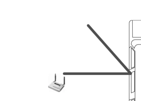
Reflection takes place when an electromagnetic wave impacts a large, smooth surface and bounces off. This can happen with large surfaces such as the ground, walls, buildings, and flooring. After reflection takes place, radio waves often radiate in a different direction than originally intended. As one can see in Figure 1.1, the signal has a main pathway that intersects with the object. As it hits the object, it bounces off and heads in a different direction. This reflecting action lowers the signal
Figure 1.1 Reflection.
[image:17.612.84.381.74.288.2]strength as it bounces off objects. Predominantly, the signal will pass through an object rather than bounce off of it. Reflection is one of the least obstructing interference types. This is because, for the most part, the signal remains whole; however, it moves in a different direction after it is reflected. Moreover, some of the other types of interference types will severely impact the signal’s quality.
1.2.2 Refraction
When a signal reflects off an object and passes through it at the same time, one obtains what is called refraction (see Figure 1.2). RF is very stubborn; it goes places one does not want it to. Walls, buildings, or floors that should reflect the signal often do not; RF waves have a tendency to penetrate these objects instead. Once the signal has penetrated through these obstacles, it now has a degraded signal strength, which prevents it from reaching as far as it could have before the refraction. This is why reflection is not as bad an inherent interference as refraction. When a signal is reflected, most of the signal quality and strength is reflected with it. Refraction takes place when the signal has a portion of it penetrating and a portion of it reflecting. When this happens, the quality and strength are greatly deteriorated.
1.2.3 Diffraction
Diffraction, which is similar to refraction, describes what a signal does when it encounters an object. In diffraction, after the signal makes it
6 Wireless Security Handbook
around the object, we often get a shadow area. This is because the signal will bend around objects as best it can; but without being able to penetrate through the object, there is a dead spot created directly behind the object. Diffraction, unlike refraction, describes how the signal beams around objects instead of passing through them. People tend to get the two confused. In diffraction, shadow areas are created when an object will not allow refraction to occur. To picture this, see Figure 1.3, which shows the signal bending around the object; in doing so, it creates a shadow area directly behind the object. If refraction took place instead of diffrac-tion, then the shadow area would not exist. This is because with refracdiffrac-tion, the signal would bleed through the object and be present directly behind it. Some of the confusion around diffraction and refraction has to do with receiving a signal directly behind an object that the signal cannot penetrate. There are cases where this is true. It is possible for a signal to be unable to refract through an object but still be able to reflect enough times between different objects to make it around the main object.
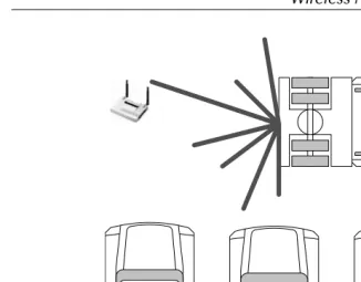
1.2.4 Scattering
Scattering (Figure 1.4) occurs when the RF signals encounter a rough surface or an area with tightly placed objects. The best way to understand scattering is to think of an automobile assembly line. In this scenario, one would see large amounts of robotic arms, raised metal-screened catwalks, pallets of metal doors, and many other objects. All these objects make the signal split into smaller signals, reducing the original signal’s strength. The main signal enters this area and reflects off the small metal objects and ping-pongs, thus creating more and more signals. Over time, this makes the main signal so scattered that its original strength diminishes. This is because when scattering takes place, the signal is equally divided among the many waves bouncing around the tightly packed area. On top
Figure 1.3 Diffraction.
Shadow Area
problems in receiving a signal. This is due to the fact that when multiple signals arrive at the receiver at the same time, it is difficult to correctly understand either of them.
1.2.5 Absorption
Just by the name, one can probably figure this one out. When a signal hits certain objects — mostly water-based objects such as trees, cardboard, or paper objects — the RF signal actually is absorbed into the object. This one interference problem plagues point-to-point or point-to-multipoint bridge operations. Trees having a large amount of water in them tend to absorb large amounts of signals trying to pass through them. Evergreen trees are the worst because they store the most water inside them. When trouble-shooting RF, beware of any large amounts of water-based products, objects, or stock. It often occurs that someone moves large amounts of palletized cardboard boxes and RF signals in that area diminish because of absorption.
1.3 Signal-to-Noise Ratio
Within wireless networks, many types of interference exist. Some may be avoidable and other types are always present. The type of interference
[image:20.612.58.384.58.313.2]8 Wireless Security Handbook
that is always present stems from the movement of electrons and the basic radiation of energy. This means that no matter what one does, there will always be a slight amount of interference present in any airspace. This small level of interference makes up what is called the “noise floor.” To send a wireless signal, one must be able to transmit a signal above the noise floor. Once this is accomplished, one must overcome another interference type called “impulse noise.” Impulse noise consists of irregular spikes or pulses at high amplitude in short durations. This kind of interference can be caused by a number of things, ranging from solar flares and lighting to microwaves and walkie-talkies.
The signal-to-noise ratio (SNR) helps wireless designers identify the quality of their transmissions. This is done by taking the signal power and dividing it by the noise power, producing the SNR value. This value is often measured in decibels (dB). The SNR value can help an RF designer understand how far the wireless area of coverage extends. In thinking about this, we are commonly under the mindset of increasing the power above the noise to fix our problems. Although this may be true, the FCC or, outside the United States, other government bodies regulate the amount of power a radio device can emit. However, this can impede one’s ability to easily get around interference issues by increasing power. The main goal of the government’s regulation is to prevent the basic radiation of energy from propagating out of proportion. If this was to happen, it would just increase the general noise floor for everyone, making it even more difficult to avoid interference.
Looking at SNR values, one needs to understand a couple of facts about different values. First, an SNR value of 3 dB is equal to 2:1, which means that the noise level is about half that of the original signal. This number doubles for every 3-dB SNR value; this means if 3 dB is 2:1, then 6 dB is 4:1. Another fact is that for every increase of 3 dB, not only does one see the noise ratio change, but one also sees that the original power level has doubled. Using surveying tools, one may find oneself losing the connection around 5 to 9 dB. This is because one is getting very close to the 2:1 noise ratio explained previously. Most surveyors use a much higher value to take in account the different power types of wireless adapters and the movement of any interfering objects, such as stock on shelves. This value strongly depends on the environment and can fluctuate from 12 to 17 dB, giving an SNR value of 20:1 on the low end and 80:1 on the high end.
1.4 Modulation
This section discusses some common modulation techniques so that one can get an understanding of how they work. Subsequently, this section
discusses some of the modulation techniques used by wireless networks. Before getting into the many types of modulation used on wir eless networks, one must understand what modulation is and how it works to increase bandwidth on a link.
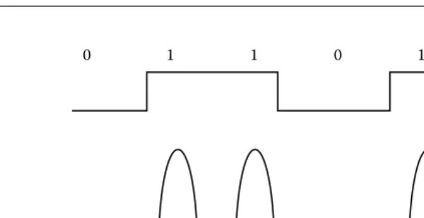
When discussing modulation, one must first focus on bits and baud and how they compare with one another. Bits, which are expressed as bit rates or typically related against time as bits per second (bps), are the measurement of data throughput. Baud is the rate of signal changes needed to send bits down a signal path. When one wants to take data and send it down a type of media such as a telephone line, it must be modulated into two different signals, which can be identified as a one (1) or zero (0). To do this, an oscillating wave is modulated by any number of techniques, such as amplitude, frequency, or phase, to create differences in the signal that can be received and returned to bits. Just like modems, wireless networks use modulation techniques to achieve communication and increase bandwidth. Looking at Figure 1.5 shows how an analog signal can be used to convey a one or zero, or vice versa.
Exploring modulation gives a good idea about how wireless networks are able to jump in bandwidth just by changing their modulation technique. It will also help us understand how wireless networks actually send information. Using modulation techniques to increase bandwidth was also seen in the rapid increase of bandwidth on modems in the late 1980s. The modem designers found better ways to modulate the data and thus increase their throughput. Before starting the modulation, one needs to make sure there is an open communication channel. A carrier signal is what is used to ensure that the communication channel is open and modulation can take place. The awful sound a modem makes is its carrier signal connecting the transmitter and the receiver together before they start modulating data.
Figure 1.5 Basic modulation.
[image:22.612.85.385.62.216.2]10 Wireless Security Handbook
1.4.1 Amplitude Modulation
Amplitude modulation (Figure 1.6) is most often recognized in AM radio. This was one of the first and most basic approaches to modulation. It works by taking the signal and applying voltage to it to indicate the presence of data. When voltage is present on the line, it means a one-bit notation or “on”; and when voltage is not on the line, it indicates a zero bit notation or “off.” Some coding mechanisms of amplitude modu-lation call out what is called a non-return to zero (NRZ); this means that if succeeding binary ones are present, the signal will continue to supply voltage for the given period of all the succeeding binary ones.
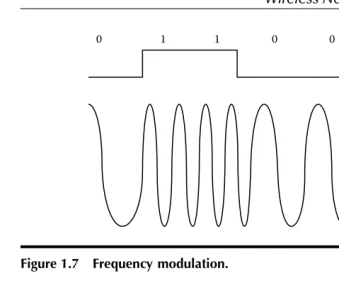
1.4.2 Frequency Modulation
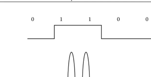
Frequency modulation (Figure 1.7), which most people use to listen to their favorite radio stations, is another modulation technique. Another name for frequency modulation is frequency shift keying (FSK); this comes from the old telegraph system wherein the operator would key in Morse code to relay a message. To understand how frequency modulation works, let us look at the old telegraph system. When an operator was waiting for a message to be sent, the key on the telegraph system was not pressed and no signal was going down the line. Once someone wanted a message to be sent, the operator would push Morse code onto the key and each time a signal would be sent down the line. This change in frequency was from no frequency to a frequency. Once the telegraph became automatic, a signal was always present; and once each key of the message was pushed, the signal changed to a higher frequency, giving us frequency
Figure 1.6 Amplitude modulation.
1
1 0
0 0 1
[image:23.612.81.385.63.218.2]1.4.3 Phase Modulation
Phase modulation is the one of the more common modulation techniques in use today. This is because it has the greatest ability to carry data when compared to the other modulation techniques we have looked at. Phase modulation has many different flavors itself. Some of these flavors incor-porate the dual use of phase modulation and the previous techniques looked at in this chapter. A basic definition of phase modulation is the process of encoding information into a carrier wave by varying its phase in accordance with a type of input signal. Looking at Figure 1.8 provides a basic understanding of this. If one looks at a carrier wave, in this case a simple sine wave, one can see that its starting point corresponds to 0°. When the wave peaks, one has 90°; as it retunes to zero, one does not call it zero, but rather 180° because it returned from 90° and one can differentiate it from a wave just starting at 0°. In addition, one can also use the negative portion of the wave. As it reaches its negative peak, one has 270°; when it returns to zero, one has 360° instead of zero because it came from the negative peak. Now, to phase this sine wave, one needs to delay the wave’s cycle. In doing this, one can see that the wave should be at 180°, when in effect it is at 270°, making it 180° out of phase.
Figure 1.7 Frequency modulation.
Figure 1.8 Phase modulation.
1
1 0
0 0 1
180°
90°
270° 360°
[image:24.612.48.387.58.350.2]12 Wireless Security Handbook
Now that we understand phase modulation, let us see how it is used to encode data. One of the simplest ways for phase modulation to encode data is called binary phase shift keying (BPSK) modulation. In this tech-nique, one uses a simple 0° phase change that equals a binary 0 and 180° phase change that equals a binary one. When the signal is sent without any phase changes, it represents a binary zero; when there is a change, one will see a 180° change in phase, which repents a binary one. This can be increased using the other degree markers such as the 90° marker and 270° marker. When all four phase change degree markers are used, one has what is called quadrature phase shift keying (QPSK). One can also introduce a more angular phase change; however, the more closely the phase change gets to another, the more difficult it is to distinguish the size of the signal’s phase change.
In direct relation to wireless networking, there are some modulation methods to look at. The first is included in the 802.11 standard and is called differential binary phase shift keying (DBPSK). This method is similar to the binary phase shift keying (BPSK) discussed above. It uses 180° of phase change to repent a binary one and 0° of binary change to repent a binary one. This means that if the data that must be sent is 0010, the wave’s signal will flow as follows. The first two zeros would be sent and no phase change would take place. Once the binary one was set to be transmitted, the phase would change to 180° out of phase. This would represent a binary one. After that, the signal would return to zero phase change, which indicates that binary zero was transmitted.
The DBPSK produced the 1-MB data rate in wireless 802.11. As we will see in Chapter 6, the 802.11 standard was capable of producing a 2-MB data rate. To achieve this, another modulation technique was used, called differential quadrature phase shift keying (DQPSK). This technique is used by a number of cellular technologies as well as the 802.11 standard. It is very much like the quadrature phase shift keying (QPSK) discussed previously. It works by having four points of reference for phase change. So, the 0, 90, 180, and 270 were used to allow encoding of more binary bits.
1.4.4 Complementary Code Keying (CCK)
Once the 802.11b standard was released, another modulation method called complementary code keying (CCK) was included to reach higher data rates. This method uses QPSK in a similar fashion, although it employs coding techniques to increase the coding. It is performed by a complex mathematical symbol structure that repents encoded binary bits. These symbols can endure extreme interference levels and have very little chance of being mistaken for each other.
1.4.5 Quadrature Amplitude Modulation (QAM)
When looking at modulation techniques, one sees the three discussed thus far in this section. Another method that has come out involves using two of these methods together. When one puts phase modulation and amplitude modulation together, one gets quadrature amplitude modulation (QAM). This is a technique in which both the phase and amplitude of a carrier wave are varied to allow for even more data bit encodings. In this, one not only has up, down, left, and right attributed to degrees and code bit, but also different levels of amplitude that allow for more bits to be encoded and sent.
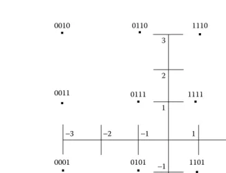
The 802.11a and 802.11g standards outlined in Chapter 6 used a
technique called orthogonal frequency division multiplexing (OFDM). Inside the OFDM standard are four types of modulation techniques: (1) binary phase shift keying (BPSK), (2) quadrature phase shift keying (QPSK), (3) 16-quadrature amplitude modulation (16-QAM), and (4) 64-quadrature amplitude modulation (64-QAM). Having discussed the first two modulation types, one can now look at the latter two: 16-QAM and 64-QAM.
Instead of using the technique discussed above, the OFDM standard took on a different approach. They used the signal constellation and broke it into four parts. Imagine an X- and Y-axis crossing to obtain a cross; inside the cross there are four distinct sections, which are used by 16-QAM to represent four subsections inside each of the original sections. This is illustrated in Figure 1.9 where one can see each of the four sections and the subsections. To change from 16-QAM to 64-QAM, one would use 6 encoded bits instead of 4 and 64 locations instead of 16. Digital television is one example of 64-QAM technology.
1.5 Wireless Groups
When discussing wireless groups, two main categories come to mind: (1) the wireless governing bodies on a national and international level, and (2) the bodies that create interoperability standards to promote standard-ization of technologies. This section outlines both of these groups and looks at how they were created, why, and what benefits they provide.
14 Wireless Security Handbook
that is globally allocated by the international groups. Reading further into this section will provide an outline of how this works and how each of these bodies works with the other to prevent radio spectrum chaos.
The wireless industry started out with vendors designing and creating their own wireless solutions. This made each network proprietary to that vendor; and if a vendor went out of business, so did any ability to get more of the needed network equipment. Wireless groups were created to make wireless technologies better able to interoperate between multiple vendors. The creation of wireless groups led to decreased time to market for new products, as well as more interoperability between vendors. These wireless groups, or standards bodies, create the main guidelines that wireless networks must follow. These groups have many internal problems that come about between what each manufacturer thinks is right; but overall, it is much better than it was before any wireless groups existed.
1.5.1 International Telecommunications Union (ITU)
The International Telecommunications Union (ITU) was formed on May 17, 1865, in Paris, France. The reasoning behind this union was to streamline the process by which telegraphs were sent internationally.
Figure 1.9 16-QAM.
0011
3 1
−3
−1
2
−2 1 2 3
−3 −2 −1
0010 0110
0111
1101
1011 1111
1001
1000 1100
1110 1110
0001 0101
0000 0100
[image:27.612.62.389.69.320.2]Before this union, each county had expended time and resources fulfilling the requirements of each independent country. The complexity of dealing with each country and each of their requirements led to a meeting to address this issue. In this meeting, which lasted two and a half months, the ITU was created. This allowed each of the participating world gov-ernments to meet and create, agree, and modify different methods of communication. This union had 20 founding members when it was first created.
On October 15, 1947, the ITU became a specialized agency under the United Nations (UN). During this time, the ITU created the International Frequency Registration Board (IFRB) to handle the task of managing the radio-frequency spectrum. This group was in charge of the Table of Frequency Allocations, which accounted for all frequency spectrum use throughout the world.
1.5.2 International Telecommunications Union Radio
Sector (ITU-R)
International Telecommunications Union Radiocommunication Sector (ITU-R) is a sub-group created by the International Telecommunications Union. The ITU-R is in charge of the technical characteristics and opera-tional procedures of all wireless services. As part of its charter, the ITU-R develops and maintains the ITU-Radio ITU-Regulations. This regulation serves as a binding international treaty that governs the use of the radio spectrum for all of its members worldwide.
One of the key documents that the ITU-R is in charge of is the Radio Regulations. This document is a subsection of The International Frequency Registration Board’s Table of Frequency Allocations. The Radio Regulations were created in 1906 in Berlin, Germany, and address the frequencies ranging from 9 kHz to 400 GHz in the Table of Frequency Allocations. Today this document contains more than 1000 pages detailing how the spectrum can be used and shared around the globe. Making changes to this document is only allowed at a world radiocommunication conference such as the World Administrative Radio Council (WARC). During this event, members discuss, create, and ratify definitions for frequency allocation.
1.5.3 Federal Communications Commission (FCC)
16 Wireless Security Handbook
section of the FCC that deals with wireless technologies is the Wireless Telecommunications Bureau (WTB). Its service includes cellular telephone, paging, personal communications services, public safety, and other com-mercial and private radio services. The WTB is also the bidding authority for spectrum auctions.
The main goals of the Federal Communications Commission’s Wireless Telecommunications Bureau are to:
Foster competition among different services
Promote universal service, public safety, and service to individuals with disabilities
Maximize efficient use of spectrum
Develop a framework for analyzing market conditions for wireless
services
Minimize regulation, where appropriate
Facilitate innovative service and product offerings, particularly by small businesses and new entrants
Serve WTB customers efficiently (including improving licensing,
eliminating backlogs, disseminating information, and making staff accessible)
Enhance consumer outreach and protection and improve the
enforcement process
1.5.4 Conference of European Post and
Telecommunications (CEPT)
The European Conference of Postal and Telecommunications Administra-tions — CEPT — was established in 1959. At that time, only 19 countries were involved. As the CEPT gained momentum, it was able to expand into 26 countries within its first 10 years. After 29 years of operation, the CEPT organization decided to create the ETSI, the European Telecommu-nications Standards Institute. The ETSI was created to handle standardiza-tion and not regulatory issues such as spectrum allocastandardiza-tion.
To get a better understanding of the CEPT and ETSI, one can compare them to the United States and its creation of the Federal Communications Commission (FCC) agency and the Institute of Electrical and Electronics Engineers (IEEE). The FCC manages issues concerning spectrum allocation and power regulations inside each allocated spectrum. The IEEE builds standards for devices that can operate in one of the allocated spectrums. The members of the CEPT as of September 21, 2004, are listed as follows:
Albania, Andorra, Austria, Azerbaijan, Belarus, Belgium, Bosnia and Herzegovina, Bulgaria, Croatia, Cyprus, Czech Republic, Denmark, Estonia, Finland, France, Germany, Great Britain, Greece, Hungary, Iceland, Ireland, Italy, Latvia, Liechtenstein, Lithuania, Luxembourg, Malta, Moldova, Monaco, The Nether-lands, Norway, Poland, Portugal, Romania, Russian Federation, San Marino, Serbia and Montenegro, Slovakia, Slovenia, Spain, Sweden, Switzerland, the former Yugoslav Republic of Mace-donia, Turkey, Ukraine, Vatican
1.5.5 Wi-Fi Alliance
The Wi-Fi Alliance is a nonprofit international association formed in 1999. Its main goal is to certify the interoperability of wireless local area network (LAN) products based on the IEEE 802.11 specification. Wi-Fi stands for wireless fidelity. The Wi-Fi Alliance has certified more than 1000 products with its Wi-Fi® certification. This association came about due to the lack
of well-defined technical areas in the 802.11 standard. As seen later in this book, most of the wireless standards lack certain details. For example, the 802.11 standard states that roaming will be supported, although it does not detail how a manufacturer should allow for roaming. This means that the Wi-Fi Alliance will only certify products to what is defined in the standard. The security mechanism called WEP only started as a 40-bit key in the original 802.11b standard. In the security section of this book, one sees that the key size of WEP was increased to 104 bits; this was done outside the IEEE standard. This means that for the Wi-Fi Alliance to certify a product, it only has to support a 40-bit key rather than the more often recommended 104-bit key. The Wi-Fi Alliance’s goal was to make sure that if a product is Wi-Fi certified that it would interoperate with other Wi-Fi-certified products. The original name of the Wi-Fi Alliance was the Wireless Ethernet Compatibility Alliance (WECA).
1.5.6 IEEE
18 Wireless Security Handbook
of them arranging two different meetings with each other for very similar objectives, they decided to merge the two organizations. Many brilliant minds, including Thomas Edison, were part of the AIEE, which is now known as the IEEE.
The IEEE is a governing body that created the 802 standards for network communications. The requirements needed to create an IEEE standard have a well-defined process that has seven layers. These layers allow the standard to move from thought to a written, defined, and approved IEEE standard. The seven-step process is outlined as follows:
1. Call for interest 2. Study group 3. Task group
4. Working group ballot 5. Sponsor ballot
6. Standards board approval 7. Publication
The process starts out with a call for interest in which the IEEE kicks off a meeting about a peculiar standard. In our case, this would most likely be a new wireless standard. The IEEE has a large scope, well over the small wireless subsection that relates to our example. Once the call for interest has been performed, a meeting will take place. In this meeting, attendees discuss the need for this type of standard and whether or not it is even needed. Depending on how they react to this initial meeting, the IEEE can continue with this standard or can stop it here. If they decide to continue, the next step is to develop a study group of participants to look into this further. This group would work together to discuss and decide if they are willing to commit to the next phase, in which a standard will be drafted. Once the study group moves to the task group, they are going to start writing the standard draft. Once the draft is finished, it will need to go to a working group ballot. At this point, the standard must receive a 75 percent approval rate until it can move to the next step. Most of the time, many drafts are created in this phase until one finally receives the required votes. This is when the most disagreement and time-con-suming discussion takes place. Frequently, this is because each vendor involved with a particular standard has already invested R&D dollars into something that another group member may want to change. This political battle takes place until a vote reaches the 75 percent mark needed to move to the next step. After the vote meets the 75 percent mark, it goes through another ballot in which executive members of the IEEE vote on it. After this phase, it goes to the IEEE to approve and publish.
1.6 Chapter 1 Review Questions
1. What happens to an 802.11b wireless signal when an evergreen tree is located between the transmitter and receiver?
a. Nothing. b. It is refracted. c. It is diffracted. d. It is reflected. e. It is absorbed.
2. What are the two correct terms used to measure antenna gain? a. dBi and DBd
b. Watts and milliwatt c. dBd and dBi d. EIRP
3. The designator dBi is a decibel compared to what? a. Milliwatt
b. Decibel
c. Isotropic radiator d. RADIUS
4. What does RF stand for?
5. Which type of modulation does 802.11b use? a. QAM
b. FM c. AM d. CCK
6. How can one send more data across the air? a. Increase the transmit power.
b. Use a more complex modulation. c. Use a bigger antenna.
d. Use a wider frequency band.
7. What was the Wi-Fi Alliance formerly known as? a. FCC
20 Wireless Security Handbook
8. What seal certifies interoperability in a manufacturer’s wireless device?
a. WHY b. Hi-Fi c. WECA
d. Wi-Fi Certified e. Wi-Ki
9. Which wave will travel the greatest distance? a. FM radio
b. X-ray c. 802.11a d. Microwave
10. What two items should be maintained near the edges of a wireless cell when performing a site survey?
a. High signal-to-noise ratio b. Low signal-to-noise ratio c. High noise level
d. High signal strength
11. What would the FCC and ETSI regulate on a wireless network? (Select more than one)
a. Power outputs b. Total client number
c. Channel number and frequency d. Who can use the system
12. What bandwidth term is this phrase stating? On any given day, my wireless network has a low bandwidth of ______.
a. 11 Mbps b. 2.4 GHz c. 11 MHz d. 5.4 GHz
13. Which of the following show the correct use of a wireless network? a. Using wireless to connect two buildings point-to-point
b. Mobile access from laptop or PDA c. As a way to connect a server
d. To increase bandwidth on a 10/100 wired network
b. Reflection c. Diffraction d. Scattering
15. When performing wireless power calculations, what two terms are often converted into each other?
a. dBi to dBi b. dB to Watts c. dBm to DBi d. dBd to dBi
16. What standards body creates wireless standards? a. Wi-Fi Alliance
b. IEEE c. FCC d. WECA
17. What key size is required in WEP for the Wi-Fi Alliance to certify a product?
a. 40 bits b. 120 bits c. 128 bits d. 56 bits
18. What does Wi-Fi stand for?
a. Wireless infrastructure fidelity industry b. Wireless Interoperability Forum Institute c. Wireless fidelity
Chapter 2
Risks and Threats
of Wireless
This chapter discusses the general goals for information security and how they are used to measure risk and understand threats. This information will help in the next sections of this chapter where each of the threats relating to the many types of wireless communications is explored. After looking at each of the threats, this chapter focuses attention on wireless hackers. In this chapter, we see how hackers locate the existence of wireless networks as well as how law enforcement tracks down these hackers.
2.1 Goals of Information Security
When looking at information security, one must address the three tenets of information security: (1) confidentiality, (2) availability, and (3) integrity. These long-standing goals will help us understand what we are trying to protect and why. This information will help when one starts looking at all the risks and threats that face wireless communications. Before one can properly evaluate risk, one needs to set a baseline to understand the definition of each goal one is trying to uphold.
2.1.1 Confidentiality
Attacks on the confidentiality of information relate to the theft or unau-thorized viewing of data. This can happen in many ways, such as the interception of data while in transit or simply the theft of equipment on which the data might reside. The goal of compromising confidentiality is to obtain proprietary information, user credentials, trade secrets, financial or healthcare records, or any other type of sensitive information.
Attacks on the confidentiality of wireless transmissions are created by the simple act of analyzing a signal traveling through the air. All wireless signals traveling through the air are susceptible to analysis. This means there is no way to have total confidentially because one can still see a signal and subsequently record it. The use of encryption can help reduce this risk to an acceptable level. The use of encryption has its own flaws, as seen later in this book. For the most part, the encryption is secure itself, although how it is implemented and how key management is handled may produce flaws that are easily exploited.
2.1.2 Availability
Availability is allowing legitimate users access to confidential information after they have been properly authenticated. When availability is compro-mised, the access is denied for legitimate users because of malicious activity such as the denial-of-service (DoS) attack.
Receiving RF signals is not always possible, especially if someone does not want you to. Using a signal jammer to jam an RF signal is a huge problem that has been facing national governments for years. Looking for the availability of RF local area networks (LANs), one notices that per-forming a DoS attack is easy to accomplish. This is due to the low transmit power allocated by the U.S. Government and poor frame management techniques included in most of the current day wireless standards.
2.1.3 Integrity
Integrity involves the unauthorized modification of information. This could mean modifying information while in transit or while being stored elec-tronically or via some type of media. To protect the integrity of information, one must employ a validation technique. This technique can be in the form of a checksum, an integrity check, or a digital signature.
Risks and Threats of Wireless 25
This could trick the receiving party into thinking that a confidential exchange of data is taking place when in fact it is the exact opposite. Wireless networks have adapted to this type of threat over time. One can see this advancement as new security standards emerge, creating increas-ingly complex integrity checks.
2.2 Analysis
Analysis is the viewing, recording, or eavesdropping of a signal that is not intended for the party who is performing the analysis. All RF signals are prone to eavesdropping; this is because the signal travels across the air. This means anyone within the signal’s path can hear the signal. One of the only protections available to prevent the loss of confidentiality is encryption. If a signal is using encryption, then its confidentiality can be upheld until that form of encryption is defeated. The risk of analysis on an RF signal is an inherent risk that cannot be avoided. The only option is to mitigate the risk with some type of confidentiality control.
2.3 Spoofing
Spoofing is the act of impersonating an authorized client, device, or user to gain access to a resource that is protected by some form of authenti-cation or authorization. When spoofing occurs in wireless networks, it primarily involves an attacker setting up a fake access point to get a valid client to pass authentication information to that attacker. Another way attackers spoof is by performing a man-in-the-middle attack. In this scenario, an attacker would position himself between a client and the network. This could be accomplished by spoofing a valid access point or by hijacking a session. Once this part is complete, the attacker would then use the authentication information provided by the client and forward it to the network as if it originally came from the attacker.
2.4 Denial-of-Service
Denial-of-service (DoS) is the effect of an attack that renders a network device or entire network unable to communicate. Hackers have found that certain crafted packets will make a network device unresponsive, reboot, or lock up. They have used this technique to shut down high-traffic networks and Web sites. They have also used this attack to reboot network equipment in an attempt to pass traffic through the device as it
is booting up. This is done to try to circumvent any policies set up on the device to protect it or devices behind it. The DoS threat can also adversely affect the availability of a network or network device.
Wireless DoS attacks can be achieved with small signal jammers. Finding signal jammers is not as difficult as one might think. Some modern-day wireless test equipment can perform jamming. This is not the tool’s intended purpose, although it is commonly used for this. Jamming is possible because the government regulates the amount of power allowed on a wireless network. In relation to wireless LANs, the amount of power used is a very small amount. This means that it is not difficult to overpower an existing device with a home-made one.
Another DoS threat relating to LANs in particular is the poor structure of management frames. These frames allow for anyone who can analyze the wireless signals to perform a DoS attack by replaying certain man-agement frames. Mostly, theses attacks are layer two frame attacks. These attacks try to spoof management traffic, informing the client that he is no longer allowed to stay connected to the network. Chapter 13 discusses these attacks in more detail.
2.5 Malicious Code
Malicious code can infect and corrupt network devices. Malicious code comes in many forms: viruses, worms, and Trojan horses. People often confuse the three main forms of malicious code. Because of this, they use these terms interchangeably. This section looks at each of these and identifies what classifies them into each of the three groups. Viruses infect devices and do not have the ability to replicate or spread outside the infected system on their own. Once a virus infects a machine, it can only replicate inside the infected machine. This means that all threats from viruses stem from receiving infection. The threat of worms is much higher because they can spread across the enterprise and out to the Internet, infecting multiple devices. In the past few years, humans have started to see global worms that propagate across the entire world. The final mali-cious code threat discussed here is the Trojan horse. This threat comes from installing or running programs that can have or within their use execute code that might contain malicious content.
Risks and Threats of Wireless 27
Another form of malicious content relating to wireless is spam.
Although spam is not destructive in nature, the time and money it costs an organization often makes it seen as malicious. Spam is not just related to wireless. Long before wireless spam there was e-mail spam. Today’s wireless devices are capable of receiving messages in many formats: e-mail, text messaging, instant messaging, and voice calls. All of these are starting to see spam pop up on them. Dealing with spam has created a security market of its own with products, solutions, and services created to combat this threat.
2.6 Social Engineering
Social engineering is the often called low-tech hacking. It involves some-one using the weakness of humans and corporate policies to obtain access to resources. Social engineering is best defined as tricking or manipulating a person into thinking the party on the phone is allowed access to information, which they are not. The threat of social engineering has been around for quite some time. Some of the most well-known computer hackers used this type of attack to get information. The real threat to this is the skill level involved. No one needs to be computer savvy or a technical genius to perform this type of attack. There are a number of things to do to prevent this type of attack. First, make sure that a policy is in place regarding sensitive information and phone usage. Make sure that not anyone can call and reset someone’s password. Create a help-desk identification process to authenticate callers to the help-help-desk operators.
2.7 Rogue
Access Points
Rogue access points pose a major threat to any organization. This is because of the high availability and the limited security features of off-the-shelf access points. If a company does not appr oach the WLAN (wireless local area network) concept fast enough, frustrated employees will take it upon themselves to start the process. When this happens, employees often put in wireless systems of their own. Even with most current-day access points supporting advanced security standards, the default configuration of an out-of-the-box access point is set to the least secure method. This has created a real threat because now a user can easily bring in a rogue access point, plug it in, and put the entire network at risk. The knowledge level required to install an off-the-shelf access point has almost become plug-and-play today. This means that more and more people have the ability to place rogue access points. These same
people lack the ability to secure these devices or even understand the risk they are posing for the company.
Most access points come from employees, although as we will learn later there are cases where an attacker would try to set one up for easy return access. This was not a big issue until recently when the price of 802.11b access points fell well below $100. To do this, an attacker would need physical access and a network port. If a hacker wanted access bad enough, spending $100 for it would be a conceivable expense.
With companies investing in stronger security mechanisms, it would be a shame to have an incident in which an attacker gains access through a non-secure rogue access point. Because of the threats associated with rogue access points many companies have started to put controls in place to increase awareness and prevent the deployment of rogue access points. Many companies that jumped into the newly formed wireless security market have adapted and created tools to detect rogue access points. Some companies have handled rogue access points by creating policies about wireless usage and strict penalties for rogue access placement. Others have taken a second route and invested in wireless intrusion detection systems (WIDS) software.
2.8 Cell Phone Security
Now we will have a discussion of general cell phone identification and security. Cell phones have had a slight advantage over other types of wireless communications in the security realm. This is due to their over-whelming numbers. Most people today have a cell phone; and with so many people using cell phones, many security risks and subsequent controls have been developed to counter each other. Understanding this information will show how cellular phone providers have mitigated similar risks that face wireless local area networks.
Cell phones send radio frequency (RF) transmissions on two distinct channels: (1) one for actual voice communication and (2) the other for control signals. This control signal identifies itself to a cell site by broad-casting its mobile identification number (MIN) and electronic serial number (ESN). When the cell tower receives the MIN and ESN, it determines if the requester is a legitimate user by comparing the two numbers to a cellular provider’s subscription database. Once the cellular provider has acknowledged that the MIN and ESN belong to one of its customers, it sends a control signal to permit the subscriber to place calls.
Risks and Threats of Wireless 29
ability to reprogram phones, transforming them into advanced micro-phones capable of recording and transmitting sound from their location to anywhere in the world.
Monitoring calls is an easy task, especially for phones that use analog technology. This is because most analog cell phone technologies were transmitted in the same band as FM radio. A commonly available radio frequency scanner could get one up and listening to calls in minutes. With the proliferation of digital cellular networks, more and more security was erected. This was great because inside a service provider’s network, your calls were, for the most part, safe. There were easier analog targets for criminals to exploit. One’s digital phone was not so safe if one roamed or went outside of a provider’s area of coverage. When two cellular providers wanted to hand off calls to each other for billing purposes, they converted them to analog so they had a common protocol for interoper-ability. This also meant that security was no longer present. So, even with a digital phone, once the MIN and ESN are removed or identified from the phone call, it could still be tracked, cloned, or monitored inside the digital network.
Another trick involves turning a cellular telephone into a microphone and transmitter. This can be used to record a conversation or bug a room. This can be done without your knowledge by police, governments, and even some highly educated people. How does it work? It is easy to do, just send a maintenance command on the control channel to the phone. This command places the cellular telephone in a diagnostic mode. When this is done, conversations in the immediate area of the telephone can be monitored over the voice channel. The signal engages the phone to perform this monitoring action without any indication of it taking place. The user does not know the telephone is in the diagnostic mode and transmitting all nearby sounds until he or she tries to place a call. The calling feature does not work and the phone is useless until the power is cycled. After that, the phone returns to a normal state as if nothing ever happened.
This is very scary because the user has no idea he is bugged by his own phone through the airwaves. This threat is the reason why cellular telephones are often prohibited where classified or sensitive discussions are taking place. Someone could be bugging your phone as you read. Do not worry; as long as one can place a call without cycling the power, you’re ok.
One publicized case of cell phone monitoring involved former Speaker of the House of Representatives, Newt Gingrich. A call between Gingrich and other Republican leaders was monitored and taped. The conversation concerned Republican strategies for responding to an ethics violation for which Gingrich was being investigated. This call was given, or most likely sold, to the New York Times and made public.