Behaviour of Glass FRP Composite Tubes
Under Repeated Impact for Piling Application
By
Ernesto Jusayan Guades
Supervised by
Prof. Thiru Aravinthan
Dr. Mainul Islam
A dissertation submitted for the award of
DOCTOR OF PHILOSOPHY
Centre of Excellence in Engineered Fibre Composites
Faculty of Engineering and Surveying
University of Southern Queensland
Toowoomba, Queensland, Australia
Abstract
Fibre composites have been a viable option in replacing traditional pile materials
such as concrete, steel and timber in harsh environmental conditions. On the other
hand, the emergence of fibre reinforced polymer (FRP) composite tubes as a
structural component and their corrosion-resistant characteristics made these
materials potential in piling application. Driving these piles, however, requires more
careful consideration due to their relatively low stiffness and thin walls. The
possibility of damaging the fibre composite materials during the process of impact
driving is always a concern. Research has therefore focused in understanding the
impact behaviour of these materials in order for them to be safely and effectively
driven into the ground.
This study investigated the behaviour of composite tubes subjected by
repeated axial impact. The effects of impact event (incident energy and number of
impact) on the instantaneous response and the residual properties of composite tubes
were examined. Tubes made of glass/vinyl ester, glass/polyester, and glass/epoxy
materials of different cross sections were considered. The impact behaviour of the
tubes was experimentally and analytically investigated.
An experimental study on the repeated impact behaviour of square composite
tube was conducted. The result showed that the dominant failure mode of the tube
repeatedly impacted was characterised by progressive crushing at the upper end. This
failure was manifested by inter and intra laminar cracking and glass fibre ruptures
with simultaneous development of axial splits along its corners. It was found that the
drop mass and impact velocity (or drop height) have pronounced effects on the
collapse of the tubes at lower incident energies. Their effects, however, gradually
decrease at relatively higher energies. The result also indicated that the incident
energy is the major damage factor in the failure of tubes for lower number of
impacts. On the contrary, the number of impacts becomes the key reason as soon as
the value of incident energy decreases.
The effects of the damage factors such as the level of impact energy, the
impact repetitions, and the mass impactor on the residual (post-impact) properties
were also examined. The result of the investigation revealed that these factors
significantly influenced the residual strength degradation of the impacted tubes. In
damage brought by them is localised in most of the cases. The maximum reduction
on the residual moduli is roughly 5%. On the other hand, the residual strengths
degraded by up to 10%. The flexural strength of the tube was the most severely
affected by the impact damage than its compressive and tensile strengths. This result
was due to the fact that the impact damage on matrix and fibre both contributed on
the flexural strength degradation. Moreover, the presence of matrix cracks or
delamination lead to an increase in buckling instability during the flexural test,
resulting to a much higher degradation compared to the other strengths. The
comparison of the residual compressive strengths sourced at different locations along
the height of the tube revealed that the strength reduction varied with its location.
The degradation of the compressive strength of the impacted tube decreased when its
location from the top of the tube increased. This result indicated that the influence of
impact damage on the degradation of residual compressive strength of the tube is
concentrated only in region closer to the impact point.
Finally, theoretical prediction using the basic energy principle was performed
to gain additional understanding on the damage evolution behaviour of composite
tubes subjected by repeated axial impact. The damage evolution model was verified
through experimental investigation on a 100 mm square pultruded tube. The model
was applied to composite tubes of different cross sections and materials made from
vinyl ester/polyester/epoxy matrix reinforced with glass fibres. It was found that the
experimental results on a 100 mm square pultruded tube and the proposed damage
model agreed well with each other. The variation is less than 10% indicating that the
model predicted reasonably the damage evolution of the tube subjected by repeated
impact loading. It was also found that the energies describing the low cycle, high
cycle, and endurance fatigue regions of the composite tubes are largely dependent on
their corresponding critical energy Ec. The higher the Ec values, the higher the range
of energies characterising these regions. The repeated impact curves (or Ec) of tubes
made from glass/epoxy is higher compared to the other matrix materials. Similarly,
circular tubes have greater Ec values of comparable square and rectangular tubes.
From this study, an improved understanding of the behaviour of glass fibre
FRP composite tubes under repeated axial impact can be achieved. The information
provided in this study will help in developing efficient techniques and guidelines in
Certification of Dissertation
I certify that the ideas, experimental work, results, analysis and conclusions reported
in this dissertation are entirely my own effort, except where otherwise
acknowledged. I also certify that the work is original and has not been previously
submitted for any award, except where otherwise acknowledged.
/ /
Signature of Candidate
Endorsed:
/ /
Signature of Supervisor/s
/ /
Acknowledgements
With humble gratitude I must acknowledge the following that have in one way or the
other contributed to the successful completion of this dissertation.
Prof. Thiru Aravinthan, my Principal Supervisor, for giving me the
opportunity to do a PhD at the University of Southern Queensland (USQ). I am
grateful to him for coaching me and willingly providing invaluable input and
direction. I learned a great deal of things from him in my entire journey of PhD. I am
also indebted to Dr. Mainul Islam, my Associate Supervisor, for sharing his time and
ideas to make this dissertation a success. I greatly appreciate Dr. Allan Manalo for
his support in my application to study at USQ. His technical suggestions and
assistance were indispensable in improving the quality of this research. The
generosity he extended to me during my study is greatly appreciated.
I would like to acknowledge the people behind USQ who provided the Post
graduate Scholarship Grant. I thank the supports of the Faculty of Engineering and
Surveying and the Centre of Excellence in Engineered Fibre Composites (CEEFC)
for making this research possible. My thanks to Assoc. Prof. Karu Karunasena, Dr.
Jay Epaarachchi, Dr. Francisco Cardona for all the useful discussions and
suggestions. I owe an appreciation for the technical and administrative support from
Martin Geach, Wayne Crowell, Atul Sakhiya, and Mohan Trada. Thanks to CEEFC
staff and postgraduate students for the support and friendship. I especially thank
Michael Kemp and all the staff of Wagners Composite Fibre Technology for
providing the precious test samples. Thanks are expressed to the administration and
staff of Northwest Samar State University for the Study Grant that would pave the
way for my travel to Australia in pursuit of another academic achievement.
My unending recognition to Myla, who always, in all ways, was there for me.
I am grateful to her for unselfishly setting aside her personal needs to give way to my
personal dreams and aspiration. Very special thanks to my family who have been a
source of encouragement and inspiration throughout my life. My appreciation to the
Inocentes family, Jen, and the Filipino community of Toowoomba for welcoming me
into their homes. Their incredible hospitality and generosity helped me overcome my
homesickness. Above all, I am thanking the Almighty God for guiding me all
throughout this endeavour. To those whom I missed to mention but have been a great
Associated Publications
Journal
1. E.J. Guades, T. Aravinthan. M.M. Islam, and A.C. Manalo (2012). A review on the driving performance of FRP composite piles. Composite Structures, Volume 94, May issue , p 1932-1942.
http://www.sciencedirect.com/science/article/pii/S0263822312000451
2. E.J. Guades, T. Aravinthan, A.C. Manalo, and M.M. Islam (2013). Experimental investigation on the behaviour of square FRP composite tubes
under repeated axial impact. Composite Structures, Volume 97, March issue,
p 211-221.
http://www.sciencedirect.com/science/article/pii/S0263822312005296
3. E.J. Guades and T. Aravinthan (2013). Residual properties of square FRP composite tubes subjected to repeated axial impact. Composite Structures, Volume 95, January issue, p 354-365.
http://www.sciencedirect.com/science/article/pii/S0263822312004072
4. E.J. Guades, T. Aravinthan, A.C. Manalo, and M.M. Islam (2013). Damage modelling of repeatedly impacted square fibre-reinforced polymer composite tube. Journal of Materials and Design, Volume 47, May issue, p 687-697. http://www.sciencedirect.com/science/article/pii/S0261306912008801
Conference Papers/Poster Presentation
1. E.J. Guades, T. Aravinthan. M.M. Islam, and A.C. Manalo (2012). Effects of energy levels on the impact fatigue behaviour and post-impact flexural
properties of square FRP pultruded tubes. Proceedings of the 22nd
Australasian Conference on th Mechanics of Structures and Materials (ACMSM22), 11-14 December, Sydney, New South Wales, Australia.
2. E.J. Guades, T. Aravinthan. M.M. Islam, and A.C. Manalo (2012). Stiffness
degradation of FRP pultruded tubes under repeated axial impacts.
Proceedings of the 3rd Asia-Pacific Conference on FRP in Structures, February 2- 4, Hokkaido, Japan. Paper no F1B05.
3. E.J. Guades, T. Aravinthan, and M.M. Islam. (2011). Driveability of composite piles. Proceedings of the 1st International Postgraduate Conference on Engineering, Designing and Developing the Built Environment for Sustainable Wellbeing, April 27-29, QUT, Brisbane, Australia. p. 237-242
5. E.J. Guades, C. S. Sirimanna, T. Aravinthan & M.M. Islam. (2010). Behaviour of composite pile under axial compression load. Proceedings of the 22nd Australasian Conference on the Mechanics of Structures and Materials (ACMSM21), December 7-10, Melbourne, Australia. p. 457-462.
6. E.J. Guades, T. Aravinthan, and M.M. Islam (2011). Impact behavior of pultruded tubes as hollow FRP piles. Poster presentation during the USQ Community Engaged Research Evening. November 15, Sacred Heart Church Function Room, Towoomba, Queensland, Australia.
Table of Contents
List of figures xii
List of tables xvii
Notations xx Chapter 1 Introduction 1.1 General……….. 1
1.2 Background……….. …….... 1
1.3 Fibre composites as an alternative in piling applications……….. 2
1.4 FRP tubes as composite piles………. 4
1.5 Challenges in using hollow FRP pipe piles……..………. 5
1.6 Research needs related to their driving performance………… 6
1.7 Objectives……… 7
1.8 Scope of the thesis.……….. 8
1.9 Outline of the thesis……… 9
1.10 Summary……….. 10
Chapter 2 Review of composite piles and their driving performance 2.1 General………... 11
2.2 Types of composite piles……… 11
2.2.1 Steel pipe core piles……….. 11
2.2.2 Structurally reinforced plastic piles……….. 12
2.2.3 Concrete-filled FRP pipe piles……….. 13
2.2.4 Fibreglass pultruded piles………. 14
2.2.5 Fibreglass reinforced plastic piles………. 15
2.2.6 Hollow FRP pipe piles……….. 16
2.2.7 FRP sheet piles……….. 17
2.3 Driving performance of composite piles……….... 18
2.3.1 Types of driving hammer and its effect……… 18
2.3.2 Resistance to driving offered by the soil……….. 20
2.3.3 The ability of the pile to transfer driving stresses……….. 23
2.3.4 Strength of the pile to resist driving stresses………… 25
2.4 Recent developments on hollow FRP pipe piles……… 30
2.5 Study on the impact behaviour of FRP composite tubes as a research needs……… 35
2.6 Behaviour of FRP composite plates/laminates repeatedly impacted or tubes under repeated transverse impact…….. ………35
Chapter 3 Characterisation of the properties of composite tubes
3.1 General………... 41
3.2 Composite tubes under study………. 41
3.3 Manufacturing of tubes using pultrusion process……….. ……... 42
3.4 Glass fibre content……….. 43
3.5 Coupon tests………... 45
3.5.1 Compressive test………... 45
3.5.2 Tensile test……… 47
3.5.3 Flexural test………... 49
3.6 Full scale tests……… 51
3.6.1 Compressive test. ………. 51
3.6.2 Flexural test………... 54
3.7 Finite element (FE) analysis on full scale specimen ………. 59
3.7.1 FE simulation on the compressive behaviour. ……… 60
3.7.2 FE simulation on the flexural behaviour. ……… 63
3.8 Summary of the mechanical properties of composite tubes…….. 69
3.9 Conclusions……… 71
Chapter 4 Investigation on the behaviour of square FRP composite tubes under repeated axial impact 4.1 Introduction……… 72
4.2 Experimental program……… 73
4.2.1 Test specimen………73
4.2.2 Test set-up and procedure………. ………73
4.2.3 Data processing………. ………78
4.3 Experimental results and discussion……….. 80
4.3.1 Mode of damage………... 80
4.3.2 Progressive failure pattern……… 80
4.3.3 Impact load………83
4.3.4 Impact energy………87
4.3.5 Impact damage tolerance limit……….. 92
4.4 Conclusions ………... 96
Chapter 5 Residual properties of square FRP composite tubes subjected to repeated axial impact 5.1 Introduction……… 98
5.2 Experimental program……… 99
5.2.1 Test specimen and repeated impact testing ………….. 99
5.2.2 Residual properties testing ………... 101
5.3 Experimental results and discussion……….. 106
5.3.1 Mode of damage………... 106
5.3.3 Effects of impact energy………... 108
5.3.4 Effects of impact repetitions ……….…………... 112
5.3.5 Effects of mass of the impactor……… 116
5.3.6 Comparison between compressive, tensile and flexural properties……….. 120
5.3.7 Residual strength versus modulus………. 122
5.3.8 Variations of residual compressive strength with the height of the tube……… 124
5.4 Conclusions……… 125
Chapter 6 Damage modelling of repeatedly impacted FRP composite tube 6.1 Introduction……… 128
6.2 Theoretical prediction methods………. 128
6.3 Quasi-static compressive test………. 131
6.3.1 Specimen and testing……… 131
6.4 Repeated impact test results………... 132
6.5 Evaluation of damage using parameter D……….. 134
6.6 Proposed damage response model……….. 134
6.6.1 Minimum number of impacts to failure of the tube, Nf ….……….. 136
6.6.2 Minimum incident energy to fail the tube for one impact (critical energy), Ec ……… 136
6.6.3 Determination of (Ec)Quasi-static using quasi-static compressive test……… 138
6.6.4 Solving b value………...……….. 140
6.7 Comparison with the experimental data………. 141
6.7.1 Verification of the repeated impact curve………. 141
6.7.2 Validation of the proposed model………. 142
6.8 Summary of procedure in establishing the damage evolution curve ………..……… 144
6.9 Application of the model to FRP composite tubes with square and rectangular cross sections ……… ……... 146
6.9.1 Square and rectangular FRP composite tubes... ……... 146
6.10 Conclusions……….. 153
Chapter 7 Application of the damage evolution model to other types of composite tubes 7.1 Introduction………... 155
7.2 Background on the constituents of composite tubes used in the model………... 156
7.2.1 Vinyl ester resin……… 156
7.2.2 Polyester resin………157
7.3 Glass/vinyl ester composite tubes……….. 158 7.4 Glass/polyester composite tubes……… 163 7.5 Glass/epoxy composite tubes………. 170 7.6 Discussion on the repeated impact and damage evolution
curves of FRP composite tubes………... 176 7.7 Discussion on the application of FRP composite tubes in
piling system ……….. 178 7.8 Conclusions……… 181
Chapter 8 Conclusions
8.1 Summary……… 182 8.2 Main conclusions from the study………... 182
8.2.1 Behaviour of composite tubes subjected by impact loading……….. 182 8.2.2 Effects of impact loading on the residual
properties of composite tubes………... 183 8.2.3 Prediction on the damage evolution of
composite tubes………. ……... 184 8.3 Recommendations for future study……… 185
References 186
Appendix A Summary of results of the coupon and full scale tests on CT1 and CT2 specimens
A.1 Fibre fraction test……….. A-1 A.2 Compressive test on coupon specimen………. A-2 A.3 Tensile test on coupon specimen……….. A-3 A.4 Flexural test on coupon specimen………. A-5 A.5 Compressive test on full scale specimen……….. A-7 A.6 Flexural test on full scale specimen……….. A-9
Appendix B Summary of specimen dimension and snapshots of the machine/apparatus used in repeated impact test
B.1 Summary on the details of the specimens………. B-1 B.2 Repeated impact testing set-up and specimen snapshots………. B-3 B.3 Apparatus used in the micro observation of damage……… B-4
Appendix C Variation of acceleration data and impact stress with the height of the tube
Appendix D Summary of specimen dimension and results in residual properties testing
List of Figures
Chapter 1 Introduction
Figure Figure caption Page
1.1 Problems of traditional piles installed in harsh environments 2
Chapter 2 Review of composite piles and their driving performance
Figure Figure caption Page
2.1 Steel pipe core piles……… 12
2.2 Structurally reinforced plastic piles……… 13
2.3 Concrete-filled FRP pipe piles……… 14
2.4 Fibreglass pultruded piles……… 15
2.5 Fibreglass reinforced plastic piles……….. 16
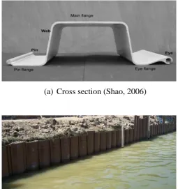
2.6 Geometry of hollow FRP pipe piles used in the application……….. 16
2.7 FRP sheet piles……… 17
2.8 Condition of the composite piles after driving……… 26
2.9 Condition of the composite piles after driving……… 27
2.10 Composite pile installed in Route 40 Bridge……….. 28
2.11 Composite piles driven near Route 351 Bridge………. 29
2.12 Hollow FRP pipe piles replacing deteriorated timber piles……… 31
2.13 Pultruded composite tubes used in shoring-up boardwalks……… 32
2.14 Impact driving of 125 mm square pultruded tubes………. 33
2.15 Impact driving of 475 mm diameter hollow FRP pipe pile……… 34
Chapter 3 Characterisation of the properties of composite tubes Figure Figure caption Page 3.1 Oblique view of the composite tubes……….. 42
3.2 The basic pultrusion process concept………. 43
3.3 Coupon specimens and residue showing the fibre glass orientation…….. 44
3.4 Compressive test set-up on coupons……….. 46
3.5 Compressive stress-strain relationship……… 47
3.6 Compressive failure mode and condition of the specimens after the test… 47 3.7 Tensile test set-up on coupons……… 48
3.8 Tensile stress-strain relationship………. 49
3.9 Tensile failure mode and condition of the specimens after the test……… 49
3.10 Flexural test set-up on coupons………... 50
3.11 Flexural stress-strain relationship……… 51
3.12 Flexural failure mode and condition of the specimens after the test…….. 51
3.13 Compressive test set-up on full scale specimens……… 52
3.14 Compressive stress-strain relationship of full scale specimens………….. 53
3.15 Compressive failure mode and condition of the full scale specimens…… 54
3.16 Flexural test on full scale specimens……….. 55
3.17 Flexural load-displacement relationship (3-point bending test)…………. 56
3.18 Flexural load-strain relationship (3-point bending test)……….…………. 57
3.19 Typical failure modes for in 3-point bending tests………..……… 57
3.20 Flexural load-displacement relationship (4-point bending test)…..……… 58
3.21 Flexural load-strain relationships (4-point bending test)…...………. 59
3.22 Typical failure modes for in 3-point bending tests………..……… 59
3.23 Material modelling of the composite tube ………..……… 60
3.24 Lamina lay-up arrangement used in FE model ……….. 61
3.25 Compressive stress-strain relationships…….. ..……….. 62
3.27 Actual tube (length varies from 1.2 m to 1.5 m)………. 63
3.28 FE model (3-point bending, L=1.2 m)……… ……… 64
3.29 FE model (4-point bending, L=1.5m)………. 64
3.30 Support condition during flexural test (both ends)……….. 65
3.31 Flexural load-displacement relationships (3-point bending)……….…….. 66
3.32 Flexural failure mode in 3-point bending test………..……….…….. 67
3.33 Flexural load-displacement relationships (4-point bending)……….…….. 68
3.34 Flexural failure mode in 4-point bending test………….. ………….…….. 69
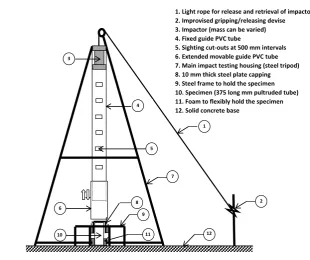
Chapter 4 Investigation on the behaviour of square FRP composite tubes under repeated axial impact Figure Figure caption Page 4.1 Impact testing set-up…..………. 74
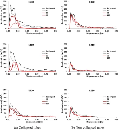
4.2 Typical acceleration-displacement curves in impact testing ……… 80
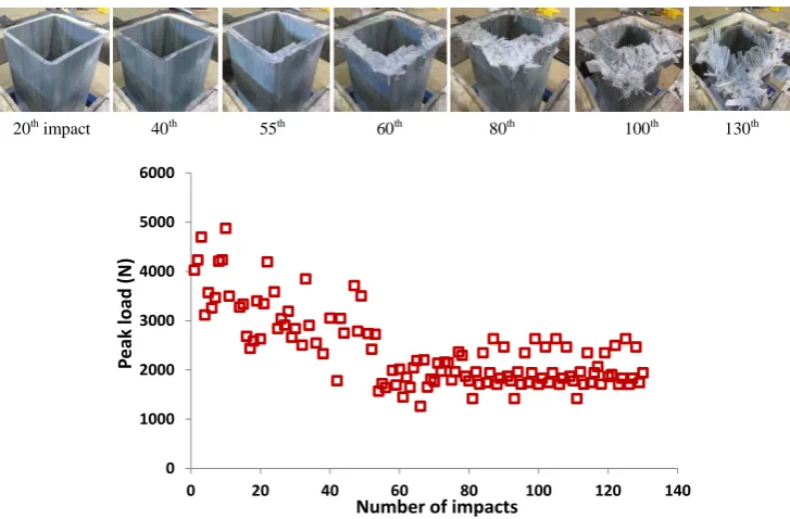
4.3 Condition of the tubes after impact test……….. 81
4.4 Damage progressions of collapsed tube impacted by 476.8 J………. 83
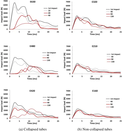
4.5 Impact load histories of repeatedly impacted composite tubes………….. 85
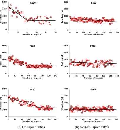
4.6 Peak load progressions of repeatedly impacted tubes……… 87
4.7 Typical energy curves………. 88
4.8 Impact energy histories of repeatedly impacted composite tubes……….. 90
4.9 Comparison of the damage degree curves of repeatedly impacted tubes… 91 4.10 Incident energy vs. Nfcurve of repeatedly impacted tubes………. 94
4.11 Nfvs. drop mass curve of repeatedly impacted tubes………. 95
4.12 Nf vs. impact velocity curve of repeatedly impacted tubes……… 96
Chapter 5 Residual properties of square FRP composite tubes subjected to repeated axial impact Figure Figure caption Page 5.1 Conditions of the tubes after impact test ……… 101
5.2 Cutting plan of coupons used in residual properties testing…...…………. 102
5.3 Compressive test specimens……… 103
5.4 Tensile test specimens ……… 104
5.5 Flexural test specimens ……….. 105
5.6 Scanned images showing typical micro-cracks on the surface of the tubes 106 5.7 Residual strength and impact energy relationships ………109
5.8 Enlarged view: Residual compressive strength-impact energy relationships………... 109
5.9 Enlarged view: Residual tensile strength-impact energy relationships….. 110
5.10 Enlarged view: Residual flexural strength-impact energy relationships… 110 5.11 Residual modulus-impact energy relationships …………... 111
5.12 Enlarged view: Residual compressive modulus- impact energy relationships... 111
5.13 Enlarged view: Residual tensile modulus- impact energy relationships … 111 5.14 Enlarged view: Residual flexural modulus-impact energy relationships… 112 5.15 Residual strength-number of impacts relationships ……... 113
5.16 Enlarged view: Residual compressive strength-number of impacts relationships … ………... 113
5.17 Enlarged view: Residual tensile strength-number of impacts relationships 114 5.18 Enlarged view: Residual flexural strength-number of impacts relationships……….……… 114
5.19 Residual modulus-number of impacts relationship ……... 115
5.21 Enlarged view: Residual tensile modulus-number of impacts
relationships……… 115
5.22 Enlarged view: Residual flexural modulus-number of impacts
relationships ……... 116
5.23 Residual strength-drop mass relationships at different energy levels
and number of impacts……… 117
5.24 Enlarged view: Residual compressive strength-drop mass relationships
at different energy levels and number of impacts……… 117
5.25 Enlarged view: Residual tensile strength-drop mass relationships
at different energy levels and number of impacts……... 118
5.26 Enlarged view: Residual flexural strength-drop mass relationships
at different energy levels and number of impacts ……... 118
5.27 Residual modulus-drop mass relationships at different energy levels
and number of impacts……… … 119
5.28 Enlarged view: Residual compressive modulus-drop mass relationships
at different energy levels and number of impacts……... 119
5.29 Enlarged view: Residual tensile modulus-drop mass relationships
at different energy levels and number of impacts ……... 119
5.30 Enlarged view: Residual flexural modulus-drop mass relationships
at different energy levels and number of impacts ……... 120
5.31 Comparison of residual compressive, tensile, and flexural strengths……. 121
5.32 Comparison of residual compressive, tensile, and flexural moduli……… 122
5.33 Strength and modulus curves plotted at increasing impact energy levels... 123
5.34 Variation of residual compressive strengths with the height of the tube… 125
Chapter 6 Damage modelling of repeatedly impacted FRP composite tubes
Figure Figure caption Page
6.1 Quasi-static compressive test……….. 132
6.2 Normalised energy and number of impacts relationship……… 133
6.3 D vs. N curve of the representative composite tube………... 134
6.4 Idealised lifetime response curve of the repeatedly impacted tube……… 135
6.5 Typical curve described by Ein = aNf-b………... 136
6.6 Variation of the correlation β of glass/vinyl ester composite tubes ……… 137
6.7 Data points with the fitting line showing β and α relationship……… 138
6.8 Typical load-displacement curves from quasi-static compressive test…… 139
6.9 Schematic diagram used in computing (Ec)Quasi-static ……… 139
6.10 b values using Excel 2010 “Solver” function………. 140
6.11 Comparison between the experimental data and repeated impact curve … 141
6.12 Proposed model vs. experimental data for collapsed tubes ……… 143
6.13 Proposed model vs. experimental data for non-collapsed tubes ……….… 144
6.14 Flow chart in establishing the damage evolution curve ……….…………. 145
6.15 Square and rectangular composite tubes ………...……….…………. 147
6.16 Crushed composite tubes………...……….…………. 148
6.17 Load-displacement curves of S125 specimen ………...….…………. 148
6.18 Load-displacement curves of R75x100 specimen …….…...….…………. 149
6.19 Repeated impact curves of the square and rectangular tubes….…………. 151
6.20 Damage evolution curves of square and rectangular tubes ….…………... 152
Chapter 7 Application of the damage evolution model to other types of composite tubes
Figure Figure caption Page
7.1 Repeated impact curves of glass/vinyl ester tubes……….. 161
7.2 Damage evolution curves of GV-C tube ……… 162
7.4 Damage evolution curves of GV-H tube ……… 162
7.5 Data points with the fitting line showing β and α relationship of glass/polyester tubes ……… ……….. 164
7.6 Repeated impact curves of glass/polyester tubes ……… 167
7.7 Damage evolution curves of GP-C1 tube ………... 168
7.8 Damage evolution curves of GP-C2 tube ………... 168
7.9 Damage evolution curves of GP-C3 tube ………... 169
7.10 Damage evolution curves of GP-S1 tube ………... 169
7.11 Damage evolution curves of GP-S2 tube ………... 169
7.12 Damage evolution curves of GP-S3 tube ………... 179
7.13 Repeated impact curves of glass/epoxy tubes ………... 173
7.14 Damage evolution curves of GE-C1 tube ………... 174
7.15 Damage evolution curves of GE-C2 tube ………... 174
7.16 Damage evolution curves of GE-C3 tube ………... 175
7.17 Damage evolution curves of GE-C4 tube ………... 175
7.18 Damage evolution curves of GE-C5 tube ………... 175
7.19 Damage evolution curves of GE-S1 tube ………... 176
Appendix A Summary of results of the coupon and full scale tests on CT1 and CT2 specimens
Figure Figure caption Page
A.1 Compressive load-displacement relationship of coupon specimens (CT1) A-3
A.2 Compressive load-displacement relationship of coupon specimens (CT2) A-3
A.3 Tensile load-displacement relationship of coupon specimens (CT1)……. A-4
A.4 Tensile load-displacement relationship of coupon specimens (CT2)……. A-5
A.5 Flexural load-midspan deflection relationship
of coupon specimens (CT1)……… A-6
A.6 Flexural load-midspan deflection relationship
of coupon specimens (CT2)……… A-6
A.7 Simplified cross section of the tube………. A-7
A.8 Compressive load-displacement relationship of full scale specimens
(CT1, L=100 mm)……… A-8
A.9 Compressive load-displacement relationship of full scale specimens
(CT1, L=200 mm)……… A-9 A.10 Compressive load-displacement relationship of full scale specimens
(CT2, L=100 mm)……… A-9 A.11 Specimen cross section lay-out ….………. A-10 A.12 Schematic plan of 3-point bending test ………. A-10 A.13 Schematic plan of 4-point bending test ………. A-10 A.14 Flexural stress-displacement relationship (3-point bending test) of CT1… A-11 A.15 Flexural stress-displacement relationship (3-point bending test) of CT2… A-12 A.16 Flexural stress-strain relationship (4-point bending test) of CT1………… A-12
Appendix B Summary of specimen dimension and snapshots of the machine/apparatus used in repeated impact test
Figure Figure caption Page
B.1 Repeated impact testing set-up data logger and fixtures………. B-3
B.2 Condition of the specimen after impact test (Test matrix from Table 4.2). B-4
B.3 Condition of the specimen after impact test (Test matrix from Table 4.3). B-4
Appendix C Variation of impact stress with the height of the tube using finite element (FE) analysis
Figure Figure caption Page
C.1 Schematic view of the impacted tube and the idealised model………….. C-2
C.2 Comparison of aL/2and a1 values at varying impact mass ………….. C-2
C.3 Material modelling of the composite tube……….. C-7
C.4 Lamina lay-up arrangement used in FE model……… C-7
C.5 Factor vs. time table for the impulse period of 0.01 second……… C-9
C.6 Variation of the static load case with the measured acceleration………… C-9
C.7 Factor vs. time table simulating repeated impact loading (E630)……….. C-10
C.8 Factor vs. time table simulating repeated impact loading (E480)……….. C-10
C.9 Factor vs. time table simulating repeated impact loading (E420)……….. C-11
C.10 Factor vs. time table simulating material degradation (E630)……… C-12
C.11 Factor vs. time table simulating material degradation (E480)……… C-12
C.12 Factor vs. time table simulating material degradation (E480)……… C-12 C.13 Comparison of time steps for E630……… C-13
C.14 Variation of peak axial stress in longitudinal direction……….. C-14
C.15 Variation of peak axial stress in transverse direction………. C-16
List of Tables
Chapter 2 Review of composite piles and their driving performance
Table Table caption Page
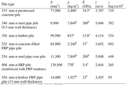
2.1 Comparison of pile impedance……….. 25
2.2 List of applications of hollow FRP pipe piles……… 31
2.3 Mechanical properties of the 125 mm square tube……… 32
2.4 Summary of recent experimental studies on repeated impact test………. 36
Chapter 3 Characterisation of the properties of composite tubes Table Table caption Page 3.1 Section properties of the 100 mm square tube………... 42
3.2 Details of the specimen for fibre fraction test ……… 44
3.3 Summary of glass fibre content of each ply …….……….. 44
3.4 Details of the specimen for coupon tests ……… 45
3.5 Material properties of the tube wall laminate ply ……….. 61
3.6 Summary of mechanical properties from coupon tests ………. 70
3.7 Summary of mechanical properties from full scale tests………. 70
Chapter 4 Investigation on the behaviour of square FRP composite tubes under repeated axial impact Table Table caption Page 4.1 Details of the specimen ……...……… 73
4.2 Test matrix used in defining the impact behaviour………. 78
4.3 Test matrix used in defining the impact damage tolerance……… 78
4.4 Summary of Nfvalues………. 92
Chapter 5 Residual properties of square FRP composite tubes subjected to repeated axial impact Table Table caption Page 5.1 Details of the specimen……… 99
5.2 Repeated impact test matrix……… 100
5.3 Details of the specimen for coupon tests………. 102
5.4 Summary of compression test results………. 107
5.5 Summary of tensile and flexural tests results………. 107
Chapter 6 Damage modelling of repeatedly impacted FRP composite tubes Table Table caption Page 6.1 Details of the specimen used in quasi-static compressive test……… 131
6.2 Summary of (Ec)Quasi-static values……….. 140
6.3 Comparison of incident energies at different Nf………. 142
6.4 Comparison of incident energies at average Nf………... 142
6.5 Properties of S125 and R75x100 specimens ...………... 147
6.6 Summary of parametric values of square and rectangular tubes...……... 149
Chapter 7 Application of the damage evolution model to other types of composite tubes Table Table caption Page 7.1 Details of GV-C, GV-S, and GV-H tubes ……….. 158
7.3 Summary of the repeated impact equation of glass/vinyl ester tubes …... 160
7.4 Details of glass/polyester tubes (circular cross section)…... 163
7.5 Details of glass/polyester tubes (square cross section)…... 163
7.6 Summary of (Ec)Quasi-static and β values of glass/polyester tubes... 165
7.7 Summary of the repeated impact equation of glass/polyester tubes …... 165
7.8 Details of glass/epoxy tubes (circular cross section)………... 170
7.9 Details of glass/epoxy tubes (circular and square cross sections)……... 171
7.10 Summary of (Ec)Quasi-static and β values of glass/epoxy tubes……... 172
7.11 Summary of the repeated impact equation of glass/polyester tubes…... 172
Appendix A Summary of results of the coupon and full scale tests on CT1 and CT2 specimens
Table Table caption Page
A.1 Summary of results of fibre fraction test for CT1……….. A-1
A.2 Summary of results of fibre fraction test for CT2……….. A-1
A.3 Summary of results of coupon compressive test for CT1………... A-2
A.4 Summary of results of coupon compressive test for CT2……… A-2
A.5 Summary of results of coupon tensile test for CT1……… A-4
A.6 Summary of results of coupon tensile test for CT2……… A-4
A.7 Summary of results of coupon flexural test for CT1……….. A-5
A.8 Summary of results of coupon flexural test for CT2……….. A-6
A.9 Summary of results of full scale compressive test for CT1 (L = 100 mm). A-7
A.10 Summary of results of full scale compressive test for CT1 (L = 200 mm). A-8 A.11 Summary of results of full scale compressive test for CT2 (L = 100 mm). A-8 A.12 Summary of results of full scale flexural test (3-point loading) for CT1… A-11
A.13 Summary of results of full scale flexural test (3-point loading) for CT2… A-11
A.14 Summary of results of full scale flexural test (4-point loading) for CT1… A-11
Appendix B Summary of specimen dimension and snapshots of the machine/apparatus used in repeated impact test
Table Table caption Page
B.1 Dimension of specimen E630………. B-1
B.2 Dimension of specimen E480………. B-1
B.3 Dimension of specimen E420………. B-1
B.4 Dimension of specimen E320………. B-2
B.5 Dimension of specimen E210………. B-2
B.6 Dimension of specimen E160………. B-2
B.7 Dimension of specimen E630-1……….. B-2
B.8 Dimension of specimen E480-1……….. B-3
B.9 Dimension of specimen E480-2……….. B-3
B.10 Dimension of specimen E420-1……….. B-3
Appendix C Variation of impact stress with the height of the tube using finite element (FE) analysis
Table Table caption Page
C.1 Material properties of the tube wall laminate ply……… C-7
C.2 Summary of applied static load cases used in FE analysis………. C-10
Appendix D Summary of specimen dimension and results in residual properties testing
Table Table caption Page
D.2 Coupon dimension and compressive test result for E160-80 (Top)……… D-1
D.3 Coupon dimension and compressive test result for E320-80 (Top)……… D-1
D.4 Coupon dimension and compressive test result for E480-10 (Top)……… D-2
D.5 Coupon dimension and compressive test result for E630-10 (Top)……… D-2
D.6 Coupon dimension and compressive test result for E160-80 (Middle)….. D-2
D.7 Coupon dimension and compressive test result for E320-80 (Middle)….. D-2
D.8 Coupon dimension and compressive test result for E480-10 (Middle)….. D-3
D.9 Coupon dimension and compressive test result for E630-10 (Middle)….. D-3
Notations
Roman alphabets
Notation Description
A Cross-sectional area of tube/coupon specimen
a distance between one of the end supports and the nearest applied load,
parametric constant, acceleration
at Acceleration as a function of time or at present time increment
at-1 Acceleration at previous time increment
b Width of the tube/coupon specimen or parametric constant
c Neutral axis depth of the tube or parametric constant
cw Compression wave velocity
D Damage parameter
d Depth of the tube
E Modulus of elasticity
Eabs Absorbed energy
Ec Critical energy (energy causing the failure of tube at one impact)
Ecomp Compressive elastic modulus of tube/coupon specimen
(Ec)Dynamic Critical energy obtained from dynamic (impact) test
Ef Flexural elastic modulus
Eim Impact energy
Ein Incident energy
EK Kinetic energy
EP Potential energy
(Ec) Quasi-static Critical energy obtained from quasi-static compressive test
Esat Saturation energy
Et Tensile elastic modulus
ET Total energy
Ews Energy as a function of displacement
Ewt Energy as a function of time
Fs Load at present displacement increment
Fs-1 Load at previous displacement increment
Ft Impact load as a function of time
g Acceleration due to gravity
h Drop height
h0 Drop height (used in Appendix C)
j Inner depth of the tube
k Inner width of the tube
l Length of the tube /coupon specimen
ls Test span in flexure
L Length of the tube (used in Appendix C)
Mg Fibre glass content in mass percentage
m Mass of the impactor
m0 Initial mass of the specimen used in fibre fraction test
m1 Initial mass of the dry crucible used in fibre fraction test
m2 Initial mass of the dry crucible plus dried specimen used in fibre fraction test
m3 Final mass of the crucible plus residue used in fibre fraction test
mm Equivalent mass at the m
th
point (used in Appendix C)
N Number of impact
Nf Number of impacts to initiate failure/collapse of the tube
Nmax Maximum number of impact
Ppc Peak compressive load of tube/coupon specimen
Ppf Peak flexural load of tube/coupon specimen
Ppt Peak tensile load
(Pm)
0
Maximum load at the 1st impact
(Pm)
N
Maximum load at the Nth impact
I Moment of inertia
Ix Moment of inertia along the x-axis
Iy Moment of inertia along the y-axis
t Thickness of the coupon specimen
R(Nf) Reliability of Nf
ri Internal radius of the chamfered corner of the rectangular tube
re External radius of the chamfered corner of the rectangular tube
sm Travelled distance by the wave at the m
th
point (used in Appendix C)
st Displacement as a function of time
t Present time increment
t–1 Previous time increment
v Impact velocity
vff Volume of the specimen used in fibre fraction test
vm Wave velocity at the m
th
point (used in Appendix C)
v0 Initial velocity of the impactor before hitting the target
vt Velocity as a function of time or at present time increment
vt-1 Velocity at previous time increment
z Pile impedance
Greek letters
Notation Description
α Ratio of the loading rates between quasi-static compressive and impact tests
β Correlation factor
εpc Peak compressive strain of tube or coupon specimen
ρ Mass density/specific mass
ρt Mass density of the tube (used in Appendix C)
σpc Peak compressive stress of tube or coupon specimen
σpf Peak compressive stress
σpt Peak tensile stress
σ1 stress measured at the strain values ε1 = 0.0005
σ2 stress measured at the strain values ε2 = 0.0025
Chapter 1
Introduction
1.1 General
This thesis presents the results conducted to investigate the behaviour of fibre
reinforced polymer (FRP) composite tubes under repeated axial impact loading. The
effects of impact event (incident energy and number of impact) on the instantaneous
response and the residual properties of composite tubes were examined. The
mechanical properties of the tubes used in investigating the impact behaviour of the
tubes and their residual properties were obtained experimentally and using finite
element (FE) analysis. Theoretical prediction using the basic energy principle was
performed to gain additional understanding on the damage evolution behaviour of
composite tubes subjected by repeated axial impact. The damage evolution model
was verified through experimental investigation on a 100 mm square pultruded tube.
The model was applied to composite tubes of different cross sections and materials
made from vinyl ester/polyester/epoxy matrix reinforced with glass fibres. An
improved understanding of the behaviour of glass fibre FRP composite tubes under
repeated axial impact is expected from this study.
1.2 Background
Pile foundations are generally used to support structural loads in situations where soil
settlement is a major concern or where shallow foundations cannot provide the
required bearing capacity (Sakr et al., 2004). Piling industry has historically involved
the use of traditional materials such as concrete, steel and timber as pile foundations.
However, there are problems associated with their use especially when installed in
corrosive and marine environments. These include concrete degradation, steel
corrosion, and marine borer attack or deterioration of timber piles. Examples of
deteriorated traditional piles in harsh environments are shown in Figure 1.1.
The deterioration of concrete, steel and timber reduces their structural
capacities, which may ultimately result in damage or failure of the structure
of deteriorated piles, and with disruption to the public’s use of facility, can be very
high and in certain circumstances often exceed the original of the construction cost
(Neff, 2003). Lampo et al. (1997) estimated that the deterioration of concrete, steel
and timber piles costs the U.S. military and civilian marine and waterfront
communities nearly $2 billion a year. Aside from the cost, there is a growing concern
in the environmental and health impact of using treated pile materials. Creosote and
Copper Chromium Arsenic (CCA) treated timber pose a threat to marine life and the
workers who handled during manufacturing and installation are in potential health
risk (Iskander et al., 1998). Similarly, steel treated using sandblasting or painted with
solvent and heavy-metal containing coatings are potentially harmful to the
environment and are increasingly being regulated (Lampo et al., 2007).
Conclusively, using same material in the rehabilitation and replacement of these
deteriorated traditional piles is not an optimum solution as apparently the cycle of
inherent problems of their usage will just be repeated. These problems coupled on
the use of traditional piles led researchers around the world to look for viable
alternative materials that are suitable in harsh environments.
(a) Degraded concrete pile (b) Corroded steel piles (www.substructure.com) (www.watimas.com)
(c) Deteriorated timber piles (www.majorprojects.vic.gov.au)
1.3 Fibre composites as an alternative in piling applications
In the last 200 years, rapid advances in construction materials technology have
enabled civil engineers to achieve impressive gains in safety, economy, and
functionality of structures built to serve the common needs of the society (Bakis et
al., 2002). These include the consideration and application of fibre reinforced
polymer (FRP) composite materials in civil engineering. Their application is of most
importance in the renewal of constructed facilities infrastructure such as buildings,
bridges, pipelines, etc. Their use has also increased in the rehabilitation of concrete
structures, mainly due to their tailorable performance characteristics, ease of
application, and low cycle costs (Einde et al., 2003).
The application of FRP composite materials in piling system is relatively new
compared to other civil engineering applications. The application of “composite
piles” was first recorded in the late 1980’s (Iskander and Hassan, 2002). Composite
piles refer to alternative pile foundations composed of fibre reinforced polymers
(FRP), recycled plastics or hybrid materials that are placed into the ground to support
axial and/or lateral loads (Pando et al., 2006). They are considered viable alternatives
due to their inherent advantages over traditional piles. Their advantages include light
weight, high specific strength, high durability, corrosion resistance, chemical and
environmental resistance, and low maintenance cost (Sakr et al., 2005).
On the other hand, there are also potential drawbacks of using composite
piles. Iskander and Hassan (1998) enumerated four disadvantages of using composite
piles. First, their initial cost is generally expensive compared to traditional pile
materials. This disadvantage, however, is relative, as the overall cost is expected to
decrease as composite piles gain wider penetration in the civil engineering industry.
Ballinger (1994) emphasised that, although the cost of FRP composite materials may
be higher, the cost of labour and use of equipment necessary for construction work
may be lower due to their lighter weight. Pando et al. (2006) suggested that not only
should costs be compared on a total installed first-cost basis but also on a reasonable
total life cycle cost basis. Most composite piling manufacturers believe their products
may be competitive when compared to the life cycle cost of traditional piles in some
applications (Ballinger, 1994). For instance, Iskander and Hassan (1998) reported
that manufacturers claim their composite piles may last twice as long as treated
wooden piles. The second drawback of using composite piles is due to their inherent
the settlement permitted by the codes. Moreover, their low modulus (or stiffness)
property may cause problems during installation and handling. In some situations,
however, their low modulus property provides an added advantage of their use.
Traditional piles are considered too stiff for fendering application, thus, making
composite piles an ideal potential use. They can also dampen seismic forces
transferred to the structure through the foundation and they may reduce moments in
piled rafts (Iskander and Hassan, 1998). The third drawback of using composite piles
is that their long-term performance under increasingly larger structural loads is not
yet well defined. An attempt has already been performed by Pando et al. (2006) to
monitor the long-term performance of two composite piles located in Route 351
Bridge in Virginia, U.S.A. The fourth disadvantage of their use is that composite
piles are generally less efficient to drive than traditional piles. Their poor driving
performance was attributed by their inherent low impedance property (Mirmiran et
al., 2002; Ashford and Jakrapiyanun, 2001). Impedance is associated to the ability of
the pile to transmit the energy imparted by the driving hammer into the ground
(Pando et al., 2006). The detailed discussion on the impedance properties of
composite piles is presented in Chapter 2. Although composite materials present a
number of disadvantages related to their application in piling system, the use of
composite piles is still an alternative that will eliminate deterioration problems of
traditional piling materials in waterfront environments and aggressive soils (Iskander
et al., 2001).
1.4 FRP tubes as composite piles
Composite piles have been used in ports and harbours primarily as waterfront
barriers, fender, and bearing piles for light structures (Iskander and Hassan, 1998).
Among composite piles; structurally reinforced plastic (SRP) pile, steel pipe core
pile, concrete-filled FRP pipe pile; and hollow FRP pipe pile are generally
considered to be potentially suitable in load-bearing applications. Previous studies
conducted on the first three types of composite piles, however, showed some
concerns of their use in this application. Common problems of these piles are
debonding between the component materials (Mirmiran et al., 2000; Pando et al.,
2006) although techniques are being developed to minimise its occurrence (Baxter et
al., 2005; Fam and Rizkalla, 2002). Steel pipe core piles have some integrity issue
1998). On the other hand, SRP piles have issues on handling and installation
(Iskander et al., 1998) and structural performance due to its inherent excessive
deformation behaviour. As a result, the last type of composite piles is considered a
comparably good option in piling application and is the focus of the present study.
The emergence of FRP composite tubes as a structural component provided
the industry to consider these materials as a potential composite load-bearing pile
type since they can carry design load. For instance, square-shape composite tubes
bonded to an FRP plate are used as a structural decking in a flooring system (Bakis et
al., 2002). In Australia, pultruded composite tubes were used as fibre composite
bridge decking unit, as transmission line cross arms, and as a major structural
component of a fibre composite bridge girder (QDMR, 2006). Compared to
concrete-filled FRP pipe pile, hollow FRP pipe pile can be readily installed without the
intricacy of placing concrete infill using additional equipment. The cost of
transportation and installation is also lower due to their lighter weight, thus more cost
efficient. Additionally, bond failure (i.e., delamination between FRP shell and
concrete core in the case of concrete-filled FRP pipe pile) is not an impending issue
on the use of this pile.
1.5 Challenges in using hollow FRP pipe piles
One of the main challenges in the efficient use of composite piles is to ensure that
they can carry the intended design loads and be installed to the necessary depth. This
challenge is attributed to the techniques on how they are being placed into the
ground. Like other types of composite piles, hollow FRP pipe piles are commonly
installed using impact driving. This method drives a pile by raising a weight between
guideposts and dropping it on the head of the pile. In this installation technique,
hollow FRP pipe piles were found to exhibit poor driving performance due to their
low impedance. Field test results showed that their thin-walled section generally
shatters under high driving stresses when encountering sand layer or boulders
(Mirmiran et al., 2002). Due to this rupture, their integrity and post-impact
performance is in question.
The impedance characteristics of hollow FRP pipe piles are inherently
material-dependent and therefore increasing it may not be simple. For instance, the
cross-sectional area of the hollow FRP pile can be increased; doubling the wall
materials are the primary cost in the manufacture of hollow FRP piles (Ashford and
Jakrapiyanun, 2001), doubling the wall thickness could also nearly double the cost.
The compression wave velocity of the hollow FRP piles is directly related to their
modulus of elasticity (Iskander et al., 2001). The elastic modulus can be varied by
the fibre orientation. However, analytical study showed that varying the fibre
orientation still not sufficient to increase significantly the modulus leading to the
increase of impedance (Ashford and Jakrapiyanun, 2001). On the other hand, the
effect of the specific mass on the impedance of hollow FRP pile is not
straightforward. Aside from the fact that it is difficult to increase due to their inherent
lightweight characteristics, increasing it would results to only minimal contribution
as this parameter will also reduce the wave velocity.
Increasing the impedance by working on the material parameters such as
specific mass, elasticity and area is not an optimum solution to enhance the driving
performance of hollow FRP piles. Working on some aspects such as driving
installations may also found to improve their driving performance. Few
recommended installation techniques include using steel mandrel to essentially drag
the pile into place or to use high-frequency vibratory driver (Mirmiran et al., 2002;
Ashford and Jakrapiyanun, 2001). So far, the feasibility of adopting these alternative
driving techniques to hollow FRP piles has not been implemented yet in actual field
condition. Recently, Sakr et al. (2004) developed a driving technique called toe
driving to install the hollow FRP piles into granular soils. This driving method was
carried in a laboratory where the large-scale model hollow FRP pile was driven in
dense dry sand enclosed in a pressure chamber. Since the result is based on
experimental investigation in a laboratory facility, there is still a need to confirm this
method using field tests in various subsurface conditions.
1.6 Research needs related to their driving performance
Hollow FRP pipe piles have poor driving performance due to their inherent low
impedance. Similarly, driving them requires more careful consideration due to their
relatively low stiffness and thin walls. The fibre composite materials of the hollow
FRP pipe piles are susceptible to impact damage using the current installation
method. Characterisation of the impact damage behaviour of fibre composite
materials is highly important as they exhibit distinctive damage characteristics
might be no damage indication on the surfaces by visual evaluation but internal
damage may have occurred (Zhang and Richardson, 2007). This damage may have
an adverse effect on the structural integrity and post-impact performance of the
composite materials.
Previous studies related to the driving performance of hollow FRP piles only
include superficial consideration of the impact behaviour of the fibre composite
materials and does not systematically describe their impact strength. These studies
described the impact behaviour of the fibre composite materials through the observed
damage mechanisms only. Moreover, the effects of the damage parameters such as
impact energies and number of impacts on the behaviour of fibre composite materials
have not been fully investigated. The effects of these parameters should be clearly
understood to determine whether by varying their magnitude results in significant
changes on their impact strength and damage behaviour. Consequently, issues related
to the determination and prevention of impact induced damage on fibre composite
materials become more important, and there is a need to develop an understanding of
damage phenomena at the materials level. Literature revealed that the studies on the
behaviour of FRP composite materials subject to repeated impact are limited only to
composite laminates/panels or tubes under transverse impact. Therefore, a need to
conduct a study on the behaviour of composite tubes under repeated axial impact is
of prime priority.
1.7 Objectives
The evaluation of the impact behaviour of fibre composite materials is significant to
describe their driving and post-impact performance. The aim of this study is to
investigate the behaviour of glass fibre reinforced polymer (GFRP) composite tubes
under repeated axial impact. The main objectives of the study are the following:
(a) Characterise the effects of energy, impact mass, drop height/velocity, and
impact repetitions on the impact behaviour of square GFRP composite tubes
experimentally;
(b) Investigate the residual (after-impact) properties behaviour of repeatedly
impacted square GFRP composite tubes;
(c) Develop prediction model on the impact damage evolution of square GFRP
(d) Investigate the potential application of the proposed damage model to other
GFRP composite tubes with different properties (i.e., geometry, matrix
material).
1.8 Scope of the thesis
The study focused on understanding the behaviour of GFRP composite tubes subject
to repeated impact for piling application. The composite tubes used in this study are
commercially manufactured using pultrusion process. Due to commercial sensitivity,
further information on the details of fibre and matrix cannot be revealed. Similarly,
the manufacturing process of these pultruded tubes are not publicised, however, a
general idea on pultrusion process referenced from the literature is presented. The
following are considered during the progress of the study.
Review on the driving performance of composite piles and recent development on hollow FRP pipe piles, and impact studies on FRP composite
materials;
Characterisation of the material properties of square GFRP composite tubes; Testing and evaluation of the behaviour and failure mechanisms of square
GFRP composite tubes under repeated axial impact;
Testing and evaluation of the residual properties behaviour of the repeatedly impacted square GFRP composite tubes;
Development of an energy-based model predicting the impact damage behaviour of square GFRP composite tubes;
Comparison of the results from experiment and proposed damage model; Investigation of the energy absorption behaviour of other FRP composite tube
materials (from quasi-static compressive tests and directly from the
literature); and
Application of the proposed model to these FRP composite tubes.
On the other hand, the following are beyond the scope of this study and
considered potential areas of research in the near future:
Evaluation of the behaviour of GFRP composite tubes under actual pile driving considering the effect of soil;
1.9 Outline of the thesis
This thesis contains 8 chapters in which each describes the different investigations
conducted in this study.
Chapter 1 gives an introduction and objectives of this study. This chapter highlights the existing problems and the motivation of conducting an impact
study on FRP composite materials. This also discussed the significance of the
study relative to the use of FRP composite tubes in piling application.
Chapter 2 provides an overview on composite pile technologies and their behaviour under impact driving. As this work emphasised the use of hollow
FRP pipe piles in load-bearing applications, the recent development of their
applications is also presented. The studies worldwide on the impact behaviour
of FRP materials as a research need related to their driving performance are
highlighted.
Chapter 3 presents the characterisation of the mechanical properties of square GFRP composite tubes used in this study. The manufacture of composite
tubes using pultrusion process is discussed. A finite element (FE) analysis
on the compressive and flexural behaviours of full scale specimens was
also included in the discussion.
Chapter 4 characterises the behaviour of the square GFRP composite tubes through experimental investigation. The effects of impact energy, drop mass,
drop height/velocity, and the number of impacts are highlighted in this
chapter.
Chapter 5 emphasises on the characterisation of the residual properties of the square FRP tubes under repeated axial impact. In this study, the residual
properties of composite tubes were characterised by determining the residual
properties of the coupons cut from the impacted tube for each impact
condition.
Chapter 6 covers the development of a predictive model to characterise the damage evolution of a repeatedly impacted square GFRP composite tubes.
This model adopts an energy-based approach in simulating the damage
evolution curve.
square, rectangular, and circular sections, tubes with bigger dimension, and
tubes with matrix material made of polyester and epoxy.
Chapter 8 presents the main conclusions of the research and recommendations for future work.
1.10 Summary
Hollow FRP pipe piles have been a viable option in replacing traditional pile
materials such as concrete, steel and timber in harsh environmental conditions.
Driving these piles, however, requires more careful consideration due to their
relatively low stiffness and thin walls. The possibility of damaging the fibre
composite materials during the process of impact driving is always a concern.
One of the main factors that affect the driving performance of these piles and
needs special attention is the impact strength of the fibre composite materials.
Therefore, there is a need to understand the impact behaviour of these materials
in order for them to be safely and effectively driven into the ground. This