Thesis by Sankaran Srinivas
In Partial Fulfillment of the Requirements for the Degree of
Doctor of Philosophy
California Institute of Technology Pasadena, California
1977
DEDICATION
I would like to thank: Prof. G.D.Mccann
Dr. M.Weinstein
Dr. W .M.Whi tney and Mr. L.Friedman
Dr. G.Ingargiola, Prof. F.B.'lllompson
ACKNCWLEDGEMENI'S
for his help and support during my years at Caltech,
vtio got me started in this area of research, pointed out the importance of the problem of error recovery, suggested many ideas, and
helpful guidance and encouragement ,
provided
for helping me formulate discussions .arrl for
my ideas providi03 encouragement at needed moments,
through many the right
for their important role in teaching me many important concepts of computer and information and Prof. P.B.Hansen science,
Prof. R.H.Cannon
Shr iram Udupa
and Scott Roth
Lorraine Alvarez
Caltech and JPL
for making some useful suggestions regarding the
presentation of the general contributions of this
thesis,
my fellow students, for many interesting,
speculative, and
making my stay
enjoyable,
valuable discussions, and for
at Caltech both memorable and
without whose help, support, encouragement, and
confidence in my abilities, this thesis YX)Uld
never have been completed,
for providing-me with financial assistance in the
form of tuition scholarships, graduate teaching
assistantships, and graduate research
ABSTRACT
This dissertation addresses itself to the problem faced by a robot in recovering from failures during execution of a task. Failures occur partly because sensory information is inaccurate, partly because effectors do not always perform as expected, and partly because the domain in which the robot operates cannot be characterized exactly. Robot systems with automated planners have traditionally dealt with the problem of error recovery by merely replanning to achieve the desired goal, without attempting to characterize the failure in any way whatsoever.
The central idea in this thesis is that planning recovery from failures has its own special techniques, distinct from those used in conventional planning systems. 'IWo viewpoints, looking at the past for an explanation of the failure, and looking at the current situation to attempt a characterization of the failure state, provide powerful heuristics for error recovery. This thesis suggests that these heuristics can be formalized as failure reason analysis and multiple outcome analysis, ·and that knowledge relevant for such analysis can be provided through a failure reason model and a multiple outcome model associated with each action.
'Il1e
knowledge
failure reason model about why actions
required for distinguishing between the different reasons for failure.
Finally, it includes recorrunendations of corrective actions to be taken
if failure is attributed to a specific reason. This model in used in
failure reason analysis in building a failure tree representing possible
explanations of the failure. The explanations represented in the tree
are then used in planning recovery.'
The multiple outcome model provides a way of representing the
possible outcanes of an action, like bumping onto the object or bumping
onto the ground in the immediate vicinity of the object, ignoring the
fact that these outcomes could be the result of several different
reasons. Knowledge required to distinguish between different outcomes
is provided as part of the model. In cases where the immediately
available information is inadequate to identify the outcome of an
action, the multiple outcome model provides a basis for executing
actions to serve as information gathering steps. 'llle novel feature here
is that information gathering is directed by specific expectations about
the state of the world.
A computer implementation of a program called MEND has providea a
medium for exploring the above idea. MEND has been designed to automate
recovery from failures in simple manipulation tasks to be performed by
the JPL robot, but the techniques used in MEND have greater generality.
A first implementation of MEND established the basis of this
investigation. A second version, which has been designed to correct
some limitations of the first version, has not yet been fully
The techniques of planning recovery from failures through failure
reason analysis and multiple outcome analysis are contributions to the
subject of robotics. r-bre imp:>rtantly, however, the problem of error
recovery is recognized to be a member of a larger class of problems
involving knowledge representation and common sense reasoning, both of
which are core topics in the study of artificial intelligence. '!he
solution presented in this thesis makes some new contributions to these
TABLE OF CONTENTS
1 INTRODUCTION
1.1 Problem Description
1.2 An overview of MEND
1.3 Other approaches to the problem
1.4 An overview of the report
2 THE JPL ROBor
2.1 Introduction
2.2 JPL program objectives
2.3 JPL robot hardware
2.4 Tasks and goals
2.5 System components and structural organization
2.6 Example of execution
2.7 Errors and a module for error recovery
3 A DESCRIPTION OF MEND
3.1 Introduction
3.2 The internal structure of MEND
3.3 World model
3.4 Knowledge about actions
3.5 The execution trace
4 FAILURE REASON ANALYSIS 50
4.1 Introduction 50
4.2 A classification of failure reasons 50
4. 3 The failure tree 53
4.4 Building a failure tree 55
4.5 The failure reason model 58
4.6 Scenarios 66
4.7 Corrunents and com}?arisons 77
5 MUL'rIPLE OUTCCME ANALYSIS 81
5.1 Introduction 81
5. 2 An example : MOVE-HAND-'1'0-GRASP 8 2
5.3 A second example : GRASP 92
5.4 Failure reason analysis versus multiple outcome analysis 94
5.5 Integration of the two schemes 95
6 SUMMARY AND CON:LUSIONS 97
6.1 Introduction 97
6. 2 Historical note 97
6.3 A discussion of the approach 98
6.4 Features of the solution 100
6.5 Contributions 103
7 REFERENCES 107
8 APPENDIX-1 112
INTRODUC'rION
1.1 PROBLEM DESCRIPI'ION
A robot performs a task by executing a plan of actions. During
execution the robot may encounter a variety of unforeseen circumstances,
some of which prevent successful completion of the task. Even simple
actions such as reaching out to grasp a rock cannot be guaranteed to
succeed in the absence of dynamic sensory feedback as in visual
monitoring of manipulation tasks. The hand may bump onto the rock
because of manipulation errors or because of erroneous information about
the location of the rock. Failures such as these occur because sensors
and effectors are inaccurate, and because the world in which the robot
operates cannot be characterized exactly.
0..lr goal is to design a robot in such a way that it can recover
from failures in a graceful and intelligent manner. Robot systens with
automated planners have traditionally dealt with the problem of error
recovery by merely replanning to achieve the desired goal, without
attempting to characterize the failure in any way whatsoever.
The central idea in this thesis is that planning recovery from
failures has its own special techniques, distinct from those used in
conventional planning systems. The techniques of recovery planning are
based on knowledge about failures -- why they occur, what can be done
about them, etc. '!Wo viewpoints, looking at the past for an explanation
characterization of the failure state, provide powerful heuristics for
error recovery.
A computer implementation of a program called MEND has provided a
medium for exploring the above idea. MEND has been designed to automate
recovery from failures in simple manipulation tasks to be performed by
the JPL robot, but the techniques used in MEND have greater generality.
A first version of MEND established the basis of the investigation
reported here. A second version, which has been designed to correct
some limitations of the first version, has not yet been
implemented and integrated with the JPL robot system.
1. 2 AN OVERVIEW OF MEND
-FJGURE LI
NON
Ri:AL TIME
(PLANNING)
COMPUTER
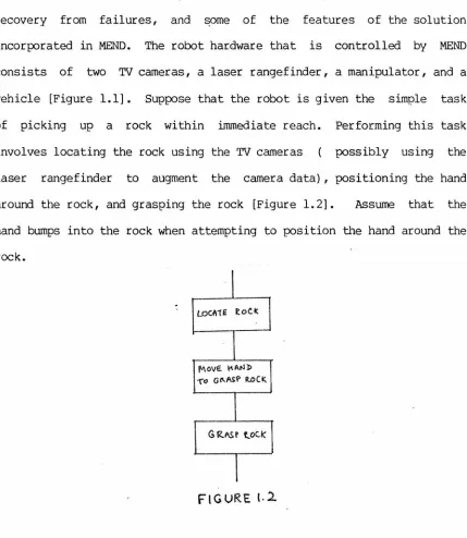
Let us consider an example to illustrate the problems involved in
recovery from failures, and some of the features of the solution
incorporated in MEND. The robot hardware that is controlled by MEND
consists of two TV cameras, a laser rangefinder, a manipulator, and a
vehicle [Figure 1.1]. Suppose that the robot is given the simple task
of picking up a rock within irrunediate reach. Performing this task
involves locating the rock using the
rrv
cameras possibly using thelaser rangefinder to augment the camera data) , positioning the hand
around the rock, and grasping the rock [Figure 1.2]. Assume that the
hand bumps into the rock when attempting to position the hand around the
rock.
l'v\OVE. I'\ AtJI> '{"o Gl\.ASP R.OCI::.
FIGURE t.2
Any robot system designed to recover from failures must be able to
detect them. In the above example, the manipulator system triggers the
failure, bringing MEND into action. In other cases, MEND has to make
explicit checks of certain conditions to detect whether or not something
[image:13.612.102.531.103.597.2]that only those conditions that are easy to check on the basis of the available information are tested. A consequence of this lack of comprehensiveness is that failures can propagate down the plan and may be detected only at a subsequent step. This places an additional burden on the recovery scheme. At this point we merely note the intimate relationship between execution monitoring and error recovery.
Having detected a failure, MEND is confronted with the problem of dealing with the unexr;iected event. Two general heuristics provide guidelines to planning recovery.
1.2.1 Failure reason analysis
The first heuristic suggests that recovery actions can be found by determining why the failure occurred. The process of finding an explanation for the failure is termed failure reason analysis. Knowledge necessary for failure reason analysis is provided through a failure reason model associated with each action. The failure reason model represents knowledge about the different reasons for failure of an action, the way in which they may be distinguished, and finally about what can be done to recover from a si;:>ecific kind of failure.
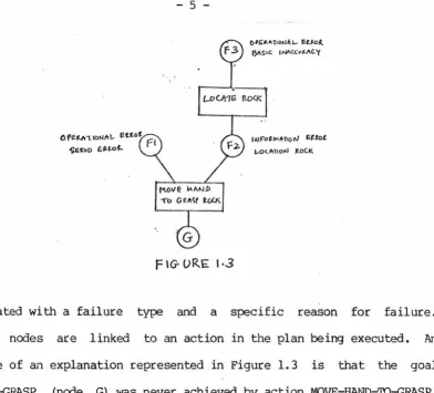
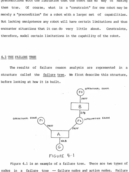
MEND represents possible explanations for a failure in a structure called the failure tree, an example of which is shown in Figure 1. 3. 'Ihe tree consists of a linked set of failure nodes and action nodes. There are four basic types of failure reasons that are dealt with in
MEND and they are information errors,
precondition er~, and constraint errors.
f'\OVE ~/\t-1.l> 1'"o Gil\tf ~
F \G-URE I ·3
t>IG'."-"TION/..1- l'-t.W(
(YIStC IN'>CCvµ\C "(
1AJF"o~"'l\l10 ~ f.t'°t.
1-0U'cTION 1.0C.I<.
associated with a failure type and a specific reason for failure. Action nodes are linked to an action in the plan being executed. An example of an explanation represented in Figure 1.3 is that the goal WITHIN-GRASP (node G) was never achieved by action MOVE-HAND-'.IQ-GRASP, tiecause of an Op:!rational SERVO-ERROR (node Fl) .
[image:15.613.136.528.56.411.2]+
flGV~E
Ffllt.UU: T~IGG-Elt~D ~'I !)vMP o('lTo Rc>CK
Once an explanation has been found, recommendations of corrective
steps can lead MEND to successfully planning recovery from failures.
For instance, if the failure is attributed to SERVO-ERROR [Figure 1.3],
then recovery can be simply achieved by repositioning of the hand as
shown in Figure 1.5.
1.2.2 Multiple outcome analysis
The second heuristic ignores the reason for failure and suggests
that recovery strategies can be found by determining what the outcome of
an action is. This characterization is formalized as multiple outcome
analysis and is directed by a multiple outcome model.
L
LEFT-TOVCH f\\G-Hr-ToUCJ-1
Continuing with our example, MEND finds from the multiple outcome
model that some of the p:>ssible outcanes of f(>sitioning the hand around
the rock are as shown in Figure 1.6. Either the fingers could have
bumped onto the object, or the hand could have bumped onto the ground
because of overshoot. 'Ihe outcomes could be the result of servoing
errors, object location errors, or a combination of these, but this is
unimportant for multiple outcome analysis. MEND attempts to find the
actual outcane of an action when failure has occurred by running a
series of tests. These tests are based on the fact that each outcome is
characterized by a set of conditions that must be true or false for that
situation. To illustrate an example of such a set of conditions is
conditions can be checked on the basis of immediately available
information.
L!;;F'T TOOC..f.( SE~o~ oN
~IG+rr IOl)CK Si:NSoft.. CANNOT Sf AC.TIVA-TED
L HAN!> ON OB:fEC:r
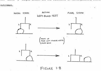
'Ille available information may not always suffice .to identify the
failure state. In such cases the multiple outcome model directs ME.'ND in
the execution of actions to collect the necessary information. Figure
1.8 shows a simple action and its functions in distinguishing between
outcomes.
Ac.:fl"N F1Nt\L STIHE
LEFT-~vMP-i£ST
- - - t >
L
[image:18.612.93.520.401.700.2]Finally, the multiple outcome model includes recorrunendations for recovery strategies for each possible outcome. An example of this is shown in Figure 1.9.
L
<;"EARG{ TO Tfi E Lf.FT
...
l~~
101
1. 3 orHER APPROACHES TO THE PROBLEM
'llle problem of getting robots to do useful things has been tackled in two distinct ways, and each of these approaches has implications for the way in which failures are handled. We shall refer to the two approaches as the higher level language approach and the planning approach. The distinction between the two methodologies becomes blurred in certain systems. Nevertheless it is a useful distinction for our discussion.
could be designed to deal with failures. However, the system itself had
no knowledge about failures Qnd how to deal with them. Continuing
studies at Stanford have led to to the develoµnent of AL [Finkel 74], a
specialized language for automated assembly tasks.
can be dealt with by explicit programming for each
Here again, failures
task. Subroutines
can encapsulate some recovery strategies, but incorporating knowledge
about failures in subroutines has many limitations. For example, it
becomes difficult (or even impossible) for the system to analyze
failures an::] attribute the failure to a previous action that did not
produce the desired result. In MEND such analysis becomes feasible
because of a more explicit representation of knowledge about failures.
Consider now the planning approach. Here tasks are specified as a
goal state to be achieved. An automated planner finds a sequence of
steps to achieve the goal. In systems of this sort, failure during
execution can be dealt with by replanning from the failure state to the
goal state. It would seem that this provides a natural solution to the
problem.
However, there is a basic problem in this whole approach that makes
it difficult to deal with failures in a direct way. If we consider
WITHIN-GRASP(RO::K) to be the desired goal state of positioning the hand
to grasp an object, a failure such as bt.nnping into the rock will be
respon::]ed to by replanning to achieve the goal. It would not be
difficult for the planning system to determine that this can be done by
locating the rock, and then positioning the hand. 'Ibis is fine, but
repositioning of the hand would be adequate if the failure were the
result of servoing errors. To state it in more general terms, modelling
actions merely in terms of preconditions and postconditions is not
adequate in analyzing what caused the failure and what can be done about
it. Such analysis in needed to construct practical recovery strategies.
A number of systems falling within the planning paradigm are
described, in spite of the fact that the above criticism can be levelled
against them. 'Ihey are described because they embody some important
concepts relevant to our discussion.
The planning approach is exemplified by the SHAKEY system [Raphael
71, Fikes 71]. Plans produced by STRIPS, the SHAKEY planner, were
structured into triangle tables. 'Ihe triangle tables gave precise
meaning to the concept of a kernel -- the set of conditions that were
relevant to the execution of the plan. Specifically, the important
property is that the truth of the kernel associated with each action in
a plan ensured that the subsequent steps would succeed (barring
operational failures). Furthermore, this concept allowed SHAKEY to be
clever in replanning from failures by attempting to achieve intermediate
goal states.
Nilsson[73] has dealt briefly with the problem of error recovery in
studying nethods for integrating planning and execution. He identifies
two kinds of events -- failures and surprises -- that a robot must deal
with in a dynamic and uncertain world. His notion of failures includes
execution time failures which we are concerned with, but also
by the simple means of repeating the failed action, but the system had
no good understanding of whether. this would work or not.
The notion of surprises is a consequence of a dynamic world in
which other agents play a role in changing the world. Nilsson suggests
that these probl~ns be tackled by the use of demons set up to watch for
certain conditions. 'lhe demon would transfer control to a higher level
executive when its activating conditions were made true. The hope was
that the higher level executive would be able to deal with the surprise
since it was the one which set up the demon.
Surprises are dealt with in an interesting manner by Hayes[75].
His system uses a representation of robot plans that make explicit the
relationship between decisions and subgoals. New information is dealt
with by discarding portions of the plan which are dependent on the new
information. Replanning fills in the rest in a manner appropriate to
the new situation.
MEND does not specifically deal with the problem of surµrises, and
will remain oblivious to new information about the world as long as it
does not cause an immediate failure. It deals with the situatio~ when
failures occur, but is short-sighted in not checking for future
failures.
Sacerdoti describes a system called NOAH [Sacerdoti 75] which uses
a data structure called a proc~>dural net for planning and execution.
NOAH does not have a good model of why actions fail and therefore
when a failure is detected. Having identified the substep which failed,
NOAH resp:::mds by replanning
to
achieve the intended effects of thisaction.
'llle approach that has been adopted in MEND is closest in spirit to
that taken by Sussman and Goldstein. Sussman's system, HACKER [Sussman
73], is designed to learn to build structures in the BLOCKS world, and
Goldstein deals with the problem of debugging incorrect "line drawing"
programs through a system called MYCROFT [Goldstein 74]. 'Ihe main
difference is that their systems are addressed to the problem of
handling conceptual errors. 'lhese conceptual errors arise either as a
result of a lack of knowledge about the domain or because of an
erroneous first attempt at planning, where interactions between related
steps are not considered. In spite of this basic difference, ~1e can
make a i;x>int of comparison with HACKER. HACKER's analysis of failure
reasons is based on an explicit representation of the previous states of
the world in different contexts and an implicit representation of
previous actions in the control frarries created by calls on the action
routines. Such mechanisms are quite impractical. In analyzing
failures, MEND does not have access to the previous states of the world,
and can only use currently available information and a record of actions
1. 4 AN OVERVIEW OF THE REPORI'
The following two chapters describe the hardware and software of
the JPL robot, the structure of MEND, the world model, the
interpretation of actions, and the detection of failures. Chapter 4
describes the process of failure reason analysis and how it is used in
recovery from failures. A number of scenarios illustrate MEND's
capabilities. Chapter 5 presents a brief outline of multiple outcome
analysis and discusses the problem of integrating failure reason
analysis and rnul tiple outcome analysis. The final chapter swrunar izes
the results, discusses the limitations of MEND, and .suggests ~ssible
THE JPL ROBor
-2.1 INTRODUCTION
The problem of error recovery discussed in the previous chapter was
studied as part of the Jet Propulsion Laboratory's research program in
robotics. In fact the results reported in this thesis are · abstractions
of the design concepts implemented in a module called MEND which is one
of the components of the robot software system. Tnis thesis gained
substance from some of the actual problems encounter~ in the JPL robot
system, and these problems placed realistic requirements on the program
designed for error recovery.
'Ihis chapter gives an overview of the JPL robotics program,
describing its motivation, hardware, tasks and goals for the robot, the
components of the system, and their structural relationships.
2.2 JPL PR(X;RAM OBJECTIVES
Robots, autonomous or semi-autonomous · machines with human like
capability, are considered essential for planetary exploration.
Machines that perform tasks on a step by step basis under human control
are very inefficient when there is significant time delay in
conununication between the hwnan control center and the machine.
Difficulties are further exaggerated because of limitations in channel
largely unknown, or at least unpredictable in detail, manipulation and locomotion will have to be achieved by execution of a large number of highly conservative steps. It is only by such means that environmental hazards can be avoided with reasonable chance of success. The above considerations motivate the JPL robotics research program. 'Ihe long range goals of the project are to demonstrate the usefulness of artificial intelligence concepts for integrated robot systems, and arrive at guidelines for their design. More specifically, the irrmediate goals of the program are to build a breadboard robot system. This will be described next.
2. 3 JPL ROBOT HARO'JARE
'Ihe hardware of the breadboard robot system is shown in Figure 1.1. The manipulator, TV cameras and the laser rangefinder are mounted on a four wheeled vehicle. 'Ihe hardware thus provides for three essential functional capabilities -- manipulation, vision and locomotion.
2.3.1 ARM hardware
y
6 JOINT 11_6
FtGUR£ 2
.
1
the manipulator. A detailed study of the work space of the JPL
manipulator has been performed by Bejczy[72]. The manipulator can lift
objects of about five pounds, and fast system response makes it possible
for most trajectories to be executed within five seconds.
'Ihe manipulator is driven by permanent magnet torque motors.
Electro-mechanical brakes hold the manipulator in position without the
need for driving the motors. Feedback information is made available
from each joint by means of potentiometers for T?Osition information, and
tachometers for rate inforrr0tion. 'Ihese are used by the servo loops
implementing the real time control of the manipulator. Subsequent
chapters will show the importance of position feedback information for
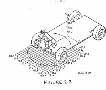
SCAii IN cm
Fl GU RE 2. 2
Figure 2.2 shows the reference frame which is used for manipulation purposes. 'Ibis reference frame will be called the robot coordinate system. The actual position of the hand will be referred to as the position in robot coordinates. 'Ihe position of the manipulator can be
[image:28.612.107.479.60.376.2]2.3.2 EYE hardware
The combination of the TV camera and the laser rangefinder system
will be collectively referred to as the vision system [Williams 76].
Both are mounted on a pan and tilt mechanism and provide the primary
means of sensing the environment.
'IWo solid state (charge-injection device) TV cameras provide stereo
image data to the robot. The image array has 244 lines with 188
elements per line. '!he laser rangefinder is built around a gallit.nn
arsenide pulsed laser. The resolution in the workspace of the robot is
about a quarter inch in the horizontal direction and a half inch ~n the
vertical direction.
As with the manipulator, there is ·a position error that is to be
contended with in the vision system. The coordinates of a point as
determined by the vision system will be called the position in eye
coordinates. These are the coordinates that will be used for
positioning the manipulator in a desired location. 'Ihe robot-eye
position error can cause certain failures in manipulation, and these
will be discussed in later chapters.
2.3.3 VEHICLE hardware
The vehicle provides for the mobility of the robot. The four
wheels are independently driven by
rx:
torque motors. The front and rearwheels can be steered independently by an Ackerman type double steering.
limited to about l mile/hour. Position feedback is available through
odometers. Tachometers provid~ velocity information and a directional
gyro compass provides directional reference.
Tne vehicle has only recently been integrated into the system. It
has not been considered in detail in the investigation reported here.
2.4 TASKS AND GOAI.S
An extensive study has been performed delineating science
requirements for a Mars roving mission [Choate 72]. The science
requirements of such a mission provide goals for an investigation such
as the one undertaken in the JPL robotics research program. The
breadboard system, however, is limited to a much narrower set of
immediately realizable goals.
Consider sample collection. Tne problem of deciding what rocks are
of scientific interest is beyond the capabilities of the system, and is
likely to remain so for some time to come. 'Ihese decisions are ~o be
made by a team of science experts, who will monitor the activities of
the robot and make selections of samples to be collected and decide what
experiments are to be conducted, etc. To give a feeling for the
interactions involved in such a semiautonomous system we describe a
Supp.Jse that the robot is cormnanded to pick up a specified rock and
to put it on a viewing table •. To achieve this the robot will have to
use the vision system to build a three dimensional model of its
environment and in particular to determine the location of the rock.
Deciding on a grasping orientation, the robot will then compute a
trajectory for moving the hand into a l,?OSition appropriate for grasping
the object. After picking it up, it will then compute a second
trajectory to place the rock on the viewing table. We can imagine that
the viewing table makes it convenient for examining the rock more
closely, in order to make a decision whether or not it is worth keeping.
Such decisions are likely to be time consuming and in the meantime the
robot can be commanded to do other tasks. Perhaps a rock can be removed
from an experiment chamber and transp.Jrted to a sample container. Once
the decision has been made about the rock on the viewing table, the
robot can then be corrnnanded, for instance, to discard the rock.
We note that some interactions are essential for scientific
reasons. However, we expect the robot to make many operational
decisions about when to use vision, or how to grasp a rock, on its own.
It is in this connection that error recovery becorres important since we
would like to minimize operational interactions. 'lbe reasons for this
have been discussed in detail in several studies[Hooke 74, Whitney 74],
and from a pragmatic p.Jint of view, these reasons provide a major
2.5 SYSTEM CCMPONENTS AND STROCTURAL ORGANIZATION
From a software point of view, one of the major problems in building a robot is the integration of manipulation, locomotion and vision. The JPL robot system embodies one approach towards this problem. 'Ihe rationale and design considerations have been described in detail by Weinstein[75a, 75b].
PDP\O
CALTEC.H
COMM[) tJ 1C...A/1orv 11\JTE.R.FA-C.E
SAIL
f'OR..TllA IV
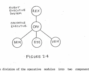
are sepa.rate concurrent processes, hierarchically structured as shown in the Figure 2.3 [Srinivas 73a, 7~b, Stevens 74, Roth 75].
Figure 2.3 shows the actual division of the modules between two different computer installations. The software on the PDP 10 is largely written in SAIL [Vanlehn 73] , while the software for the SPC 16 at JPL
is written in FORTRAN. Each of the modules on the PDP 10 is implemented as a separate job. Communication between jobs is achieved through a message passing mechanism called MAILER.
RD130\ c'Y-E.CV'f1vE
SYS1G:.M
OPE\'Z.Ail\JE t;,.'1(£C..U(1Vf..
Fl G URE '2·.4
Note the division of the operative modules into two components. The details of Figure 2.3 will be largely ignored in the subsequent sections of this report, and the more abstract structure of Figure 2.4 will be used. The components of this figure will be described in
[image:33.617.179.528.288.567.2]2.5.1 Robot Executive System
l
REXl
REX serves as the interface between the human supervisor and the
rest of the robot software. Such an interface is necessary because the robot is not a completely autonomous system, and ultimate control resides in the human supervisor. The supervisor is thus provided with a set of commands to control and monitor the activities of the in~egrated system. One of the design requirements is that REX be almost
irrunediately responsive to the human supervisor. It is for this among other reasons that REX is a separate process running concurrently with the rest of the robot software.
Through REX the human supervisor can interact with the robot in the following ways. He can:
(1) Create, edit and delete plans. A plan editor is incorporated as part of REX.
(2) Request execution of plans and abort plan execution.
(3) I:etermine the status of the system to many levels of detail. (4) Trace the flow of control and data between the different modules.
2.5.2 The Operative.Executive
J.
OPX.L
The operative modules are individually responsible for the specific functional capabilities of the robot. To achieve a collective effort these modules are integrated by means of OPX. OPX achieves this by invoking primitive actions
order specified in a plan. execution of plans.
Plans are structured sets of action units or other plans. language allows for concurren~ execution of action units different operative modules through a CCBEGIN-COEND feature.
The plan in the However, we will restrict plans to sequential list of actions in this study. Each action unit specifies the operative module to be invoked and the specific action routine to be called. OPX sends to the appropriate operative module a message requesting the execution of a primitive action.
en
completion of the action, OPX continues with plan execution by repeating the above process with the next action unit. When the plan has been successfully executed a completion message is sent up to REX.During execution of the plan OPX is still responsive to rressages from REX. OPX can therefore determine the status of the operative module, abort the plan, or turn on tracing, so that the flow of control becomes explicit to the user.
2. 5. 3 The Operative Modules (ARM, EYE, and ROVER)
action capabilities of the
The operative modules implement primitive
robot. 'llle implementation is termed an action unit, and a primitives on which more collection of such action units defines the
complex plans are based.
(1) ARM MO VETO
The MOVE'I'O action unit takes the manipulator from its current location to the specified goal position. In doing so it has to find a trajectory such that collisions are avoided. 'lbe manipulation system implemented by I.ewis[74] includes a simple collision detector, but the system is likely to show markedly improved capability with the integration of the software developed by Udupa[76]. Udupa's solution is based on a theoretical framework which makes the task of collision detection and avoidance computationally tractable.
Once the trajectory has been determined, the joint angles need to be determined as a function of time, so that the manipulator will trace the desired trajectory.. 'Ibis again is a fairly complex task involving both kinematics and dynamics of the manipulator. I.ewis[76] has implemented a very elegant solution to this problem. (2) EYE : LOCATE
(3) Rover : GOro
For the robot to be mobile,. a path planning algorithm [Udupa 74,
Thompson 75] is necessary. Given a description of the environment,
the -path planning algorittun finds a safe route to the goal
location. The GOro action unit then takes the vehicle along the
planned route. 'Ihe real time control of the vehicle is an
extremely difficult problem especially in uneven and hazardous
terrains. A first version['Ihompson 76] of such a real time
controller and a path planner is now capable of moving the vehicle
around in a relatively flat environment in which rocks of various
sizes are strewn around.
2.6 EXAMPLE OF EXECCJrION
Consider a simple plan called PICKUP with the following structure:
(rock) BEGIN
LCX:ATE (rock);
MOVE-HAND-'1'0-GRASP (rock); GRASP (rock)
END
(We will use the convention that identifiers in lower case letters are
uninstantiated parameters.} The human supervisor starts things rolling
by corrunanding REX to execute the plan PICKUP with the parameter RCCKl.
The plan is instantiated (with ROCKl for "rock") and then sent to OPX
OPX begins execution by invoking vision to UX:ATE RCA':Kl. This
results in a TV picture being taken. 1l1e picture is digitized and then
segmented. ROCI<l i.s identified in the segmented image and the vision
system then builds a three-dimensional model of the rock. A descriptor
of ROCKl is returned which contains information about its location,
width, height, support level, etc.
On receiving a completion message from the EYE operative module,
OPX sends the next action unit to the ARM module. With the newly
updated data for ROCKl, the ARM module determines an orientation for
positioning the hand around the object. Trajectory computation is
performed and the ARM executes the trajectory. A COllll?letion message is
then sent to OPX. OPX continues execution by sending the GRASP action
unit to the ARM module. 'Ihe ARM module· executes GRASP. The completion
message from this action unit signals plan completion. OPX sends a
message to REX with this information.
2.7 ERRORS AND A MODULE FOR ERROR RECOVERY
- - -
---
- - - --
--··
-The execution of the plan PICKUP(ROCKl) described in the previous
section assumes that every action succeeded in achieving its goal.
Consider a case in which the hand bumps onto the object, instead of
being correctly positioned around it. On detecting such an error, the
ARM module sends an error message to OPX. OPX terminates plan execution
by aborting the plan. An error message is sent up to REX, and the human
OPE.R.Al I LJ r=
F-Y. e.. cu
n
v £FtGLJR.f-
2·5
Mopu Lr;
Fot<..
E~i<..of(.. 1<..Ec ovrz ~·Y
The goal of this thesis is to automate recovery from such failures.
For this puq:ose a module called MEND has been implemented and its olace
in the robot structure is shown in Figure 2.5. The following chapters
will describe MEND's capabilities and its internal structure. To
illustrate the techniques used by MEND in planning recovery from
failures, several scenarios dealing with the Hand-Eye subsystem of the
A DESCRIPrION OF M&l\JD
3.1 INTRODUC'rION
In the previous chapter the need for a recovery system like MEND
was explained. The relationship of MEND with other modules of the JPL
robot system was briefly described. In this chapter we take a look at
its internal structure. This chapter also describes the representation
of knowledge about actions, the world model, the interpretation and
execution of actions, updates to the world model and other details of
MEND.
In its initial conception, MEND was expected to come into play only
when a failure was detected. We can depict such a relationship as shown
in Figure 3.1.
[t:.~ROIL M£-<"..S1.6f:.]
---~
Rof3.o..,-~)c ECvfl
VF-<;yS1~tv\
F\GURE 3.1
CX< l\NG~:S ltJ 'fKE
Tasks or goals are specified to the robot executive system which
translates these into actual changes in the real \'K>rld. If a failure is
detected during execution of the task, then MEND receives an error
message describing the failure. MEND responds to this by analyzing the
failure and suggesting appropriate corrective steps. These corrective
steps are structured into a recovery plan which is then sent over to the
executive system.
Tne first version of MEND that was implemented reflected this
initial idea. Its limitations provided a major motivation of the system
as it exists now. Among other things it became clear that there was a
need for a much more intimate relationship between the execution of
plans and the analysis of failures. 'Ihe second version of MEND plays a
much more important role in the system. The description in this report
is a conceptualization of this second version.
3. 2 THE INTERNAL STROCTURE OF MEND
- -
-- - - ---
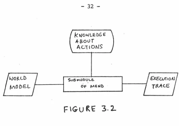
-----MEND consists of many parts which interact together to execute
plans, recover from failures etc. Every computation in MEND has access
to three entities and these are shown in Figure 3. 2. Knowledge about
actions is built into the system and is not modified by any computation.
'Ihe world model represents the current state of the \'K>rld and the robot.
The execution of actions results in utx'lates to the \'K>rld model to
reflect the changes in the real \'K>rld. Tne execution trace represents
IVOfU .... D
fv\O DE..L
k tl/OWL.E: DG f
A-Bour Ac...11otJS
$v6 ""-Ol>U\-E..
or
fl.l\E t.ibis to be executed next, what previous action failed, what corrective
actions were taken, etc. 'Ihese entities are discussed in more detail in
later sections.
3.2.1 Execution of plans with MEND
At first we ignore the problem of error recovery and merely
consider the execution of plans. Figure 3.3 indicates the flow of
control between the different computations in MEND, and the tVK> major
states that MEND can be in when quiescent.
Some notational conventions are first described. Circles represent
states and rectangles represent computational processes. Transitions
from a state are activated when a message is received. Messages
received by MEND are enclosed in square brackets with the sender being
identified as a prefix to the message. A process can have several
outcomes and can lead to other states or processes. Typically when a
[image:42.615.145.488.61.303.2]PLAIJ-(IJl TIA-TOR.
f\C{IQN- I/JI TIA-TOR.
These messages are enclosed in circular brackets, the receiver being identified as a pref ix to the message.
goes into the EXECUTE state. When MEND receives a completion message,
ACTION-COMPLETOR checks that the results are as expected, updates the
world model, updates the plan status and then transfers control to
AC'rION-INITIATOR i f there are more actions to be executed. Typically a
cycle of ACTION-INITIATOR's and ACTION-CCMPLE'I'OR's will sequence through
the plan until execution of the plan is completed. When this occurs,
PIAN-Ca1PLETOR cleans up the execution tr ace and returns MEND to the
IDLE state.
3.2.2 MEND with error recovery
Mo A
(t•H rurj
.DEC \DER
FR.A
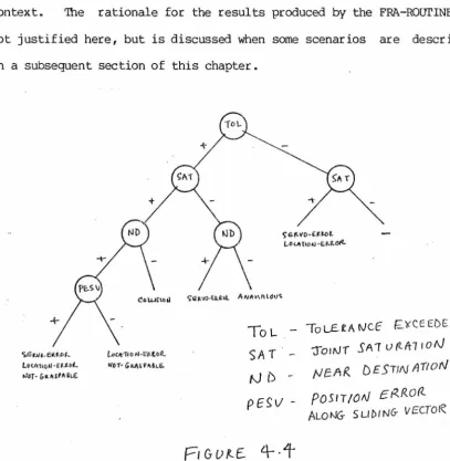
3.4-MEND, as represented in Figure 3.3, monitors the execution of plans by checking preconditions before executing actions and by checking postconditions to ensure that actions have been performed correctly. 'Ihe figure does not indicate what MEND does when these checks fail or if an error message is generated by an operative module as a result of executing an action. Figure 3.4 answers this issue.
We can immediately note from Figure 3.4 that there are two ways in which failures are detected and control can be transferred to FRA, the failure reason analyzer. 'l'he path from the state EXECUTE to FRA represents those situations where failure is detected by the primitive actions. It is not always possible to rely on the primitives to detect the failure since failure is meaningful only in the context of the specific way in which the primitive is being 'used. These failures are detected by ACTION-COMPLE'IDR which has knowledge about the post-conditions of the actions interpreted by MEND.
'Ihe checking of preconditions, which is done as part of the ACTION-INITIA'IDR, is a way of anticipating and avoiding failures during execution. If the preconditions are found to be false, the PLAN-PATCHER is called to achieve these preconditions. If they have been only partially verified then these are marked as being UNVERIFIED in the execution trace, and execution is allowed to continue. (This will be explained in greater detail.)
FRA, DECIDER, flU and PLAN-PA'D:HER perform responsible for handling recovery from failures. failure and finds one or more ex?lanations for the
provides a means of integrating failure reason analysis with multiple
outcome analysis. In cases where the failure reason analysis has
provided a simple solution for planning recovery, DECIDER transfers
control to the PIAN-PA'D:HER. Otherwise, MOA is called. In analyzing
multiple outcomes MCli\ may find that the available information is
inadequate. In such circumstances MEND resorts to model-driven
information gathering by asking for execution of simple actions, and
going into an ACQUIRE state. On completion of the information gathering
step, multiple outcome analysis is continued. When analysis is complete
the PIAN-PA'.ICHER is called with the results
ot
the analysis.PLAN-PATCHER uses the results of the analysis to find a set of
corrective steps and patch the plan in execution.
3. 3 WORLD MODEL
'Ihe state of the world is represented in MEND through a set of data
structures that will be collectively referred to as the 'M'.)rld model.
Typically, other systems model the world in terms of assertions
represented as lists of items. MEND's representation is much more
structured and tailored around the entities that it needs to deal with.
The advantage of this is ease of accessing and efficiency of
implementation, with the associated disadvantage of non-uniform
procedures for accessing and updating the data base. Accessing of the
world model occurs in several ways. ACTION-INTERPRETER needs to use
information about the location and orientation of objects in
INTERPRET-ROurINE associated with actions is programmed to access the
world model to determine such information. In other words, knowledge
about the way in which data are represented in the world model is built
into these procedures.
Another set of procedures that access the world model are the
INITIATE-ROurINE's. These routines check preconditions and constraints
applicable to the action with which they are associated. In MEND
checking of preconditions and constraints is somewhat different from
traditional robot problem solving systems. We illustrate with an
example. C.onsider the precondition WITHIN-GRASP (ROCK) for GRASP (ROCK).
'Ihe INI'rIATE-ROurINE for GRASP will check that the hand position is
within a small tolerance limit of the known location of the ROCK. If
this check fails, then the precondition will be considered to be false.
However if this condition is found to be true, MEND recognizes that this
precondition may still not be true because of J;>OSsible inaccurate
information about the location of the ROCK. If in addition, though,
MEND finds that the touch sensors in the hand are activated, then it
will consider WITHIN-GRASP to be true. The main J;>Oint to be noted is
that precondition . testing is not equivalent to looking for an
appropriate assertion in the world model, or to deducing this from other
assertions.
A third set of procedures, the FINISH-UP-ROurINES associated with
There are four entities about which information needs to be
represented, and they are the state of the hand, objects, stations and
frames. We discuss each of these in turn.
HAND COORDINATE FRMIE
71.
Am.011rnvE"croR-~ SL.1 t>i'1G vec.,DR.
NO!lNIAL VELT~
1-£.FT F"I NG ER. F.1c11r FtMc.E:R.
\_, BASE COORDINATE FRAME
~6 "'-....
zo
m
p"·
FlG-URE 3.5
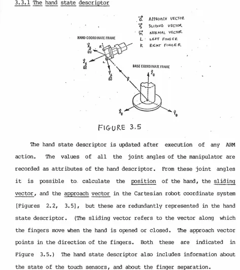
'!he hand state descriptor is updated after execution of any ARM
action. The values of all the joint angles of the manipulator are
recorded as attributes of the hand descriptor. From these joint angles
it is possible to. calculate the position of the hand, the sliding
vector, and the approach vector in the Cartesian robot coordinate system
[Figures 2.2, 3.5], but these are redundantly represented in the hand
state descriptor. (The sliding vector refers to the vector along which
the fingers move when the hand is opened or closed. '!he approach vector
points in the direction of the fingers. Both these are indicated in
Figure 3.5.) The hand state descriptor also includes information about
[image:48.612.64.537.200.731.2]In addition to the above data, additional information is stored as
part of the hand state descriptor. An attribute called GRASP-STATE
indicates whether the hand is holding an object, touching an object, or
whether the hand is empty. Another attribute, the GRASP-HEIGHT records
the z coordinate of the hand whenever an object is grasped. This piece
of information is useful in determining how far above the station the
hand should be when attempting to place the grasped object at a desired
location.
3.3.2 Object descriptor~
Each object is represented as an item in the data base, and is
described by various attributes. 'Ihe vision system estimates the
location of the object from a stereo view of the scene with additional
information from the laser system in some cases. It also estimates an
orientation of the object (the axis of the longest dimension), the
grasping direction, the width along the grasp direction, and the height
of the object, the support level, and other such details. All these are
represented as part of the description of the object. In addition to
these an attribute called ABSTRACT-LOCATION indicates whether the object
is at a station, in the robot's hand, or whether the fingers are merely
touching the object. 'lhis information is useful in testing
pre-conditions and also in interpreting the attributes of an object in a
meaningful manner. For instance, i f the object has been gras~d, then
the location of the object is determined from the hand position and not
from its LOCATION attribute. A point to note about the representation
ABSTRACT-u::x:ATION indicated that the object is in the robot's hand, the
GRASP-ST.~TE of the hand will alse indicate that the robot is holding the
object. This redundant description makes it convenient to get the
necessary information directly rather than by an associative or pattern
directed search.
3.3.3 Station descriptors
Stations provide a means of naming some designated locations.
These locations can either be on the ground or on the robot platform.
Station O::::CUPAN:Y indicates whether or not there is
an
object at thestation. This will be checked, for instance, before an object is
transported to the station to be placed there. A
STATION-TOLERANCE-LIMIT can be specified and later used in determining
whether a placement of the object at the station is within acceptable
limits.
3.3.4 Frame descriptor
A frame defines the position, sliding vector and approach vector of
the hand, and is useful in specifying intermediate configurations when
the hand moves from one location to another. With a good obstacle
avoider built into the manipulation system it should be possible to
eliminate this low level of dealing with hand configurations.
they are necessary in the current system to avoid obstacles.
3. 4 KNOOLEDGE ABOUT ACTIONS
The implementation of ARM, EYE, and VEHICLE provide higher levels
of the robot system with action primitives. These primitives can be
used to achieve various results. For instance, the primitive MOVETO
which can move the hand from one position to another, can be used to
position the hand around the object or to transport the object from one
position to another. In the first case, it would be reasonable to check
that the hand is empty before begining execution of the action, while in
the latter case it is necessary to verify that the object to be
transported is in the hand. Modelling of actions directly in terms of
these primitives is difficult because of the different conditions that
apply in different circumstances.
MEND thus models a slightly higher level set of actions which are
specialized for different functions. MOVE-HAND-TO-GRASP(object), for
example, is· a specialization of MOVETO with the implicit pur!;X)se of
positioning the hand around the object to be grasped. When the human
specifies a task by writing a plan composed of these higher level
actions there is an implicit notion of its intended effects. It is this
notion of purpose or intent that makes it lX)ssible to recover from
llJIT/l'rT[·
fl.oOTINE
D
/NTekP!.E.r·E RoC/TtlV€
c.
tv\L 0 A
·~ [)
ACTION
FINISH·UP·A E Rourtt.JE
T L I
v
FttA·E R.oUT/NE
MoA~
R.o/JWJ~
FIG
UR.E
3 .6
Each action is represented in MEND as an item in the data base, and
has both a declarative and procedural component[Figure 3.6]. Tne
declarative model is represented as triples in an associative data
base[LEAP data structures in SAIL - Vanlehn 73], and a triple (A IV) is
interpreted to mean that attribute A of item I has value V. A partial
description of the declarative model of MOVE-HAND-TO-GRASP is shown
below:
(ACTION-TYPE MOVE-HAND-To-GRASP(ROCK) EFFF.cTOR)
(PRE.cONDITION MOVE-HAND-TO-GRASP (ROCK) (EJl1Pl'Y-HAND))
(PRECONDITION MOVE-HAND-TO-GR~SP(ROCK) (OPEN-HAND))
(NEEDED MOVE-HAND-'l'O-GRASP (ROCK) LO:ATION (ROCK))
[image:52.615.166.484.67.335.2]This model represents the fact the MOVE-HAND-TO-GRASP is an
effector action, that it has a par~neter called RO:K, that one of its
pre-conditions is EMPI'Y-HAND, that the location of the Ro:K is needed
information, that its intended result is WITHIN-GRASP(RO:K), and so on.
'lhe procedural component consists of an INITIATE-ROITTINE, an
INTERPRET-ROurINE, FINISH-{JP-ROurINE, a FRA-ROurINE, and a MOl\-ROurINE
associated with the action [Figure 3. 6]. ACTION-INITIATOR for
instance, calls the MOVE-HAND...JI'O-GRASP INITIATE-ROITTINE to check
parameter types and preconditions.
Let us now take a brief look at the actions that have been modelled
for demonstrating error recovery in simple manipulation tasks.
3.4.1 ARM actions
(1) MOVETO(frame)
This action defines the most primitive caµability of the
manipulator to move from one location to another. 'I'he parameter of
MOVETO specifies the desired absolute position and orientation of
the manipulator. This action is not directly modelled in MEND but
the following specializations of this action are.
(la) MOVE-HAND...JI'O-GRASP (object)
The expected result of this action is to position the hand such
that the fingers surround the specified object. The initiation
routine will check that the hand is empty, that the fingers are
determines a position and orientation which is appropriate for
grasping the object. In general this could be a difficult problem
requiring a good understanding of the shapes of objects and the
resulting constraints on how the object can be grasped. However,
for the simplified world that MEND is being tested in, this is
relatively straightforward. In fact, a grasp orientation is
suggested by the vision system.
(lb) MOVE-HAND-TO (frame)
The only difference between this action and the primitive MOVETO is
that the INITIATE-ROUrINE will check that there is nothing in the
hand.
(le) APPROACH (object)
Sometimes it is necessary to position the hand near the object so
that the location of the object can be determined relative to the
hand. This action positions the hand at a point some small
distance above the object. 1he INITIATE-ROurINE will check that
the hand is not holding any object.
(ld) TRANSPORT (object, station)
An object which has been grasped can be transported to a station
where it is to be placed. Preconditions that are checked ensure
that the object is the hand, and that the station is unoccupied.
The INTERPRET-ROurINE will use the information recorded in the
hand position which will result in the object gently bumping onto
the desired station. The FINISH-UP-ROUrINE will check that the
station tolerance limit is not exceeded.
(le) MOVE-OBJECT...!JD (object, frame)
This is similar to MOVE-HAND-'"l'O except that in this case an object
is expected to be in the hand.
(2) SEPARATE(finger!separation)
This action results in the fingers being opened (or closed) to the
desired finger
s pee ial i za tions •
(2a) GRASP(object)
separation. This action again has several
Execution of this action results in the object being grasped
provided that the fingers have been positioned around the object.
'lhe motors driving the fingers are kept active for a short period
of time even after the object has been sensed by means of the touch
sensors. 'lhis is done so that the hand gets a firm grip on the
object. The INITIATE-ROUTINE will check that the position of the
hand and the known position of the location of the object indicate
that the object is WITHIN-GRASP. However, this test does not
guarantee that the object is really within grasp because of
possible errors in the location of the object. The
FINISH-UP-ROUTINE will update the ABSTRACT-LOCATION of the object
GRASP-STATE and GRASP=-HEIGHT attributes of the hand descriptor are
also updated.
(2b) CLCSE!UNTIL!TOUCH(object)
'Ihis is similar to GRASP. However the fingers stop moving the
moment the touch sensors are activated. Often it is a good
heuristic to gently close the fingers around the object and then
squeeze tight in order to GRASP the object. After execution
ABSTRACT-LOCATION will merely indicate that the hand is touching
the object.
(2c) LE']X;Q(object, station)
This merely SEPARATES the fingers to release the object. It
verifies that there is an object in hand and that hand is at the
station. 'Ihe FINISH-UP-ROurINE will change station OCCUPANCY to
occupied, updates the ABSTRACT-I.CX::ATION of the object to indicate
that it is AT(station).
3.4.2 EYE action units
(1) UX:ATE (object)
This action assumes that the object has been identified either by
specifying an approximate location, or by certain distinguishing
features of the object. A new descriptor is created by the
FINISH-UP-ROurINE and the different attributes updated with the
( 2) LCCATE-REIATIVE-TO-HAND (object)
On occasion it is necessary to determine the position of an object accurately. Part of the difficulty in determining the location accurately is the discrepancies between the hand coordinate system and the eye coordinate system. To avoid this problem the hand is
brought close t.o the object, and the location of the object determined relative to the hand. As with locate, UX::ATE-RELATIVE...JI'O-HAND updates data structures describing the object.
3. 5 THE EXECUI'ION TRACE
A new execution trace is created by PLAN-INITIATOR whenever a new plan is to be executed. It starts off as a set of ncrles strung together to represent the plan to be executed. Each node is associated with an action and its parameters. A NEXT-TO-BE-EXECUTED pointer indicates which action is to be executed next. An example of an initial structure
is shown in Figure 3.7.
Several things get added to the trace as execution proceeds.
Before beginning execution of an action, the INITIATE-ROUI'INE will mark all unverified preconditions and constraints by creating triples of the form:
After successful execution, the NEXT-TO-BE-EXOCUTED p::>inter is
moved ahead to the next node. If failure occurs and PLAN-PATCHER
successfully finds a recovery plan, it will modify the execution trace
by creating new nodes for the action to be executed.
for failure in ~DE-B of Figure 3.7, corrected by a
'Ihe new structure is shown in Figure 3.8.
We show an example
After execution of the recovery plan, execution will continue with
FAILURE REASON Al\lALYSIS
4.1 INTRODUCTION
MEND uses two different strategies for recovery from failures. In
this chapter we discuss how ME'ND analyzes failure and how the results of
this analysis are used in planning recovery. Let us first take a look
at a classification of failure reasons.
4.2 A CIASSIFICATION OF FAILURE REASONS
MEND's analysis of failures reflects an understanding of four kinds
of failures. These are operational errors, information errors,
precondition errors, and constraint errors. We discuss each of these in
turn.
Actions can fail to achieve their intended result because of
certain inherent problems in executing the action. These errors are
peculiar to the specific operation being performed and are therefore
referred to as operational errors. We can see a number of examples of
these kinds of errors in the JPL robot. For instance, the manipulator
may deviate from the planned trajectory in moving from one location to
another. 'Ibis operational error of servoing will not often have any
serious consequences, but in some cases it can cause the manipulator to
The process of determining the location of objects is subject to
several operational errors. Calibration, resolution limits, noisy data
and other such reasons are all contributing factors in producing
erroneous information. For our purposes there is no need to distinguish
between them, and we will deal with them collectively as a single
operational error. There is the possibility of confusion here, and we
reiterate that the operational error does not refer to the inaccuracy in
the location. This inaccuracy is a consequence of the operational
error.
If the robot fails in positioning the hand correctly around the