LICENSE PLATE RECOGt ITIO SYSTEM USING VlDEO AND 1MAGE
MAZREE BfN IBRAHIM MAASPALIZA BfNTI AZRI
AZRITA BfNTI ALIAS
SALEHA 81 Tl MOHAMAD SALLEH
RESEARCH VOTE: P JP/2006/FKE( 12)S21 0
FAKULTI KEJURUTERAAN ELEKTRIK UNIVERSITI TEKNIKAL MALAYSIA MELAKA
II
ACKNOWLEGDMENT
First of all. I would like to thanks to our sponsor UTeM. secondly to our dean. Engr. Profesor Dr. Marizan bin Sulaiman and deputy dean (research) Dr. Hamzah bin Sakidin, and my head of department, Mr Hyreil Anuar bin Kasdirin, my co-researchers. take this opportunity to extend my deepest gratitude to all those who have assisted me in making this project and report successfully.
My sincere thanks also to all those who have assisted me in making this project and report successfully.
Ill
ABSTRACT
The purpose ofthis project was to build a real time application which recognizes license plates from cars at gate, for example at entrance of a parking area. The S) stem. based on regular PC vvith video camera. catches video frames which include a visible car license plate and processes them. Once a license plate is detected. its digits are recognized. displayed on the User Interface or checked against database. The focus is on the design of algorithms used for extracting the license plate from a single image. isolating the characters of the plate and identifying the individual character. Image sample of vehicle's license plate is acquisited by video camera. then. it is converted into Black and White (BW). Artificial eural Network (ANN) is applied to recognize the character's plate. Learning method of the ANN is back propagation and all process is
I\
ABSTRAK
CONTENTS
CHAPTER CONTENTS PAGE
I
II
PROJECT TITLE
ACKNOWLEDGEMENT ABSTRACT
CONTENTS
LIST OF APPENDIX
LIST OFT ABLE
LIST OF FIGURE
LIST OF ABBREVIATION
INTRODUCTION 1.0 Introduction
1.1
1.2
1.3
Objective
Problem Statement
Scope Project
LITERATURE REVIEW
II
III-IV V-VIII VIII
IX X
XI
2 2 3
2.1 Purpose statement for Neural Network approach 4
2.2 Artificial Neural Netvvork 4-5
2.3 Recognition 5-6
III
IV
THEORY
3.1 Chapter Overvie\\
3.2 Malaysian Vehicle License Plate .., "''
.) . .) Basic design of license plate 3.4 Software R2006a
3.5 Definition of Image Processing 3.6 What is Neural etwork
3.6.1 Multilayer Perceptron (MLP) 3.6.2 Neural et\ ork element 3.6.3 Neural Netvvork Architecture
METHODOLOGY
4.1
4.2 4.3
4.4 4.5
Chapter Overview
Development of program codes Capturing image
4.3.1 GUI (Graphical User Interface) for capturing image
4.3.2 Video Setup 4.3.3 Previewing video 4.3.4 Capturing images
Recognizing character on the car plate Simulink
4.5.1 Part I: Image acquisition and object Recognition
8
8
9
9-10 10
11-12 12-13 13 14
15 15 16 17-18
18-19 20 20 20
21 21-24
4.5.2 Part 2: Design the progression of the system 24-25 4.5.3 Part 3: Description ofthe implementation 26
4.5.3.1 License plate extraction 4.5.3.2 Black region extraction
26
4.6
4.5.3.3 Dilating black regions 27 4.5.3.4 Determining the angle of the plate 27 4.5.3.5 Improved license plate region 28
4.5.3.6 License Plate Crop 28
4.5.3.7 License Plate Quantization and 29 Equalization/ converts RGB image to B W
4.5.4 Part 4: Developed Simulink.model 29-30
Neural Network 31
4.6.1 Part I: Design character recognition of 31 alphabet and number
4.6.2 Part 2: Training and recognize the character 31-33 4.6.2.1 Initialization 33 4.6.2.2 Training
4.6.2.3 Training without noise 4.6.2.4 Training with noise
33 34 34
4.6.3 Part 3: Training aNN for classification 35
4.6.3.1 Read the image 4.6.3.2 Image Preprocessing
4.6.3.3 Creating Vectors data for the Neural Network (objects) 4.6.3.4 Creating and training of the
Neural Netv ork
4.6.3.5 Testing the Neural Network
35 35 35
36
36
4.7 Using GUI (Graphical User Interface) 4.8 Assemble
37-42 42
4.9 Gantt Chart 43
V RESULT
5.1 Capturing image using \\eb camera
5.2 Result from RGB image 5.3 Neural etwork
5.4 Noisy letter A to Z and the network recognize the character
5.5 Error for network to recognize 5.6 oisy letter I to 9 and the net\ ork
recognized the character 5.7 GUl
VI DISCUSSION AND SUGGESTION
6.1 6.2
Discussion and Conclusion Suggestion
VII CONCLUSION
7.1 Conclusion
REFERENCES
APPENDIX A APPENDIX B APPENDIX C
CAPTURING IMAGE
NEURAL NETWORK GUT
44-45 45-46
46 47-54
55 56-58
59-63
64 65
66
67-68
69 73 84
IX
LIST OFT ABLE
NO. TITLE PAGE
LIST OF FIGURE
NO. TITLE PAGE
2.1 Some graphics of transfer function 5 2.2 Extraction of a character in a matrix 7 2.3 Identification of background and character. 7 3.1 A graphical representation ofan MLP 12
3.2 Training process 13
3.3 Neural Network architecture 14
4.1 Block diagram show 2 methods in this project 15 4.2 Block diagram shO\ sequence method for capturing image. 16
4.3 Command window 17
4.4 Guide Quick Start 17
4.5 Create figure using button 18
4.6 Create figure using 3 pushbut1on and I axes 18
4.7 Command window for adaptor 19
4.8 Block diagram show the sequence method of recognizing 20 4.9 Block diagram show the sequence method ofSimulink 21 4.10 Image Acquisition block-mask parameters 22 4.11 Color Space Conversion block-mask parameter 23
4.12 Autothreshold block parameter 24
4.13 Block diagram of the system 24
4.14 Block diagram of license plate extraction and character
Segmentation 25
4.15 Example of captured frame 26
4.16 Captured frame with black region dilated 27
XI
4.18 Improved License Plate region 28
4.19 License Plate Crop 28
4.20 Gray scale input license plate 29
4.21 Overall Simulink Program 30
4.22 Overall Program for Neural etwork 31
4.23 Alphabet A without noise 32
4.24 Alphabet A with noise 32
4.25 Block diagram of the sequence method using GUI 37
4.26 Design the dra\ ing using axes. panel button and
pushbutton 38
4.27 Save and Run the M-file 39
4.28 Block diagram ofthe sequence method using
pushbutton load 39
4.29 Block diagram ofthe sequence method using
pushbutton select. 40
4.30 Block diagram of the sequence method using
pushbutton pre-process 41
4.31 Block diagram of the sequence method using
pushbutton extract 41
4.32 Block diagram of the sequence method using
pushbutton recognize 42
5.1 Setup the adapter using pushbutton video setup 44
5.2 Choose the best pixel 44
5.3 Capture image using pushbutton snap 45
5.4 Video Viewer 45
5.5 Video Viewer I 45
5.6 Video Viewer 2 46
5.7 Video Viewer 3 46
XII
5.9 Training" ith noise 46
5.10 Alphabet A 47
5. I I Alphabet B 47
5.12 Alphabet C 47
5.13 Alphabet D 48
5.14 Alphabet E 48
5.15 Alphabet F 48
5.16 Alphabet G
49
5. I 7 Alphabet H 49
5.18 Alphabet I 49
5.19 Alphabet J 50
5.20 Alphabet K 50
5.21 Alphabet L 50
5.22 Alphabet M 51
5.23 Alphabet N 51
5.24 Alphabet 0 51
5.25 Alphabet P 52
5.26 Alphabet Q 52
5.27 Alphabet R 52
5.28 AlphabetS 53
5.29 Alphabet V 53
5.30 Alphabet W 53
5.31 Alphabet X 54
5.32 Alphabet Y 54
5.33 Alphabet T 55
5.34 Alphabet U 55
5.35 Alphabet Z 55
5.36 Alphabet I 56
XIII
5.38 Alphabet 3 56
5.39 Alphabet 4 57
5.40 Alphabet 5 57
5.41 Alphabet 6 57
5.42 Alphabet 7 58
5.43 Alphabet 8 58
5.44 Alphabet 9 58
5.45 Chose image 59
5.46 Load image 59
5.47 Select character 59
5.48 Pre-Process the image 60
5.49 Extract the image using Neural Network 60
5.50 Recognize number 0 60
5.51 Recognize number I 61
5.52 Recognize number 2 61
5.53 Recognize number 3 61
5.54 Recognize number 4 62
5.55 Recognize number 5 62
5.56 Recognize number 6 62
5.57 Recognize number 7 63
5.58 Recognize number 8 63
1. NN
2.ANN
3. GUI
4. LPR
5.MLP
LIST OF ABBREVIATION
= Neural Network
=Artificial Neural Network
= Graphical User Interface
=License Plate Recognition System
= Multilayer Perceptron
CHAPTER
I
INTRODUCTION
1.0 Introduction
The number of vehicle in metropolitan cities is always growth. The growth
has a positive implication to provide a professional and sufficient parking system.
This fact requires a plate number recognition system to support a parking
arrangement.
The aim of this final project is to develop Simulink Model of License Plate
Recognition system using Sirnulink, Video and Image Processing Block set R2006a
(software).
License Pate Recognition system (LPR) is an image-processing technology
used to identify vehicles by their license plates number. LPR project is to present a
real time car park control system. A video-based car park model will be built by
using Simulink of Video and Image Processing Block set to capture the license plate
number.
The proposed of this License Plate Recognition system (LPR) works,
whenever the vehicle approached the secured area (Entrance). The sensor senses the
car and its presence signaled to the LPR unit. After that, the LPR unit activates the
illumination (lnfrared) and takes pictures of the front plates from the LPR camera.
The images of the vehicle include the plate and the pixel information is read by the
LPR unit's image processing hardware. Then, the LPR unit checks if the vehicle
appears on a predefined list of authorized cars compare with the database, and if
found, it gives signals to open the gate. Next, the authorized vehicle enters into the
secured area. After passing the gate, its detector closes the gate. Now the system
waits for the next vehicle to approach the secured area. The same process will be
2
1.1 Project Objectives
The objective of the project proposal:
I. To develop Simulink Model of License Plate Recognition System using Video and Image Processing Block set
(software).
2. Capturing images (license plate number)
3. Training character of the license plate number
4. Recognized the character of the license plate number.
1.2 Problem Statements
Nowadays parking lots are becoming organic part of our everyday life. We
use the entrance, day by day when going to work, shop, a hotel, a restaurant, an
airport, a hospital etc. But, for people who are living in private area like in
condominium, they have to wait for guard to open the gate before cars can enter the
entrance. Parking our car, leaving it in safe, finding it there again. fast, comfortably and easily, that's the goal. To reduce time. increase efficiency and security, that's an
important issue. License plate recognition system using video and images offers flexible, low maintenance, yet effective and intelligent technology for car park
operation: ticketing, security, location services, etc.
With integration of license plate recognition system using video and images into parking management systems in private area, it becomes possible to automate
vehicle entry to and exit from a car park or a secure zone and to use the recognized registration number for inventory management. The usage of license plate recognition with specially designed camera set, equipped and synchronized with a
3
1.3 Scope Project
The scope of this project using Simulink, Video and Image Processing Block
set R2006a (software) are:
I. Used the system for private area only such as in condominium
2. Capture the license plate recognition.
3. Takes picture of the front plate
4. Train the alphabet (A to Z) and number (0 to 9) using neural
network.
4
CHAPTER II
LITERATURE REVIEW
This chapter reviews existing project created to get an idea about the project
design, conception, specification and any information that related to improve the
project. In this chapter, some review about an Artificial Neural Network system that
proposed to fulfill this project will also be reported.
2.1 Purpose statement for Neural Network approach
Tim Klassen [I] as mentioned in the introduction, this research will show
on-line average Arabic character recognition rates above 80% and training recognition
rates above 90% using Neural Networks for feature extraction and classification with
multiple unconstrained 19 writers. Linear networks will be emphasized, where this
represents the lowest computational overhead during both training and recall, hence
suitable for the target application device.
2.2 Artificial Neural Network
Haris Al-Qodri Maarif, and Sar Sardy [2] mentioned that Artificial Neural
Network (ANN) is a network which imitate to human neural network with some
simple processors (units). Each unit has some local memory and connected
unidirectional to flow the numerical data. Those units are operated only at local data
5
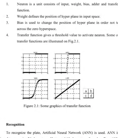
I. Neuron is a unit consists of input, weight, bias. adder and transfer
function.
2. Weight defines the position of hyper plane in input space.
3. Bias is used to change the position of hyper plane in order not to
across the zero hyperspace.
4. Transfer function gives a threshold value to activate neuron. Some of
transfer functions are illustrated on Fig.2.1 .
I I I " - - 1 - - -1- - -1
-1 I I
" - -t - --I---~--
-I I I " - -r - -~---~--
-t : - - : -- -:- - -:- -
---~
--I I
to - - , - ---~
--c: __ 1 __ -1 ___ 1 __
I I I
-!
...
I lo I
<! --:---~--:--
-1 P I ' - - r --~ --~--
--<1 - -~-
J
___
:
_--0 I 01 I
"
_JJU
..E..L!J
Figure 2.1: Some graphics of transfer function
2.3 Recognition
To recognize the plate, Artificial Neural Network (ANN) is used. ANN IS
designed to recognize 26 characters of letter and I 0 characters of number. Two ANN
topology are designed to recognize letter and number. The designed ANN is a back
prop network (supervised learning), which is able to recognize input matrix in size
1326 x n. Designing of ANN is conducted by applying function newff. ANN has
three layers consisting of input layer, hidden layer and output layer. For ANN's
number, there will be 10 neurons for hidden layer and output layer. For ANN's letter.
[image:19.501.60.456.35.498.2]6
Target for the ANN are 26 elements for ANN's letter and 10 elements for
ANN's number. The value of element of each targets are all zero except one element
on specific position which represent the number or letter. For example, the first
element is I in letter's target, represent A. Learning process applied in this network,
is using function traingdx with epoch
=
3000, MSE=
I x 10-5, and learning rate=
0.05.
Output from the network will be two dimensional matrixes with size 26x n
and I 0 x n for ANN's letter and ANN's number. respectively. The value of output
will be in range 0 and 1. To be recognize. output should be processed first by
converted the highest value to be 1 and other will be 0. Then, the location of element
which has value 1 will be founded and the result will represent number or letter. For
example, output from ANN's letter which has value 1 at first element will represent
the letter A, [2].
2.4 Preprocessing/Image Extraction
During this process we scan the handwritten or printed character from a sheet
of paper with the help of a scanning device into graphic/image file format (BMP). As
Mr.Danish Nadeem and Miss Salena Rizvi [4], mentioned, the computer images are
made up of pixels, which have a specific color associated with each of them. Thi i
identified by the pixel's value. These pixels are arranged in the form of a matrix of
horizontal rows and columns. Once the image file is scanned, the information about
the number of rows and columns in the image, pixel offset, and size of image are
contained there in collectively called as the image header. When we are dealing with
a 24-bit bitmap the header is stored in the first 54 bytes as explained in the header
file (bmp.h).
Each image format stores the pixels and their positions in a specific manner.
The 24-bit bitmap uses 3 bytes to store the color (pixel value) associated with each
pixel. ln BMP files the preprocessing starts from bottom to the top, hence, the color
of each pixel is stored starting from the bottom and moving right hand upwards.
7
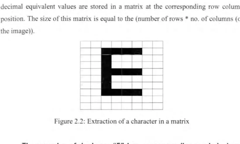
decimal equivalent values are stored in a matrix at the corresponding row column
[image:21.501.43.453.38.284.2] [image:21.501.34.462.274.651.2]position. The size of this matrix is equal to the (number ofrows
*
no. of column (of the image)).Figure 2.2: Extraction of a character in a matrix
The extraction of the image
11E"
into a corresponding
matrix is
shown
abov
e
.
Here
w
=
Numerical
v
alue
corresponding
to
white
and b
=
Numerical
v
alue corresponding
to black. From this matrix
we
find the element
which
occur
the
most.
T
his will correspond to the most prominent color, and henc
e the
background
in our
case.
This is
very
obvious as the character
will be less
prominent
than the background of
the
p
aper on
which
it has been
written or
printed.
Therefore the number of pixels constituting
the
background
will be
less
than
the number of pixels that make up the character
.
Hence our assumpt
ion is
that
the numerical
v
alues other than the background
consti
t
ute the charact
er
\\" \V \\" \\
,,
.
\\" \\" w\\" w
B
B
I
B
I
B
IW
w\Y w
B
w w \\ \\ I ". \\' wB
\\ w \\" \\" \\"w w B
B
J
B
I
B
IW
w\\" \\"
B
w w \\ \\",,
.
\\" wB
w w \\ w,,.
w w
B B
I
B
I
B
I ,,.,,
.
\\' w \Y \\" w w \\" w w w \\ \\ \\" w \\" w
8
CHAPTER III
THEORY & BACKGROUND
3.1 Chapter Overview
Some of the fundamental are reviewed in this project. First is the Malay ia
,·ehicle license plate and basic design of license plate. Then, the information of
software R2006a including its advantage will be discussed. Lastly, it's all about
eural Network Artificial, including multilayer perceptron (MLP), Neural Network
element and Neural Network architecture.
3.2 Malaysian Vehicle License Plate
Malaysian vehicle license plates are the license plates displayed on all motorized road vehicles in Malaysia. as required by law. The issue of license plates
is regulated and administered by the department. In standard regulation, all vehicle
license plates in Malaysia, other than those issued to diplomats, dealers and taxis ,
have white characters on a black background, regardless of the vehicle type. All vehicles must also display two of the same license plates numbers of the same colors
9
3.3 Basic design of license plate
The most common form of Malaysian license plates, in use smce the
introduction of motorized vehicles in the country's British colonial era, typically
begin with one or more letters (the first letter(s) serving as a vehicle or location
prefix) followed by up to four numerical digits with no leading zeros. Thus, the
configuration of a common Malaysian number plate may be in the form of ABC
1 _34. as depicted with two examples on the right. The sequence of licensed numbers
i sued begins with x 1 ("x" being the prefixes of the vehicle's registered location and
vehicle type) to x 9999, followed by xA 1 to xY 9999, xAA 1 to xAY 9999, xBA 1 to
xBY 9999, and so on (letters I, 0 and Z are not used to avoid ambiguity with numbers
or other forms of local license plates).The format is used in virtually all classes of
vehicles with engines, including, unless stated later:
• Private vehicles (cars, motorcycles, vans, trucks and other vehicles of similar
design).
• Commercial and industrial vehicles (vans, trucks - light or heavy, buses.
road-legal vehicles for construction and excavation and other vehicles of
similar design).
• Service vehicles (police cars. ambulances, fire engines, public utility vehicles
and other vehicles of similar design).
While motorcycles' rear number plates are normally displayed in standard
fashion, there is little restriction to the manner in which their license numbers are
displayed at the front, allowing them to be place on the front fender or fairing of the
vehicle. or on another license plate.
3.4 Software R2006a
Control software used for this project IS MA TLAB R2006a by The
Mathworks lnc. this software is chosen mainly because of its known capability of
modeling and simulation using Simulink and capability Image Acquisition BJockset
along with Video and Image Processing Blockset to perform visionary task for this
10
MATLAB. is used and very well known for performing mathematical
calculations, analyzing and visualizing data, and writing new software programs and
Simulink, is used for modeling and simulating complex dynamic systems such as
vehicle's automatic transmission system, advance the mapping of the human genome by developing algorithms for DNA sequencing instruments, advance the diagnosis
and treatment of gastrointestinal tract disorders by improving visual imaging of the
mall intestine and many more.
This project is run on Simulink platform with numerous user defmed
MA TLAB functions embedded to perform the desired tasks for this project. Blockset
such as Video Viewer and Image Acquisition help to capture the image from USB
cameras and stored acquired images into arrays that MA TLAB functions can
understand.
3.5 Defmition of Image Processing
The image processing is a process that takes an image as input and produces
another (modified) image as output. It focuses on image manipulation to enhance
image quality to restore an image or to compress/decompress an image. Most
algorithms on computer vision usually assume a significant amount of image
processing has taken place to improve the quality of image processing studies image
to image transformation. The input and output of image processing are both images.
Typical image processing operations include:
•:• Image compression
•:• Image restoration