i
AUTOMATIC RUBBISH COLLECTOR
MOHD YAZRI BIN ISMAIL
This report is submitted in partial fulfillment of the requirements for the award of Bachelor of Electronic Engineering (Industrial Electronics) With Honours.
Faculty of Electronic and Computer Engineering Universiti Teknikal Malaysia Melaka
ii
UNIVERSTI TEKNIKAL MALAYSIA MELAKA
FAKULTI KEJURUTERAAN ELEKTRONIK DAN KEJURUTERAAN KOMPUTER
BORANG PENGESAHAN STATUS LAPORAN
PROJEK SARJANA MUDA II
Tajuk Projek : AUTOMATIC RUBBISH COLLECTOR Sesi
Pengajian : 2009
Saya MOHD YAZRI B ISMAIL
mengaku membenarkan Laporan Projek Sarjana Muda ini disimpan di Perpustakaan dengan syarat-syarat kegunaan seperti berikut:
1. Laporan adalah hakmilik Universiti Teknikal Malaysia Melaka.
2. Perpustakaan dibenarkan membuat salinan untuk tujuan pengajian sahaja.
3. Perpustakaan dibenarkan membuat salinan laporan ini sebagai bahan pertukaran antara institusi
pengajian tinggi.
4. Sila tandakan ( √ ) :
SULIT*
(Mengandungi maklumat yang berdarjah keselamatan atau kepentingan Malaysia seperti yang termaktub di dalam AKTA RAHSIA RASMI 1972)
TERHAD* (Mengandungi maklumat terhad yang telah ditentukan oleh
organisasi/badan di mana penyelidikan dijalankan)
iii
iv
“I hereby declare that I have read this report and in my opinion this report is sufficient in terms of the scope and quality for the award of Bachelor of Electronic
v
vi
APPRECIATION
vii
ABSTRACT
viii
ABSTRAK
ix
TABLE OF CONTENTS
CHAPTER CONTENTS PAGES
TITLE OF PROJECT i
REPORT VALIDATION STATUS ii
ACKNOWLEDGEMENT iii
SUPERVISOR VALIDATION iv
DEDICATION v
APPRECIATION vi
ABSTRACT vii
ABSTRAK viii
TABLE OF CONTENTS ix
LIST OF TABLES xiii
LIST OF FIGURES xiv
LIST OF ABRIDGEMENTS xvi
LIST OF APPENDIXS xvii
I INTRODUCTION 1
1.1 Project Background 1
1.2 Problem Statement 2
1.2.1 Waste in the River and Drain 2
1.2.2 River Contamination 2
1.2.3 Continuous Process 3
1.2.4 Conventional System 3
1.2.5 Reduce Human Source 4
1.3 Objective Project 4
1.4 Scope Project 4
x
1.4.2 Design Ladder Diagram 5
1.5 Project Explanation 5
1.6 Place to Install 7
1.6.1 Drain 7
1.6.2 Water Course 7
1.6.3 River 8
II LITERATURE REVIEW 9
2.1 Type of Rubbish Collector 9
2.2 STS Band Screen 9
2.2.1 System Operation 10
2.2.2 Advantages 11
2.2.3 Disadvantages 11
2.3 Tarnos S.A – Water Screening, Filteration and Vibration System 12
2.3.1 Water Filtration Process 12
2.3.2 Self-Cleaning Screening System Description 13
2.4 Programmable Logic Controller 14
2.4.1 PLC Block Diagram 16
2.4.2 Logic Instructions (Mnemonic) 18
2.4.3 Input/Output (I/O) Assignment 18
2.4.4 Logic Instructions and Graphic Programming 18
III METHODOLOGY 21
3.1 Project Methodology 21
3.1.1 Choose the Proper Title 21
3.1.2 Propose Title to Lecturer 22
3.1.3 Analysis Project Objective 22
3.1.4 Survey Material 22
xi
3.1.6 Problem Statement 23
3.1.7 Design the Project 23
3.1.8 Hardware 24
3.1.9 PLC Ladder Diagram 24
3.1.10 PLC Programmer Tested 24
3.1.11 Troubleshooting 24
3.1.12 Final Presentation 25
3.2 Methodology Block Diagram 26
3.3 Reason to Choose This Project 27
3.3.1 Create New Product 27
3.3.2 PLC as a main Controller 27 3.3.3 Reduce River Contamination 28 3.3.4 Man Power and Healthy Protection 28 3.4 Frame Work for PSM I and PSM II 29
3.5 Block Diagram of Frame Work 30
IV RESULT AND DISCUSSION 31
4.1 Expected Result 31
4.2 Project Operation 32
4.2.1 Front Net 32
4.2.2 Container 33
4.2.3 Rear Net 33
4.2.3 Body of Project 33
4.3 Project Design 34
4.3.1 Body Construction 34
4.3.2 Container 34
4.3.3 Front Net 34
4.3.4 Rear Net 34
4.4 Automatic Operation 36
4.5 Manual Operation 38
4.6 Preliminary Result 39
xii
4.6.2 Legend of Ladder Diagram (Preliminary Result) 40
4.6.3 Mneumonic Code 42
4.7 Process and Troubleshooting 43
4.8 Process and Troubleshoot Illumination 44
4.8.1 Ladder Diagram Design 44
4.8.2 Power Window Motor 45
4.8.3 Rubbish Collector System 46
4.9 Actual Result 47
4.9.1 Ladder Diagram Process 47
4.9.2 Mneumonic Code 48
4.9.3 Legend of Ladder Diagram 49
4.9.4 Grafcet 51
4.10 Installation And Construction 53
4.10.1 Body Installation 53
4.10.2 Front Net 54
4.10.3 Main Container 55
4.10.4 Rear Net 55
4.10.5 Top Cover 56
4.11 Safety Precaution 57
4.12 Project Analysis 58
4.12.1 Power Window Analysis 58
4.13 Discussions 61
V CONCLUSION AND SUGGESTION 63
5.1 Conclusion 63
5.2 Suggestion 64
REFERENCES 65
xiii
LIST OF TABLES
NO TITLE PAGES
2.1 Differentials between PLC and PIC 15
2.2 Differentials between PLC and Conventional Controller 16
2.3 Mnemonic Code 18
2.4 Basic Instructions 19
xiv
LIST OF FIGURES
NO TITLE PAGES
1.1 Conventional System 3
1.2 Rubbish Collector Machine 3
1.3 Drain 7
1.4 Water Course 8
1.5 River 8
2.1 STS Band Screen 10
2.2 Operation System of STS Band Screen 10
2.3 Real condition of STS Band Screen 11
2.4 TARNOS S.A System 13
2.5 Process Operation of TARNOS’ S.A 13
2.6 Single PLC controlling a single or some output service 14
2.7 PLC Block Diagram 16
3.1 Methodology Block Diagram 26
3.2 Planning Progress 29
3.3 Frame Work 30
4.1 Interface between Hardware and Software 31
4.2 Project Operation 32
4.3 Body Construction 35
4.4 Container 35
4.5 Front Net 35
4.6 Rear Net 35
4.7 Automatic Operation Flow 36
4.8 Manual Operation Flow 38
xv
4.10 Mneumonic Code 42
4.11 Process and Troubleshoot 43
4.12 Programmable Logic Controller 44
4.13 Power Window Motor 45
4.14 Ladder Diagram 47
4.15 Mneumonic Code 48
4.16 Grafcet 51
4.17 Side View 53
4.18 Top View 53
4.19 Front Net 54
4.20 Main Container 55
4.21 Rear Net 55
xvi
LIST OF ABRIDGEMENTS
PLC - Programmable Logic Controller ARC - Automatic Rubbish Collector DC - Direct Current
xvii
LIST OF APPENDIXS
NO TITLE PAGE
1
CHAPTER 1
INTRODUCTION
1.1 PROJECT BACKGROUND
Malaysia is a one of country in the world have a beautiful river. But at this time the condition of river in Malaysia very bad with behavior of Malaysian people like to throw the domestic waste into the river. This action can make flood occurred and make many people nearest the river suffer.
Malaysia government invest every year to make sure the condition of the river at the good condition. Many program from Ministry of Agriculture did to launch to give more expose about deterioration of habit like to throw the domestic waste into the river. Beside that, government also invest many money to build the rubbish trap but this solution not give the big impact to make sure the river clean from the waste. The best solution is come from Malaysian people about importance to protect the river.
2
occurred at Klang river and we are also hear about flood destroyed the residence and asset. This problem need the solution to ensure Klang river absolve from the waste problem.
One of the solution is design the waste trap to collect the rubbish to follow the schedule or time set. From this problem, Automatic Rubbish Collector will be design to solve this problem.
1.2 PROBLEM STATEMENT
Have a several problem identify before to create Automatic Rubbish Collector. The problem occur is like waste in the river and drain, river contamination, continuous process, conventional system and reduce human power.
1.2.1 Waste In The River And Drain
This problem can occurred when the people throw the rubbish into drain or river. This action can induce the flood and can create the smelly environment. Beside that, mosquito problem also can happen and this give the danger environment to people.
1.2.2 River Contamination
3
1.2.3 Continuous Process
Waste in the river need the continuous process to make sure the river free from contamination. This process can be continuous if all the system change to programming system. Either programming system can use to make the system control automatically is Programmable Logic Controller (PLC). All system will be control by a timer and all process can set follow by system requirement.
1.2.4 Conventional System
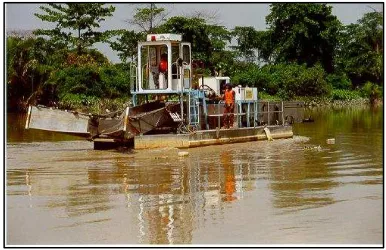
[image:20.595.212.402.429.536.2]At Malaysia, the system to use to collect or manage the waste still use the conventional system. For example, at Klang River net will be use to block the domestic waste but at the same time process to collect the waste shall use manual system. Manual system mean is still use the worker from human to collect the rubbish or waste. Figure 1.1 is show how the conventional system operated used the net system. For figure 1.2 show one of rubbish collector machine used at handle by human to operate.
Figure 1.1 Conventional System. Use net to block rubbish
[image:20.595.210.403.589.714.2]4
1.2.5 Reduce Human Source
Work with waste environment can expose the human to bad side effect. In the sophisticated area and to achieve advance country now time to make sure any work or job where can give the bad side effect to people will be complete by machine or robot.
1.3 OBJECTIVE PROJECT
The main project objective to build this system is :
i. To design and build one equipment to collect automatically rubbish in the river.
ü Ensure the rubbish collector system at Malaysia can use in automatically system without destroy the ecosystem.
ii. To design one systematic process in collecting rubbish field and to make sure process will be continuous without monitoring by supervisor.
ü Ensure the process system will do at everyday or follow the setting time without any monitoring from supervisor. This system can ensure the collecting process will follow the schedule.
iii. To learn about PLC program include Ladder Diagram of PLC.
ü Practice what which study in the class to real environment and to familiarize the student with work environment.
iv. To comprehend of PLC wiring diagram and real wiring of PLC between hardware.
v. To reduce the river contamination and to raise the quality water.
1.4 SCOPE PROJECT
5
the auto collector rubbish and how this project function. Auto collector rubbish will used the PLC as a main brain to control all system.
1.4.1 Produce The Prototype
This project to build mini prototype of the Automatic Rubbish Collector Using PLC System. Size of project very minimized if compare with the real size. Size of real project also depend from size of river or drain to install. This project very flexible and can do the upgrade process to give high performance.
Installation The Programmable Logic Controller (PLC)
Programmable logic controller or PLC is a main controller for this project. All process will be control by PLC ladder diagram and any change of the process can repair at ladder diagram. Ladder diagram instruction will be install or kept in PLC memory to run the process. From ladder diagram also, any problem occurred can be detect and shall to repair.
1.4.2 Design Ladder Diagram
Design the ladder diagram follow from process type to ensure the system operate in every steps. If have mistake at ladder diagram will be stir up in mistake at operation of project.
1.5 PROJECT EXPLANATION
Automatic Rubbish Collector Using PLC Systems is a one system to collect the rubbish or waste in the river and drain automatically. Main objective to design this project is to ensure the collecting process operation in consecutive condition.
6
diagram, all sequence of the project step will be show. That is make easier to troubleshooting the problem.
Another components used to build this system is power window motor. Power window motor is a DC motor and need the small supply to operate. Beside that, price of each power window motor very cheap make that motor is selected to use for this project. In this project, power window motor will move in two condition where for the first condition is at forward and at the second condition is at reverse condition. Polarity of supply to power window motor will be change for reverse condition.
7
1.6 PLACE TO INSTALL
After make the research, have a several place suitable to install Automatic Rubbish Collector. Another top place can be install this system is drain, water course and river.
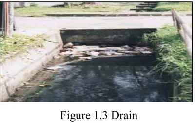
1.6.1 Drain
This project can be installed at the small or large drain. This concept for all of concept still be same. Figure 1.3 is shown the example of drain can be install this system. Time to collect the rubbish and waste can be set follow the supervisor.
Merely for design at drain, more safety needed to avoid the system and also to avoid the human from danger.
1.6.2 Water Course
Water course use to supply the water into the paddy field. Water want to supply must be don’t have any rubbish or waste.
[image:24.595.230.430.331.457.2]This waste sometime can give the bad effect to the growth of paddy. Figure 1.4 can shown the type of water course where the system can be install to trapped the rubbish.