radial-axial ring rolling.
White Rose Research Online URL for this paper: http://eprints.whiterose.ac.uk/106305/
Version: Accepted Version
Article:
Hua, L., Deng, J., Qian, D. et al. (2 more authors) (2016) Modeling and application of ring stiffness condition for radial-axial ring rolling. International Journal of Machine Tools and Manufacture, 110. pp. 66-79. ISSN 0890-6955
https://doi.org/10.1016/j.ijmachtools.2016.09.003
Article available under the terms of the CC-BY-NC-ND licence (https://creativecommons.org/licenses/by-nc-nd/4.0/)
[email protected] https://eprints.whiterose.ac.uk/
Reuse
This article is distributed under the terms of the Creative Commons Attribution-NonCommercial-NoDerivs (CC BY-NC-ND) licence. This licence only allows you to download this work and share it with others as long as you credit the authors, but you can’t change the article in any way or use it commercially. More
information and the full terms of the licence here: https://creativecommons.org/licenses/
Takedown
If you consider content in White Rose Research Online to be in breach of UK law, please notify us by
http://dx.doi.org/10.1016/j.ijmachtools.2016.09.003
International Journal of Machine Tools & Manufacture, Vol. 110 (2016), pp. 66-79
http://dx.doi.org/10.1016/j.ijmachtools.2016.09.003
Modeling and application of ring stiffness condition for radial-axial ring rolling
Lin Huaa, c, Jiadong Denga, c, Dongsheng Qianb, c*, Jian Lana, c, Hui Longd
a School of Automotive Engineering, Wuhan University of Technology, Wuhan 430070, China
b School of Materials Science and Engineering, Wuhan University of Technology, Wuhan 430070, China c Hubei Key Laboratory of Advanced Technology for Automotive Components, Wuhan 430070, China d Department of Mechanical Engineering, The University of Sheffield, Sheffield S1 3JD, UK
* Corresponding author at: Wuhan University of Technology, Wuhan 430070, China. E-mail address: [email protected] (D. Qian).
Abstract
Radial-axial ring rolling (RARR) is an advanced rotary forming technology for manufacturing
various seamless rings, especially for large scale rings. A primary problem for RARR is to
facilitate rolling process stability and form a ring with good dimension and performance.
However, RARR is an extremely complex dynamic rolling process with high flexibility. To
reasonably control guide roll is an important approach to keep rolling process stable during
RARR. In this paper, a mathematical model of ring stiffness condition for RARR was established
based on the force method. Then the influence factors to ring stiffness were discussed,
especially the section bending moment factor. To verify the ring stiffness model, finite element
(FE) simulation was adopted. In addition, a comparison of different ring stiffness models was
made. It can be found the proposed stiffness model has a high accuracy. Furthermore, a control
method of the pressure in the hydraulic cylinder to adjust the guiding force based on the
stiffness model was proposed. By FE simulation of RARR, an appropriate adjustment coefficient
todetermine the guiding force was obtained. Finally, an experiment of RARR for a large ring
was carried out. The rolling process was very smooth and steady, and a super-large ring with
diameter more than 9 meters was manufactured successfully.
Keywords: Radial-axial ring rolling; Guide roll; Ring stiffness condition; Mathematical
1 Introduction
Ring rolling is an advanced rotary forming technology to manufacture seamless rings, such as
bearing races, ring gears, flanges, aero-engine casings, etc. Compared with traditional
manufacturing technologies, it has advantages of high producing efficiency and processing
precision, low energy consumption and material cost, good microstructure and performance. Over
160 years, ring rolling has evolved into a relatively mature technology [1, 2], with amount of
research work in theory [3-6], technique [7-10] and equipment [11, 12].
As a typical ring rolling method, RARR is suited to manufacture large scale rings at high
temperature. During RARR, as shown in Fig. 1, the thickness of a ring is reduced by the radial
extrusion of the main roll and mandrel, and the height is reduced by the axial extrusion of the upper
and lower conical rolls. In radial deformation area, the main roll makes active rotary motion and the
mandrel makes radial feed movement. In axial deformation area, the upper conical roll makes
downward feed movement and the two conical rolls both make active rotary motion. When the
thickness and height of the ring reduce, the diameter of the ring enlarges. The two conical roll also
move backwards to keep them contact with the ring surface during rolling process. The two guide
rolls are arranged respectively in the two sides of the main roll to steer the ring and keep the rolling
[image:3.595.156.439.594.753.2]process stable.
http://dx.doi.org/10.1016/j.ijmachtools.2016.09.003
From the forming principle of RARR above, it can be seen that RARR is an extremely
complex dynamic rolling process with high flexibility. Recently, researches on RARR are mainly
focused on FE modeling method and process simulation. For instance, Xie et.al [13] developed a rigid–viscoplastic dynamic explicit finite element code to simulate ring rolling. Davey and Ward
[14] proposed a practical method for FE simulation of RARR using ALE flow formulation instead
of conventional Lagrangian approach. Kim et al. [15] put forward a dua-mesh approach to RARR
simulation with high computational efficiency. Simulations of microstructure evolution during
RARR have been also tried [16-18]. By FE simulation, deformation behaviors during RARR and
effects of technological parameters on RARR process have been revealed systematically [19-23]. Besides, macro–microscopic deformation laws during blank forging and ring rolling process have
been investigated [24].
To facilitate rolling process stable and form a ring with good dimension and performance,
some rolling conditions have been proposed. To make the ring rotate smoothly, biting condition in
radial and axial rolls should be satisfied [25]. To make the ring produce plastic deformation, the
penetrating condition in radial and axial deformation areas should be met [25]. Furthermore, to
make rolling process stable, a steady forming condition for RARR should be guaranteed [26]. In the
process of real manufacturing, waste ring product with distorted shape is an important problem, as
[image:4.595.171.426.647.760.2]shown in Fig. 2. One key reason is that the force applied on the guide roll is inappropriate.
At present, some scholars have made studies on the guide roll of ring rolling. Hua et al. [27]
adopted a theoretical method to predict the motion rule of guide roll by calculating the ring size
during cold radial ring rolling process of a groove ball ring. Li et al. [28] proposed a method to
control the guide rolls by adjusting the pressure of hydraulic mechanism in 3D-FE radial ring
rolling simulation. Xu et al. [29] put forward a plastic instability criterion for radial ring rolling and
calculated the bending moment of ring under the action of guide rolls by the force method.
Forouzan et al. [30] put forward employing thermal spokes method to simulate the guide roll effect
in FE analysis of radial ring rolling process. However, compared with radial ring rolling, the rolling
system of RARR is more complex. A pair of conical rolls is involved in the deformation and formed
rings are in big size. Therefore, it is more important for RARR to control the guide rolls. Xu et al.
[31] adopted the limit analysis method to establish the relationship between the allowed maximum
force and the angle of the guide roll, and pointed out the most suitable angle of the guide roll. Hua
et al. [32] proposed a ring stiffness condition for RARR, but it made a simplification to calculate the
bending moment and emphasized on the permitting maximum outer radius of a ring. However, the
research emphases above were not on how to control the force of guide roll based on the guide roll
system of RARR.
This study aims to provide a scientific theoretical basis and reliable control method of guide
roll during RARR. Firstly, a mathematical model of ring stiffness condition for RARR was
established based on the force method. Then the influence factors to ring stiffness were discussed
and the predicted results were compared with FE simulation and other ring stiffness models. Finally,
a control method of the pressure in the hydraulic cylinder to adjust the guiding force based on the
http://dx.doi.org/10.1016/j.ijmachtools.2016.09.003
2 Mathematical modeling of ring stiffness condition for RARR
2.1 Establishment of the ring stiffness model
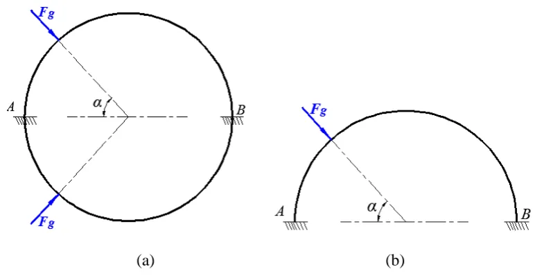
During RARR, the ring is deformed under the pressure of the main roll and mandrel in the
radial direction and the pressure of the two conical rolls in the axial direction. Assuming the
rotational motions are ignored, the mechanical model for RARR can be regarded as a circular beam
with rectangular section fixed in the radial deformation area A and axial deformation area B, as
shown inFig. 3(a). The pressure of the guide roll applied on the ring is simplified as a concentrated
force Fg pointing to the center of the circle. To simplify the model, the forces of the two guide rolls
are supposed to be equal and the cross-sections of the rolled ring are supposed to be unified. Thus, it
is a symmetric model, and a half model can be used to analyze themechanical condition, as shown
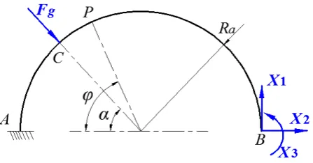
in Fig. 3(b). It is a three times statically indeterminate structure. Generally, the force method and
displacement method are two basic and effective means to calculate statically indeterminate
structures. In this paper, the force method is selected to analyze the mechanical condition. Based on
the force method, the fixed joint at section B is removed and equivalent support reaction is added,
as shown in Fig .4. X1, X2 are the support forces in horizontal and vertical directions respectively,
and M3 is the support moment.
[image:6.595.102.490.556.755.2]
(a) (b)
Fig. 4. Equivalent mechanical model based on the force method
Firstly, the section bending moment of the circular beam caused by each force should be
obtained. The section bending moment of the circular beam Mg
caused by the guiding forceFg can be defined as
0sin( )
g
g a
M
F R
( 0 )
( ) (1)
where Ra is the average diameter of the rolled ring, the section P is an any section on the beam and
is the central angle of the arc »AP, is the position angle of guide roll.
Then the section bending moment of the circular beam M1
caused by the unit load X1in the same direction as X1 can be expressed as
1 a(1 cos ) 0
M R (2)
The section bending moment of the circular beam M2
caused by the unit load X in the 2same direction as X2 can be expressed as
2 asin 0
M R (3)
The section bending moment of the circular beam M3
caused by the unit load X in the 3same direction as X3 can be expressed as
3 1 0
M (4)
Then the generalized displacement caused by each force at section B should be calculated. The
generalized displacement 1g caused by Fg at the section B in the same direction as X1 can be
http://dx.doi.org/10.1016/j.ijmachtools.2016.09.003
31
0
1 1
[ cos (cos 2 1) sin sin 2
4 4
1
sin 1 cos ] 2
g g a
g a
M M F R
R d EI EI
1 (5)where E is the elastic modulus, I is the inertia moment.
The generalized displacement 2g caused by Fg at the section B in the same direction as X2
can be calculated by
32
0
1 1 1
[ sin (cos 2 1) cos sin 2 cos ]
4 4 2
g g a
g a
M M F R
R d
EI EI
2
(6)The generalized displacement 3g caused by Fg at the section B in the same direction as X3
can be calculated by
33 3
0 (cos 1)
g g a
g a
M M F R
R d
EI EI
(7)The generalized displacement 11 caused by X1 at the section B in the same direction as X1
can be calculated by
31 1 11 0 2 3 a a
M M R
R d
EI EI
(8)The generalized displacement 22 caused by X at the section B in the same direction as X2 2
can be calculated by
32 2
22
0 2
a a
M M R
R d
EI EI
(9)The generalized displacement 33 caused by X at the section B in the same direction as X3 3
can be calculated by
3 3
33 0
a a
M M R
R d
EI EI
(10)The generalized displacement 12 caused by X at the section B in the same direction as X2 1
is equal to the generalized displacement 21 caused by X1 at the section B in the same direction
as X2, and can be calculated by
31 2
12 21 0
2 a
a
M M R
R d
EI EI
The generalized displacement 13 caused by X at the section B in the same direction as X3 1
is equal to the generalized displacement 31 caused by X1 at the section B in the same direction
as X3, and can be calculated by
21 3
13 31 0
a a
M M R
R d
EI EI
(12)The generalized displacement 23 caused by X at the section B in the same direction as X3 2
is equal to the generalized displacement 32 caused by X at the section B in the same direction 2
as X3, and can be calculated by
22 3
23 32 0
2 a
a
M M R
R d
EI EI
(13)Based on the force method, the regular equation of this three times statically indeterminate
structure can be expressed as
11 1 12 2 13 3 1
21 1 22 2 23 3 2 31 1 32 2 33 3 3
+ + + =0
+ + + =0
+ + + =0
g
g g
X X X
X X X
X X X
(14)
Then the equivalent support reaction at section B can be obtained
1
1
sin
g
X F
(15)
2 2 2 2
2
1 2
[ sin ( cos cos
2 8 8 8
2 1
sin sin ) (cos 1)] 8
g a g a
a
g a
X F R F R
R F R (16)
3 2 2 2 2
2 2 1
( cos cos sin sin )
8 8 8 8
g a
X F R
(17)
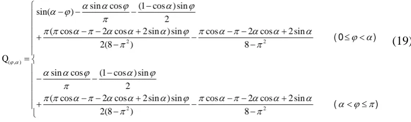
Finally, the section bending moment of the circular beam at section P can be calculated by
( ) g a ( , )
M F R Q (18)
http://dx.doi.org/10.1016/j.ijmachtools.2016.09.003
2 2
( , )
2 2
sin cos (1 cos ) sin sin( )
2
( cos 2 cos 2 sin ) sin cos 2 cos 2 sin
2(8 ) 8
sin cos (1 cos ) sin 2
( cos 2 cos 2 sin ) sin cos 2 cos 2 sin
2(8 ) 8
Q
( 0 )
( ) (19)
Then the section bending stress can be calculated by the following formula
( ) ( , )
2
6 a g
z
M R F Q
W BH
(20)
To satisfy the stiffness condition, the maximum section bending stress should satisfy the
following expression
( )max ( , )max
max 2 6 [ ] a g s z
M R F Q
W BH
(21)
Thus, to avoid distorting the ring shape, the guiding force should satisfy the stiffness condition
2
( , ) max
6 s g g a BH F F
R Q
max (22)
2.2 Discussion of the ring stiffness model
According to Eq. (22), the ring stiffness condition in RARR is related to its geometric
dimension and yield strength, and also has relation with the maximal absolute valve of the section
bending moment factor
( , ) max
Q . Bigger geometric dimension of ring cross section, smaller
geometric dimension of ring radius and bigger yield strength of ring material can make the ring to
bear bigger force before being distorted, which are good for improving the ring stiffness. As we can
see from Eq. (19), the expression of the section bending moment factor Q( , ) is related to the
position angle of guide roll and the angle of ring section position , but the detail is not clear.
[image:10.595.134.537.58.178.2]Therefore, a further study on the section bending moment factor Q( , ) is made in this section. The
along the ring section changes from state I to state II when increases. That is to say, when is
smaller than a certain valve, the distribution state of Q( , ) likes an inverted letter N. The maximal
absolute valve of the section bending moment factor
( , ) max
Q may only occur in section A,
section B, section C or section D. Section A is between the main roll and mandrel in the ring. The
absolute valve of the section bending moment factor at section A can be expressed as
( ,0) 2
sin cos 2 cos 2sin
= sin
8
Q
(23)
Section B is between the two conical rolls in the ring. The absolute valve of the section
bending moment factor at section B can be calculated by
( , ) 2
sin cos 2 cos 2sin
8
Q
(24)
Section C is contacted with the guide roll in the ring. The absolute valve of the section bending
moment factor at section C can be determined by
2
( , )
2
sin cos (1 cos ) sin ( cos 2 cos 2 sin ) sin
2 2(8 )
=
cos 2 cos 2 sin 8
Q
(25)
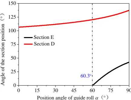
Section D is between section C and B. A peak valve of Q( , ) occurs at this section. When is
bigger than a certain valve, the distribution state of Q( , ) likes an inverted letter W. In this case,
another peak valve of Q( , ) occurs at section E which is between section A and C. The derivatives
of Q( , ) with respect to at section D and E are both equal to 0.
Then the derivative of Q( , ) with respect to can be calculated by the following expression
2
( , )
2
sin sin (1 cos ) cos ( cos 2 cos 2sin ) cos cos( )
2 2(8 )
sin sin (1 cos ) cos ( cos 2 cos 2sin ) cos
2 2(8 )
Q
( 0 )
( )
(26)
When Q( , ) =0
http://dx.doi.org/10.1016/j.ijmachtools.2016.09.003
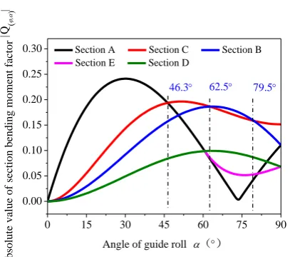
shown in Fig .6. The certain valve of is about 60.3º. Then the value of Q( , ) at section A, B, C,
D and E for different can be calculated, as shown in Fig .7. The maximal valve of Q( , ) for
different can be only at section A, B or C. When 0 46.3, the maximal valve of Q( , ) is
at section A. When 46.3 62.5 or 79.5 90 , the maximal valve of Q( , ) is at
section C. When 62.5 79.5, the maximal valve of Q( , ) is at section B. The derivative of
( , )
Q with respect to at section A, B, C, D and E for different can be calculated
0 20 40 60 80 100 120 140 160 180
-0.2 -0.1 0.0 0.1 0.2 0.3 0.4
State II
S
ec
ti
on be
nding m
ome
nt fa
ctor
Q (
Angle of the section position ° State I
[image:12.595.194.405.250.412.2]Fig. 5. Relationship between , and Q( , ).
0 15 30 45 60 75 90
0 25 50 75 100 125 150
Angle
of
the se
cti
on posit
ion
°
Position angle of guide roll ° Section E
Section D
60.3
Fig. 6. Position of section E and D under different
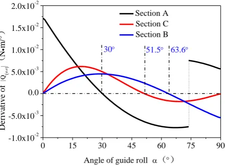
The derivative of Q( , ) with respect to at section A, B and C can be calculated, as shown
in Fig .8. As it can be seen, the maximal valve of Q( , ) at section A occurs when =30. For
section B, the maximal valve occurs when =63.6. And for section C, the maximal valve occurs
[image:12.595.189.406.449.615.2]( , ) max
Q for different can be calculated, as shown in Fig .9. It can be seen the valve of
( , ) max
Q depends on the position angle of guide roll . The maximal valve of
( , ) max
Q occurs
when =30 . When 0 30 , 46.3 51.5 or 62.5 63.6 , the valve of
( , ) max
Q increases with position angle of guide roll. And when 30 46.3 ,
51.5 62.5 or 63.6 90 , the valve of
( , ) max
Q decreases with position angle of
guide roll. Therefore, the influence of
( , ) max
Q to the ring stiffness can be come down to the
position angle of guide roll . As we can see, the position angle of guide roll has a complex
influence to the ring stiffness. When the position angle of guide roll is smaller than 30º, the ring
stiffness is weakened as increasing. And when is bigger than 30º, the ring stiffness can be
improved generally as increasing. However, the ring stiffness is weakened when
46.3 51.5 or 62.5 63.6.
0 15 30 45 60 75 90
0.00 0.05 0.10 0.15 0.20 0.25 0.30
Absolut
e va
lue of
sec
ti
on be
nding m
om
ent fa
ctor
|Q
(
Angle of guide roll °
Section A Section C Section B Section E Section D
79.5
62.5
[image:13.595.200.404.397.577.2]46.3
http://dx.doi.org/10.1016/j.ijmachtools.2016.09.003
0 15 30 45 60 75 90
-1.0x10⁻² -5.0x10⁻³ 0.0 5.0x10⁻³ 1.0x10⁻² 1.5x10⁻² 2.0x10⁻² Deriva ti ve of |Q ( N m / °
[image:14.595.138.482.48.474.2]Angle of guide roll ° Section A Section C Section B 63.6 51.5 30
Fig. 8. Derivative of Q( , ) under different for section A, B and C
0 15 30 45 60 75 90
0.00 0.05 0.10 0.15 0.20 0.25 0.30 Ma xim um a bsolut e va lve of se nc ti on be nding m ome nt fac tor |Q ( )
|max
Angle of guide roll ° 79.5 62.5 46.3 63.6 51.5 30
Fig. 9. Values of
( , ) max
Q under different
2.3 Verification by FE simulation
To verify the result above, a static FE simulation for a half circular beam is made in ABAQUS.
The all degrees of freedom at the two ends of the half circular beam A and B are limited. The load
applied by guide roll to ring is on section C with two component forces Fx and Fy respectively in
direction x and y, as shown in Fig. 10(a). The valve of the resultant force of Fx and Fy is equal to the
guide force Fg and the direction is pointed to the center of the circle. A rectangular profile is
selected for the beam,as shown in Fig. 10(b). The yield strength of the ring material is 40 MPa. The
elastic modulus is 116.7449GPa. And the poisson ratio is 0.3. The element type is selected as beam
[image:14.595.187.413.60.227.2](a) (b)
Fig. 10. A static FE model for a half circular beam: (a) FE model; (b) section shape.
When the average radius of the circular beam Ra=4.596 m, the length of the profile a=0.308 m
and the width b=0.308 m, the angle of the guiding force =22.66 º, the resultant force of Fx and Fy
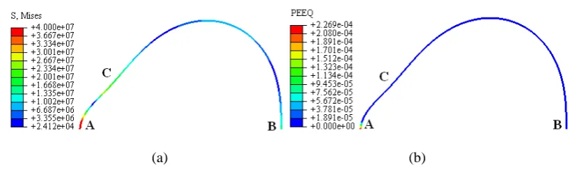
is equal to 2.5×10⁵ N, the simulation results are shown in Fig. 11. It can be seen the beam produced
plastic bending deformation which meant the stiffness of the beam is destroyed. The maximum
stress and strain occur at section A. So a further study about the relationship between the guiding
force and the deformation performance at section A is made, as shown in Fig. 12. When the guiding
force increases to 1.85×10⁵ N, the Mises stress at section A reaches the yield strength and the
material begins to produce plastic bending deformation. According to Eq. (22), the maximum
allowed guiding force Fg-max can be calculated, the valve is 1.853×10⁵ N. Thus it indicates the
proposed stiffness model can predict the maximum allowed guiding force accurately.
(a) (b)
[image:15.595.90.506.568.693.2]http://dx.doi.org/10.1016/j.ijmachtools.2016.09.003
0.0 5.0x10⁴
1.0x1051.5x105 2.0x10⁵ 2.5x10⁵ 0
1x10⁷ 2x10⁷ 3x10⁷
4x10⁷ Mises stress
PEEQ
Guiding force N
Mises
stress
(
Pa)
1.85x10⁵
-5.0x10⁻⁵ 0.0 5.0x10⁻⁵ 1.0x10⁻⁴ 1.5x10⁻⁴ 2.0x10⁻⁴ 2.5x10⁻⁴
PEE
[image:16.595.176.422.65.225.2]Q
Fig. 12. Evolution of Mises stress and equivalent plastic strain under different guiding force.
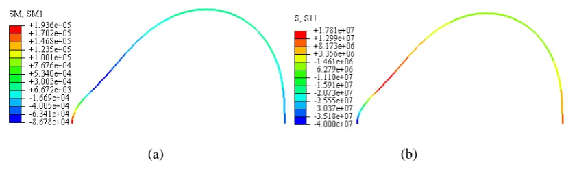
Based on the FE model above, when the resultant force of Fx and Fy is equal to 1.85×10⁵ N, it
is a critical state to produce plastic instability. The simulative results of section bending moment
and stress are shown in Fig. 13. According to Eqs. (18) and (20), the theoretical results of section
bending moment and stress can be calculated. Fig. 14 shows a comparison of simulative and
theoretical results of section bending moment and stress. It can be found the results have a good
agreement.
(a) (b)
Fig. 13. Simulative results of section bending moment and stress: (a) section bending moment; (b)
[image:16.595.91.503.475.600.2]0 20 40 60 80 100 120 140 160 180 -1.0x10⁵
-5.0x10⁴ 0.0 5.0x10⁴ 1.0x10⁵ 1.5x10⁵ 2.0x10⁵ 2.5x10⁵
S
ec
ti
on be
nding m
om
ent
N
m
Angle of section position ° Simulative value Theoretical value
0 20 40 60 80 100 120 140 160 180
-5x10⁷ -4x10⁷ -3x10⁷ -2x10⁷ -1x10⁷ 0 1x10⁷ 2x10⁷
S
ec
ti
on be
ndin
g st
re
ss (P
a)
Angle of section position Simulative value Theoretical value
[image:17.595.92.515.55.241.2](a) (b)
Fig. 14. Comparison of simulative and theoretical results of section bending moment and stress: (a)
section bending moment; (b) section bending stress.
According to Eq. (21), the maximum section bending stress for a ring with certain size and material mainly depends on
( , ) max
Q . According to Fig. 7, it can be seen the maximum valve of
( , )
Q occurs at different position when the position angle of guide roll changes. Thus, to make
the beam produce plastic deformation under different angles of guiding force is tried. The
simulative result is shown in Fig. 15. As it can be seen when = {22.66 º, 50 º, 70 º, 90 º}, the
earliest position to produce plastic deformation is respectively at section A, section C, section B,
section C. And from Fig. 7, the following law can be found. When 0 46.3, the maximal
valve of Q( , ) is at section A. When 46.3 62.5 or 79.5 90 , the maximal valve
of Q( , ) is at section C. When 62.5 79.5, the maximal valve of Q( , ) is at section B.
Thus, this law can explain the phenomenon appearing in Fig. 15.
(a) (b)
A B
C
A B
http://dx.doi.org/10.1016/j.ijmachtools.2016.09.003
[image:18.595.66.476.58.177.2](c) (d)
Fig. 15. The earliest position to produce plastic deformation: (a) =22.66 º, Fg=1.85×10⁵ N; (b)
=50 º, Fg=2.2×10⁵ N; (c) =70 º, Fg=2.4×10⁵ N; (d) =90 º, Fg=2.9×10⁵ N.
2.4 Comparison of different ring stiffness models
Recently, scholars have proposed some stiffness models for RARR. In this section, a
comparison between some typical models and our model is made.
The stiffness model proposed by Xu et al. (X-model) [31] can be described as the following
formula
2
max X( )
s g Xg
a
BH
F F K
R
(27)
where FXg-max is the maximum allowed guiding force based on X-model, the coefficient
2
X( )
1 sin
1 2
1 sin 1
2sin 2 cos
2 K
.
The stiffness model proposed by Hua et al. (H-model) [32] can be described as the following
formula
2
max ( )
s
g Hg H
a
BH
F F K
R
(28)
where FHg-max is the maximum allowed guiding force based on H-model, the coefficient
( )
1 6 sin
H
K
.
To make an easy comparison, the stiffness model proposed by us (D-model) can be also
described as the following formula
A B
C
A B
2
max ( )
s
g Dg D
a
BH
F F K
R
(29)
where FDg-max is the maximum allowed guiding force based on D-model, the coefficient
( )
( , ) max
1
6
D
K
Q
.
As it can be seen, the forms of the stiffness models above are similar. The difference is in the
coefficient K( ), which is a function of . When increases from 0 º to 180 º, the coefficient K( ) for
the three models can be calculated, as shown in Fig. 16. It shows that all the valves of coefficient
K( ) have a fast decrease when is smaller than 15 º, and then become a steady level. Besides, the
valve of KD( ) is between the valves of KX( ) and KH( ).
0 15 30 45 60 75 90
0 5 10 15 20 25 30
Va
lve of
the c
oe
ff
icie
nt
K
(
)
Angel of guide roll ° KD()
KX() KH()
20 30 40 50 60 70 0.0
[image:19.595.182.409.336.507.2]0.5 1.0 1.5 2.0 2.5
Fig. 16. Comparison of the coefficient K( ) for the three models.
To make a further comparison of the predicted accuracy of the three models above, the
maximum allowed guiding force based on the three models can be calculated, according to Eqs.
(27), (28) and (29). The angle of guide roll and the geometry size of the ring are two important
factors to the maximum allowed guiding force. So the maximum allowed guiding force under
different angles of guide roll and geometry sizes of a ring during rolling process for the three
models are analyzed. Furthermore, corresponding FE simulations based on Section 2.3 are made. To
make an easy comparison of the predicted accuracy of the three models, the ratios of the theoretical
http://dx.doi.org/10.1016/j.ijmachtools.2016.09.003
indicates the results of D-model have a good agreement with the simulative results. The results of
X-model are bigger than the simulative results and the results of H-model are smaller than the
simulative results. In addition, the angel of guide roll has a little influence to the accuracy for
D-model, but an obvious influence for X-model and P-model. A larger ring size has a better
accuracy for D-model and H-model, but a worse accuracy for X-model.
15 30 45 60 75 90
0.0 0.5 1.0 1.5 2.0 2.5 3.0
R
ati
o of
theo
re
ti
ca
l t
o sim
ulative
va
lve
Angel of guide roll ° D-model X-model H-model
1.5 2.0 2.5 3.0 3.5 4.0 4.5
0.0 0.5 1.0 1.5 2.0 2.5 3.0
R
ati
o of the
ore
ti
ca
l t
o si
m
ulati
ve
va
lve
Middle radius of a ring Ra m D-model X-model H-model
[image:20.595.61.466.220.412.2](a) (b)
Fig. 17. Comparison of the predicted accuracy of the maximum allowed guiding force for the three
models: (a) under different angles of guide roll; (b) under different radiuses of a ring.
3 Application of ring stiffness model for RARR
3.1 Theoretical analysis
For RARR mill, the movement of guide roll is controlled by the hydraulic cylinder. When the
length of the hydraulic cylinder is extended or shortened, the guide roll installed on the swing arm
can swing forward or backward around the hinge D, as shown in Fig. 18. The force of guide roll Fg
applied on the ring is controlled by adjusting the pressure p in the hydraulic cylinder. Therefore, it is
Fig. 18. Mechanical structure of guide roll system in radial-axial ring rolling mill
Fig. 19. A simplified structure diagram of guide roll system during ring rolling .
In order to facilitate the analysis, a simplified structure model is adopted, as shown in Fig. 19.
To satisfy the mechanical equilibrium condition, the following equation should be ensured
1sin sin
p g
F L F L (30)
where Fp is the force of hydraulic cylinder, L1 is the length of beam JD, L is the length of beam DG,
is the supplementary angel of DGO1, is the angel of DJE.
According to the geometrical relationship, the valves of and can be calculated by the
following formulas
2 2 2 2
( ) ( )
arccos
2 ( )
g m D D
g
L R R R R x y
L R R
(31)
2 2 2 2 2
1 1 1
2 2
1 1 1
( sin ) ( cos ) ( ) ( )
arccos
2 ( sin ) ( cos )
D D E D D E D E D E
D D E D D E
L x L x y L y x x y y
L x L x y L y
(32)
where Rg is the radius of the guide roll, R is the outer radius of the ring, Rm is the radius of the main
roll, xD and yD are the coordinate of hinge D in direction x and y respectively, xE and yE are the
http://dx.doi.org/10.1016/j.ijmachtools.2016.09.003
2 2 2 2 2 2 2
1 2
2 2
1
( ) ( )
arctan arccos arccos
2
2 ( )
D m D g
m D
D
D D m D
y R R x L R R
R R x L L L
y L y R R x LL
(33)
where L2 is the length of beam JG.
Finally, the pressure p in the hydraulic cylinder can be expressed as
2 1 sin sin g h F L p r L
(34)
where rh is the inner radius of the hydraulic cylinder.
Therefore, if the suitable force of guide roll Fg applied on the ring can be determined, the
pressure p in the hydraulic cylinder can be also determined. From the analysis above, it can be seen
the maximum allowed guiding force Fg-max is determined by Eq. (22). So the pressure p should
satisfy the following condition
2
max 2
( , )max 1
sin 6 sin s a h BH L p p
R Q r L
(35)
Thus, during RARR, the pressure p can be set as
2
max 2
( , )max 1
sin
6 sin
g s
g
a h
k BH L p k p
R Q r L
(36)
where kg is an adjustment coefficient and 0kg 1.
Therefore, the force applied on the guide roll can be determined by
2 max
( , ) max
=
6
g s
g g g
a
k BH F k F
R Q
(37)
3.2 FE analysis
Based on the theoretical analysis above, in this section, FE simulation for RARR of a
super-large ring is carried out. The dimension of the ring and other primary rolling parameters are
shown in Table 1. The material of the ring is 42CrMo, and its true stress-strain curves at different
temperature T and strain rate
&
are shown in Fig. 20. The physical properties including thermalmodeling of RARR are referenced to Zhou [25].
Table 1 Primary rolling parameters.
Parameters values
Diameter of main roll Dm (mm) 1350
Diameter of mandrel Dm1 (mm) 600
Diameter of guide rolls Dg (mm) 500
Angle of the axial rolls γ (º) 35 Outer diameter of blank D0 (mm) 3500
Inner diameter of blank d0 (mm) 2412
Axial height of blank B0 (mm) 544
Outer diameter of rolled ring D (mm) 9500 Inner diameter of rolled ring d (mm) 8884 Axial height of rolled ring B (mm) 308
Temperature of rolls ( ) 80
Temperature of blank ( ) 1100
Temperature of environment ( ) 20 Heat transmission coefficient (N·s-1·mm-1· -1) 10
Heat convection coefficient (N·s-1·mm-1· -1) 0.02 Heat radiation coefficient (N·s-1·mm-1· -4) 0.7
Friction coefficient 0.3
0.0 0.2 0.4 0.6 0.8 1.0
0 20 40 60 80 100 120 140 160 180 200 T u re s tres s (MPa)
Ture strain
T=800 T=900 T=1000 T=1100 T=1200
0.0 0.2 0.4 0.6 0.8 1.0
0 25 50 75 100 125 150 175 200 225 250 T u re s tres s (MPa)
Ture strain
T=800 T=900 T=1000 T=1100 T=1200
(a) (b)
0.0 0.2 0.4 0.6 0.8 1.0
0 30 60 90 120 150 180 210 240 270 300 T u re s tres s (MPa)
Ture strain
T=800 T=900 T=1000
T=1100 T=1200
0.0 0.2 0.4 0.6 0.8 1.0
0 40 80 120 160 200 240 280 320 360 T u re s tres s (MPa)
Ture strain
T=800 T=900 T=1000 T=1100 T=1200
(c) (d)
http://dx.doi.org/10.1016/j.ijmachtools.2016.09.003
&
=0.01; (b)
&
=0.1; (c)
&
=1; (d)
&
=10 [22].From Fig. 20, it can be seen the stress is varied with strain, strain rate and temperature. During
RARR, the temperature in the ring surface area decreases, but in the ring center area it keeps almost
constant. Thus, the strength of the material increases gradually in a certain extent during rolling
process. However, to simplify the calculation, the stress at initial temperature (1100 ) is selected
as a basis. In addition, the unstable deformation generally happens at a low strain rate. So the stress
level of the material is selected at T= 1100 and
&
=0.01, the strength valve is about 40 MPa.Combined with the dimension of the ring and rolling mill, the theoretical pressure in hydraulic
cylinder and force applied on the guide roll can be calculated according to Eqs. (36) and (37). The
result when kg=1 is shown in Fig. 21. It can be found the pressure in hydraulic cylinder and force
applied on the guide roll should be reduced gradually during rolling process.
3000 4000 5000 6000 7000 8000 9000 10000 0.0
20.0 40.0 60.0 80.0
100.0 p
max
F
g-max
Outer diameter of a ring D mm
P
re
ssure
p
(MP
a)
0 1x10³ 2x10³ 3x10³ 4x10³ 5x10³
Guiding
f
orce
F
g
[image:24.595.164.434.406.583.2]KN
Fig. 21. Theoretical pressure in hydraulic cylinder and force applied on the guide roll during
RARR.
To simplify the FE model, the guide roll is connected with a swing arm. The swing arm can
revolve around an endpoint. A equivalent moment is applied on the endpoint to simulate the force
applied on the guide roll, as shown in Fig. 22. The equivalent moment can be calculated by the
2
( , ) max
sin = sin =
6
g s
A g
a
k BH L M F L
R Q
[image:25.595.157.439.62.276.2] (38)
Fig. 22. 3D FE model for RARR.
When kg=1, the valve of the equivalent moment during rolling process is shown in Fig. 23. It
shows the moment is relatively large at initial rolling stage, and then it reduces gradually as the ring
diameter enlarging.
3000 4000 5000 6000 7000 8000 9000 10000 0
1x10⁶ 2x10⁶ 3x10⁶ 4x10⁶ 5x10⁶ 6x10⁶ 7x10⁶
Guiding m
om
ent
MA
Nm
Outer diameter of a ring D mm
[image:25.595.173.423.403.582.2]http://dx.doi.org/10.1016/j.ijmachtools.2016.09.003
(a) (b)
[image:26.595.68.462.57.475.2](c)
Fig. 24. Forming results of the ring after RARR: (a) kg=1.5; (b) kg=1; (c) kg=0.2.
Fig. 24. shows the forming results of the ring after RARR when selecting different valves of kg.
It can be seen the ring is destroyed when kg =1.5. As the force applied on the guide roll is too large,
more than the maximum allowed force. The stiffness condition cannot be satisfied. So the ring
produces bending deformation, and the failure shape is similar to Fig. 2. This phenomenon reflects
the accuracy of the theoretical stiffness model in a certain extent. When kg =1, the ring produces
little bending deformation, but it is not obvious and the rolling process can finish. When kg =0.2, the
shape of the ring is good and the rolling process is stable. Therefore, the force applied on the guide
roll should slightly smaller than the maximum allowed valve.
from 0.02 to 1 is selected. When the guiding force is changed, the shape of the ring may be changed
during rolling process. Thus, the roundness error eR is introduced to evaluate the ring roundness. It
can be defined as
2 1
( )
=
n
i a i
R
R R
e
n
(39)
where n is the number of selected points on the ring outer surface, Ra is the average outer radius of
the ring, Ri is the outer radius at point i.
Fig. 24. describes the roundness of the ring during RARR under different adjustment
coefficients. It can be seen when the adjustment coefficients kg is selected too large or small, the
roundness error of the ring increases. Larger guiding force can make the ring produce bending
deformation, leading to the ring unstable. Smaller guiding force cannot support the ring in a stable
status, leading to the ring wagging. Therefore, the adjustment coefficients kg should be selected in
an appropriate range to offer a suitable guiding force. It can be found when the adjustment
coefficient kg is selected in a range of 0.1 to 0.5, the ring roundness error can be kept in a lower
level. That is to say, it is beneficial to form a good shape ring when the pressure p in the hydraulic
cylinder is controlled in a suitable level with kg=0.1~0.5.
3000 4000 5000 6000 7000 8000 9000 10000 0
10 20 30 40
R
oundne
ss
e R
(
m
m
)
Outer diameter of a ring D mm kg=1
kg=0.8 k
g=0.5
k
g=0.2
[image:27.595.178.414.559.736.2]kg=0.1 kg=0.02
http://dx.doi.org/10.1016/j.ijmachtools.2016.09.003
3.3 Experimental verification
Through the analysis above, a suitable range of the pressure p in the hydraulic cylinder is
determined. Then a rolling experiment for the super-large ring was conducted on a lager RARR mill.
The details about the ring and the rolling mill are as the description in Section 3.2. Before ring
rolling, the pressure p in the hydraulic cylinder was set in a level when kg=0.2. The experimental
valve waved but kept in a similar level as the set during rolling process, as shown in Fig. 26. By this
control method, the rolling process was stable and formed a super-large ring with good dimensional
accuracy successfully, as shown in Fig. 27. Thus, it indicates the control method of the pressure p in
the hydraulic cylinder based on our stiffness model is feasible.
3000 4000 5000 6000 7000 8000 9000 10000 0
10 20 30 40 50
P
re
ssure
p
(MP
a)
Outer diameter of a ring D mm Therotical value with k
g=0.5
Therotical value with k
g=0.1
Therotical value with k
g=0.2
[image:28.595.177.414.342.516.2]Experimetal value
Fig. 26. Theoretical and experimental values of the pressure in hydraulic cylinder.
Fig. 27. Experimental result of RARR for a super-large ring.
4 Conclusions
[image:28.595.63.534.555.679.2]based on the force method. Then the influence factors to ring stiffness were discussed. Furthermore,
the predicted results were compared with FE simulation and other ring stiffness models. Based on
the stiffness model, a control method of the pressure in the hydraulic cylinder to control the guiding
force was proposed and applied in a RARR experiment of a super-large ring successfully. The main
conclusions are drawn as follows:
(1) Bigger geometric dimension of ring cross section, smaller geometric dimension of ring radius
and bigger yield strength of ring material are good for improving the ring stiffness. When the
position angle of guide roll is smaller than 30º, the ring stiffness is weakened as increasing. And
when is bigger than 30º, the ring stiffness can be improved generally as increasing. However,
the ring stiffness is weakened when 46.3 51.5 or 62.5 63.6.
(2) Compared with FE simulative result, the theoretical result based on our stiffness model has a
good agreement. And the predicted result is more accurate than other two stiffness models.
(3) The pressure in hydraulic cylinder and force applied on the guide roll should be reduced
gradually during ring rolling process. Through selecting suitable adjustment coefficient kg to control
the pressure in hydraulic cylinder and force applied on the guide roll can keep ring rolling process
stable and form a ring with good dimensional accuracy.
Acknowledgments
The authors would like to thank the National Natural Science Foundation of China (No.51135007),
the Innovative Research Development Program of Ministry of Education of China (No. IRT13087),
the Science and Technology Support Program of Hubei province (No.2014BAA008) and the EU
http://dx.doi.org/10.1016/j.ijmachtools.2016.09.003
References
[1] J.M. Allwood, A. Erman Tekkaya, T.F. Stanistreet, The development of ring rolling technology,
Steel Research, 76 (2) (2005) 111-120.
[2] J.M. Allwood, A. Erman Tekkaya, T.F. Stanistreet, The development of ring rolling technology
- part 2: investigation of process behaviour and production equipment, Steel Research 76 (7)
(2005) 491-507.
[3] J.B. Hawkyard, W. Johnson, J. Kirhland, E. Appleton, Analyses for roll force and torque in ring
rolling with some supporting experiments, International Journal of Mechanical Sciences 15 (11)
(1973) 873-893.
[4] L. Hua, Z.Z. Zhao, The extremun parameters in ring rolling, Journal of Materials Processing
Technology 69 (1-3) (1997) 273-276.
[5] D.S. Qian, L. Hua, L.B Pan, Research on gripping conditions in profile ring rolling of raceway
groove, Journal of Materials Processing Technology 209 (6) (2009) 2794-2802.
[6] K.H. Lee, B.M. Kim, Advanced feasible forming condition for reducing ring spreads in radial–axial ring rolling, International Journal of Mechanical Sciences 76 (2013) 21-32.
[7] N. Kim, S. Machida, S. Kobayshi, Ring rolling process simulation by the three dimension finite
element method, International Journal of Machine Tools & Manufacture 30 (4) (1990) 569-577.
[8] H. Yang, M. Wang, L.G. Guo, Z.C. Sun, 3D coupled thermo-mechanical FE modeling of blank
size effects on the uniformity of strain and temperature distributions during hot rolling of
titanium alloy large rings, Computational Materials Science, 44 (2008) 611-621.
[9] F.L. Yan, L. Hua, Y.Q. Wu, Planning feed speed in cold ring rolling, International Journal of
Machine Tools and Manufacture 47(11) (2007) 1695-1701.
Mechanical Science and Technology, 24 (8) (2010) 1679-1687.
[11]X.K. Wang, L. Hua, Modeling of on-line measurement for rolling the rings with blank size
errors in vertical hot ring rolling process, International Journal of Advanced Manufacturing
Technology 68 (1-4) (2013) 257-262.
[12]T.F. Stanistreet, J.M. Allwood, A.M. Willoughby, The design of a flexible model ring rolling
machine. Journal of Materials Processing Technology 177 (2006) 630-633.
[13]C.L. Xie, X.H. Dong, S.J. Li, S.H. Huang, Rigid–viscoplastic dynamic explicit FEA of the ring
rolling process, International Journal of Machine Tools & Manufacture 40 (2000) 81–93.
[14]K. Davey, M.J. Ward, An ALE approach for finite element ring-rolling simulation of profiled
rings, Journal of Materials Processing Technology 139 (2003) 559-566.
[15]B. Kim, H. Moon, E.Kim, M. Choi, M. Joun, A dual-mesh approach to ring-rolling simulations
with emphasis on remeshing, Journal of Manufacturing Processes 15 (2013) 635-643.
[16]J.T. Yeom, J.H. Kim, J.K. Hong, N. K. Park, C.S. Lee, FE analysis of microstructure evolution
during ring rolling process of a large-scale Ti-6Al-4V alloy ring, Materials Science Forum
638-642 (2010) 223-228.
[17]G. Schwich, T. Henke, J. Seitz, G. Hirt, Prediction of microstructure and resulting rolling forces
by application of a material model in a hot ring rolling process, Key Engineering Materials
622-623 (2014) 970-977.
[18]S. Zhu, H. Yang, L.G. Guo, W.J. Di, Effects of initial forming temperature on primary alpha
evolution during radial-axial ring rolling for TA15 titanium alloy, Procedia Engineering 81
(2014) 274 -279.
[19]G. Zhou, L. Hua, D.S. Qian, D.F. Shi, H.X. Li, Effects of axial rolls motions on radial-axial
http://dx.doi.org/10.1016/j.ijmachtools.2016.09.003
International Journal of Mechanical Science 59 (1) (2012) 1-7.
[20]G. Zhou, L. Hua, J. Lan, D.S. Qian, FE analysis of coupled thermo-mechanical behaviors in
radial-axial rolling of alloy steel large ring, Computational Materials Science 50 (1) (2010)
65-76.
[21]G. Zhou, L. Hua, J. Lan, D.S. Qian, 3D coupled thermo-mechanical FE modeling and
simulation of radial-axial ring rolling, Materials Research Innovations, 15 (2011) 221-224.
[22]D.S. Qian, G. Zhou, L. Hua, D.F. Shi, H.X. Li, 3D coupled thermo-mechanical FE analysis of
blank size effects on radial-axial ring rolling, Ironmaking & Steelmaking 40 (5) (2013)
360-368.
[23]S. Zhu, H. Yang, L. Guo, L. Hu, X. Chen, Research on the effects of coordinate deformation on
radial-axial ring rolling process by FE simulation based on in-process control, The International
Journal of Advanced Manufacturing Technology, 72 (2014) 57-68.
[24]D.S. Qian, Y. Pan, 3D coupled macro-microscopic finite element modelling and simulation for
combined blank-forging and rolling process of alloy steel large ring, Computational Materials
Science 70 (2013) 24-36.
[25]G. Zhou, L. Hua, D.S. Qian, 3D coupled thermo-mechanical FE analysis of roll size effects on
the radial-axial ring rolling process, Computational Materials Science 50 (3) (2011) 911-924.
[26]L.G. Guo, H. Yang, Towards a steady forming condition for radial-axial ring rolling,
International Journal of Mechanical Sciences 53 (4) (2011) 286-299.
[27]F.L. Yan, L. Hua, Y.Q. Wu, Planning feed speed in cold ring rolling, International Journal of
Machine Tools and Manufacture 47 (11) (2007) 1695-1701.
[28]L.Y. Li, H. Yang, L.G. Guo, Z.C. Sun. A control method of guide rolls in 3D-FE simulation of
[29]Z.H. Xu, D. Zhao, Q. Wang, Plastic instability criterion of radial ring rolling, Advanced
Materials Research 690-693 (2013) 2352-2355.
[30]M.R. Forouzan, M. Salimi, M.S. Gadala, A.A. Aljawi. Guide roll simulation in FE analysis of ring rolling. Journal of Materials Processing Technology 142 (2003) 213–223.
[31]S.G. Xu, J.C. Lian, A method to find the most suitable angle of guide roll in ring rolling,
Metalforming Machinery (6) (1991) 22-25 (in Chinese)
[32]L. Hua, L.B. Pan, J. Lan, Researches on the ring stiffness condition in radial–axial ring rolling,
Journal of Materials Processing Technology 209 (5) (2009) 2570-2575.
[33]J.Z. Pan, Pressure vessel material practical manual, Chemical Industry Press, Beijing, China,