UNIVERSITI TEKNIKAL MALAYSIA MELAKA
DEVELOPMENT OF A MOBILE ROBOT VISION FOR OBJECT
DETECTION AND TRACKING USING PIXY CAMERA
This report is submitted in accordance with the requirement of the Universiti Teknikal Malaysia Melaka (UTeM) for the Bachelor of Electrical Engineering
Technology (Industrial Automation and Robotics) with Honours
by
MUHAMMAD HARRAZ BIN CHE HARUN
B071310730
940905-03-5989
FACULTY OF ENGINEERING TECHNOLOGY 2016
I
DECLARATION
I hereby, declared this report entitled “Development of Mobile Robot Vision for Detection and Tracking Using Pixy Camera” is the results of my own research except
as cited in references.
Signature : ………
Author’s Name : MUHAMMAD HARRAZ BIN CHE HARUN
II
APPROVAL
This report is submitted to the Faculty of Engineering Technology of UTeM as a partial fulfillment of the requirements for the Bachelors of Electrical Engineering Technology (Industrial Automation and Robotic) with Honors. The member of the supervisory is as follow:
III
ABSTRACT
IV
ABSTRAK
V
DEDICATION
To my beloved parents To my kind lecturers And not forgetting to all friends
For their
VI
ACKNOWLEDGEMENT
Before, while and after I doing my job to complete this project, I have received many help from my supervisor, lecturers, researchers, and family members and also my fellow friends.
First and foremost, I want to give my thanks to my supervisors, Encik Mohd Zaidi Bin Mohd Tumari, who gave me a lot of encouragement, a true guidance and very supportive.
Besides, I also thankful to my parents for supporting me on mentally and financially for almost part of this project. It is the most things I need.
Not to forget also my fellow friends, very kind housemate of “Rumah Ukhwah Fillah”, that helps me constantly with support, advices, and technical skills on engineering.
VII
TABLE OF CONTENT
Declaration ... I Approval ... II Abstract ... III Abstrak ... IV Dedication ... V Acknowledgement... VI Table Of Content ... VII
CHAPTER 1: INTRODUCTION ... 1
1.1 Project Background ... 1
1.2 Problem Statement ... 2
1.3 Objectives ... 2
1.4 Work Scope ... 3
CHAPTER 2: LITERATURE REVIEW ... 4
2.1 Introduction ... 4
2.2 Previous Project Work ... 4
2.2.1 Microcontroller ... 4
2.2.2 Vision Sensor ... 7
CHAPTER 3: METHODOLOGY ... 13
3.1 Introduction ... 13
3.2 Work Flow ... 14
3.3 Electrical Hardware ... 15
3.3.1 Arduino Leonardo ... 15
3.3.1.1 Advantages of the Arduino Leonardo ... 16
3.3.1.2 Comparison between Arduino Leonardo and Arduino UNO ... 18
3.3.1.3 Power ... 20
VIII
3.3.1.5 Input and Output ... 20
3.3.2 USB Micro B Cable ... 21
3.3.3 Jumper Wire Male-to-Male ... 22
3.3.4 Pixy Camera ... 23
3.3.4.1 Advantages of Pixy Camera ... 25
3.3.4.2 CMUcam5 Pixy Camera - Technical Specification ... 27
3.3.4.3 PixyMon... 28
3.3.5 Motor Driver ... 28
3.3.6 DC Motor Metal Gear ... 30
3.3.7 DC Servo Motor ... 31
3.3.8 Pan/Tilt Mechanism ... 32
3.3.9 Lipo Battery (12V) ... 33
3.4 Design of Mobile Vision Robot ... 33
3.4.1 Mechanism System Design ... 34
3.4.2 Software Design ... 35
3.4.2.1 Programming Development ... 35
3.4.3 Electronic system design ... 36
3.4.3.1 DC Motor Metal Gear Connection ... 36
3.4.3.2 Pixy Camera Connection ... 37
3.4.3.3 DC Motor Servo Connection ... 37
CHAPTER 4: RESULTS AND DISCUSSION ... 39
4.1 Project Background ... 39
4.2 Experiment of x-axis range versus angle detected ... 40
4.3 Experiment of distance versus area ... 44
4.4 Experiment of servo loop gain and maximum angle to lost object ... 47
CHAPTER 5: CONCLUSION AND RECOMMENDATION ... 50
5.1 Introduction ... 50
5.2 Conclusion ... 50
5.3 Recommendation ... 51
IX REFERENCES ... 53
X
LIST OF FIGURES
Figure 2. 1 Labeled Arduino Board ... 5
Figure 2. 2 Labelled IDE ... 6
Figure 2. 3 Picture of the way taken by the camera ... 7
Figure 2. 4 Projection of the focuses owning to the way onto ground plane. ... 8
Figure 2. 5 The system depicting robot’s motion and orientation on the Cartesian coordinate. ... 10
Figure 2. 6 Monocular Vision Based Autonomous Indoor Mobile Service Robot development ... 11
Figure 2. 7 Operational flowchart ... 12
Figure 3. 1 Mobile vision robot system block diagram ... 13
Figure 3. 2 The work flow of the mobile vision robot development ... 14
Figure 3. 3An Arduino Leonardo board ... 16
Figure 3. 4 Pinout Reference of Arduino Leonardo ... 18
Figure 3. 5 USB Micro B cable ... 22
Figure 3. 6 Jumper wire male-to-male ... 23
Figure 3. 7 Pixy Camera... 24
Figure 3. 8Pixy Camera connected to an Arduino ... 24
Figure 3. 9 CMUcam5 Pixy Camera Port Pinout. ... 27
Figure 3. 10 PixyMon application ... 28
Figure 3. 11 Cytron 2A Motor Driver Shield ... 29
Figure 3. 12 75:1 Micro Metal Gear Motor HP ... 30
Figure 3. 13 DC Servo Motor. ... 31
Figure 3. 14 Mini Pan/Tilt Kit - Assembled With Micro Servos ... 32
Figure 3. 15 12V Lipo Battery ... 33
Figure 3. 16 Overall design of mobile robot ... 34
Figure 3. 17 ArduinoLeonardo program by using Arduino IDE software ... 35
Figure 3. 18DC Metal Motor Gear connected to motor driver shield ... 36
Figure 3. 19Arduino connected to Pixy Camera by using IDC cable. ... 37
Figure 3. 20 Connection between Pixy Camera and DC servo motor. ... 38
Figure 4. 1 Full development of mobile robot vision using Pixy camera ... 40
Figure 4. 2 The experiment of x-axis range versus angle being conducted ... 41
Figure 4. 3 X-axis minimum versus angle of object detected graph ... 42
Figure 4. 4 X-axis maximum versus angle of object detected graph ... 43
Figure 4. 5 The experiment being conducted ... 44
Figure 4. 6 Object detected on a single signature if it too closed. ... 45
XII
LIST OF TABLES
Table 3. 1 Technical specs of ArduinoLeonardo board ... 17
Table 3. 2 Comparisons between anArduino Leonardo and an Arduino UNO ... 19
Table 3. 3 CMUcam5 Pixy Camera technical specification ... 27
Table 3. 4 Absolute Maximum Rating ... 29
Table 3. 5 Motor Servo 9g Specification. ... 32
Table 4. 1 X-axis minimum versus angle of object detected ... 42
Table 4. 2X-axis maximum versus angle of object detected ... 43
Table 4. 3 Object distance versus width and height ... 46
Table 4.4 Object distance versus object area ... 46
1
CHAPTER 1
INTRODUCTION
1.1 Project Background
In the tough gets going mainstream technology nowadays, the technology has become so important in life where technological advances have reduced the gap relationship between humans and robots. It is become an advantage for the community by using the technology nowadays. A development of a mobile robot vision for object detection and tracking by using pixy camera will be a project that will facilitate the life of the community in solving daily problem as well as displaying a new dimension in the field of robotic detection and tracking.
To convey information and control the robot, this project uses the Arduino as the robot's brain. Arduino is a microcontroller consisting of a combination of integrated circuits of ATMega328 as well as there are several other electronic components. The use of the Arduino board is to provide instruction in the form of programming to the robot. With the use of the Arduino board, the robot can be controlled as well as receive instructions to complete the task given.
2 videos that have been processed. The main aims and the importance of the use of PixyMon is that the Pixy Camera can be configure for the output port and manage color signatures. With a small USB cable, PixyMon is an application that can connect to Pixy Camera and it is running on Windows, MacOs and Linux. This mobile robot vision also using pan/tilt mechanism to detect the position of the object that is placed in front of the robot itself. Pixy Camera will be affixed to the pan/tilt mechanism and two motor servo has been placed to the pan/tilt mechanism so that the camera can detect objects in a wider angle. For the movement of the robot, two DC metal gear motor is used with motor drivers powered by Lipo battery.
1.2 Problem Statement
As we know, the old school detects and track robot only use IR sensor to detect and track the object in front of it. The flaws of this type of robot are the robot cannot detect the specific object based on its color. With this limitation, an improvised robot was created with a vision sensor as its main component to detect and track the object in front of it.
1.3 Objectives
i. To develop a mobile robot with a vision sensor.
ii. To design a mechanical structure, electronic circuit and control for mobile robot vision.
3
1.4 Work Scope
i. Mechanical scope:
Mechanism that will be used to make this robot is by using two DC metal gears motor and two servo motor that attach to pan/tilt mechanism.
ii. Electronic scope:
A circuit will be design to connect between the Arduino, Pixy Camera, motor driver, DC motor, and servo motor.
iii. Software scope:
4
CHAPTER 2
LITERATURE REVIEW
2.1 Introduction
For a better project, ideas from previous inventors and researchers were required to obtain a variety of ideas. By reading and refinement of other researchers and inventors, a variety of ideas will appear and you can take the ideas featured in their research, such as the mechanical design, electrical circuit design and product design to develop this mobile robot vision. This literature review should be a stepping stone to understand the idea of developing this mobile robot vision. A comparison and discussion from previous inventors and researchers for this mobile robot vision will be summarized in details in this chapter.
2.2 Previous Project Work
2.2.1 Microcontroller
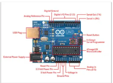
5 simple to utilize setting, an Arduinoare also similar to other microcontroller as it is a circuit board with chips that can be customized to do the various numbers of errands, the information had been send from the computer system to the Arduino microcontroller lastly to the particular circuit or machine with numerous circuits so as to execute the particular order or instructions. The information can be read by Arduino from information devices, for example, sensors, radio wire, trimmer (potentiometer) and can likewise send information to yield devices, for example, LED, LCD Screen, Speakers, and a DC metal gear motor. Figure 2.1 shows label Arduino Board.
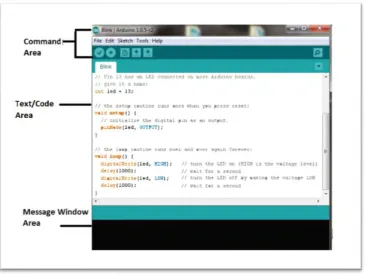
6 Figure 2. 2 Labelled IDE
.
7
2.2.2 Vision Sensor
This mobile robot requires a vision sensor as a major component in this project. According to Vans et al., (2014) an algorithm for a self-sufficient way following of a versatile robot to track straight and bended ways followed in the environment. The calculation utilizes a fuzzy rationale based methodology for way following with the goal that the mobile robot can copied the way of human driving. The technique joins a fuzzy directing controller, which guiding angle of the mobile robot for way following can be controlled, plus the fuzzy velocity controller which controls the forward straight speed of the portable robot for safe way following. The inputs to the fuzzy framework are given by the vision arrangement of the mobile robot. To catch pictures of the way forward of the portable robot and the vision framework decides the horizontal counterbalance, heading mistake and curvature of the way a camera is utilized. Vision System for image data is acquired using a low cost USB camera (webcam) mounted on the mobile robot. A notebook computer running MATLAB is connected to the CMOS camera.
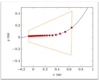
[image:20.595.226.411.593.719.2]Utilizing the extraneous parameters that had been found, the pictures of path taken was anticipated from picture coordinates of the pixel to the ground plane. The projection on ground plane yet later changed over to meters as it in millimeters at first. A specimen picture of the way taken amid tests is appeared in the Figure 2.2. The pixel coordinates of the midpoint of the way was extricated from the picture and these coordinates were anticipated onto the ground plane as appeared in Figure 2.3.
8 Figure 2. 4 Projection of the focuses owning to the way onto ground plane.
As a conclusion, firstly the mobile robot can effectively track a straight way, which demonstrates the viability of the fuzzy directing controller. Furthermore, the upsides of the fuzzy velocity controller are appeared by following a path with curved section.
9 the following postponement is smothered to around 10% of the picture width in the examinations with the best tuned parameters.
According to Gang Peng et al. (2012) route and movement control are key methods in the savvy mobile robot framework. Vision information is the most critical approach to see the environment, the vision-based, insightful control methods worried on Pioneer II mobile robot framework are introduced. The article seeks, picture division based on HSV (Hue-Saturation-Value) shading mode, grouping calculation and area based on CCD vision sensor.
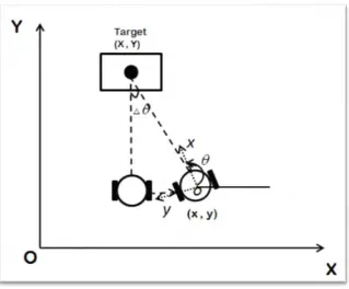
Based on Muneeb Shaikh et al. (2011) a vision tracking system for mobile robot by utilizing Unscented Kalman Filter (UKF). The proposed framework precisely gauges the position and introduction of the mobile robot by incorporating information got from encoders, inertial sensors, and active beacons. These positions and introduction assessments are utilized to pivot the camera towards the objective amid robot movement. The UKF, used as an efficient sensor fusion algorithm, is a progressed sifting strategy which lessens the position and orientation errors of the sensors. The outlined framework makes up for the slip mistake by exchanging between two diverse UKF models, which are intended to slip and no-slip cases, individually. The slip indicator is utilized to identify the slip condition by looking at the information from the accelerometer and encoder to select the either UKF model as the output of the system.
10 Figure 2. 5 The system depicting robot’s motion and orientation on the Cartesian
coordinate.
Composed system can find robot position by essentially lessening position blunders of the sensors, and consistently follow the objective with a superb vision following achievement rate under all the condition and situations.
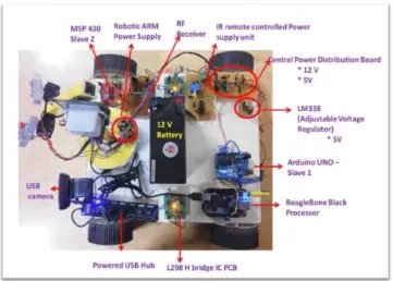
According to Sriram Emarose et al. (2015) the robot utilizes a webcam to confine and track the object of interest and a SONAR is utilized as a part of conjunction with the camera to gauge separation between the robot and the item. A 3 DOF automated arm is mounted on the robot to control the articles inside its workspace. The robot is fitted for working in various lighting conditions. A visual feedback circle is set up between the article and the robot for constant tracking. Path arranging of the robot is done based on the mean of the item area from 5 casings to acquire smooth move.
11 responsible for monitoring the illumination in the robot`s surroundings using the OPT 101 photodiode and triggers the onboard lighting of the robot The Arduino UNO microcontroller receives control commands from the BBB and which in turn drives the DC motors of the robot and the servo motors of the robotic arm. The limit switch in the gripper of the robotic arm sends a feedback to the BBB when the object is picked up. Figure 2.5 shows the robot development.
Figure 2. 6 Monocular Vision Based Autonomous Indoor Mobile Service Robot development